Electrical design
In this page, I will describe how I worked the electrical part for my final project.
Input device
Concept
As the input device, I used HC-SR04 to detect obstacles in front of the mobile robot. Because the robot will be able to go straight toward four directions (forward, backward, left, and right), four HC-SR04 will be equipped on the robot. Then, as I described in the assignment on week11, I created four electrical boards for each HC-SR04.
Designing board
The detailed process is described in the assignment week11.
Output device
Concept
For an output device, I used DC motors to rotate omnidirectional-wheels. The robot will be somehow big and carry something, so motor torque should be high. Then, I chose Tamiya geard DC motor for the actuator of my robot.
Designing board
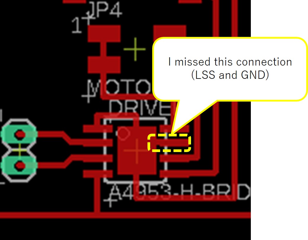
By referring to a past student’s page, I designed a PCB board to control 4 DC motors. As the motor driver, A4953 was used and each motor driver is connected by parallel connection. As the concept figure shows, 5V power supply for motor drivers is shared with Satshakit and power for DC motors is supplied separately.
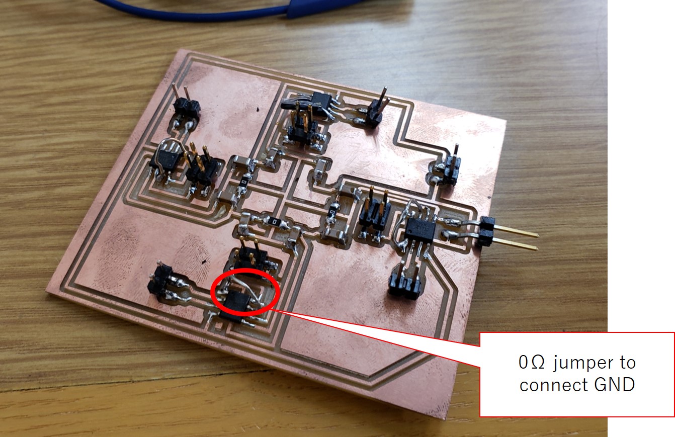
After completing milling, I realized that I forgot to connect LSS and GND for each motor driver (shown schematic and board images are correct ones). Milling again was a waste of time, so I used 0Ω jumper wires to connect LSS and GND.
Power supply connection
Concept
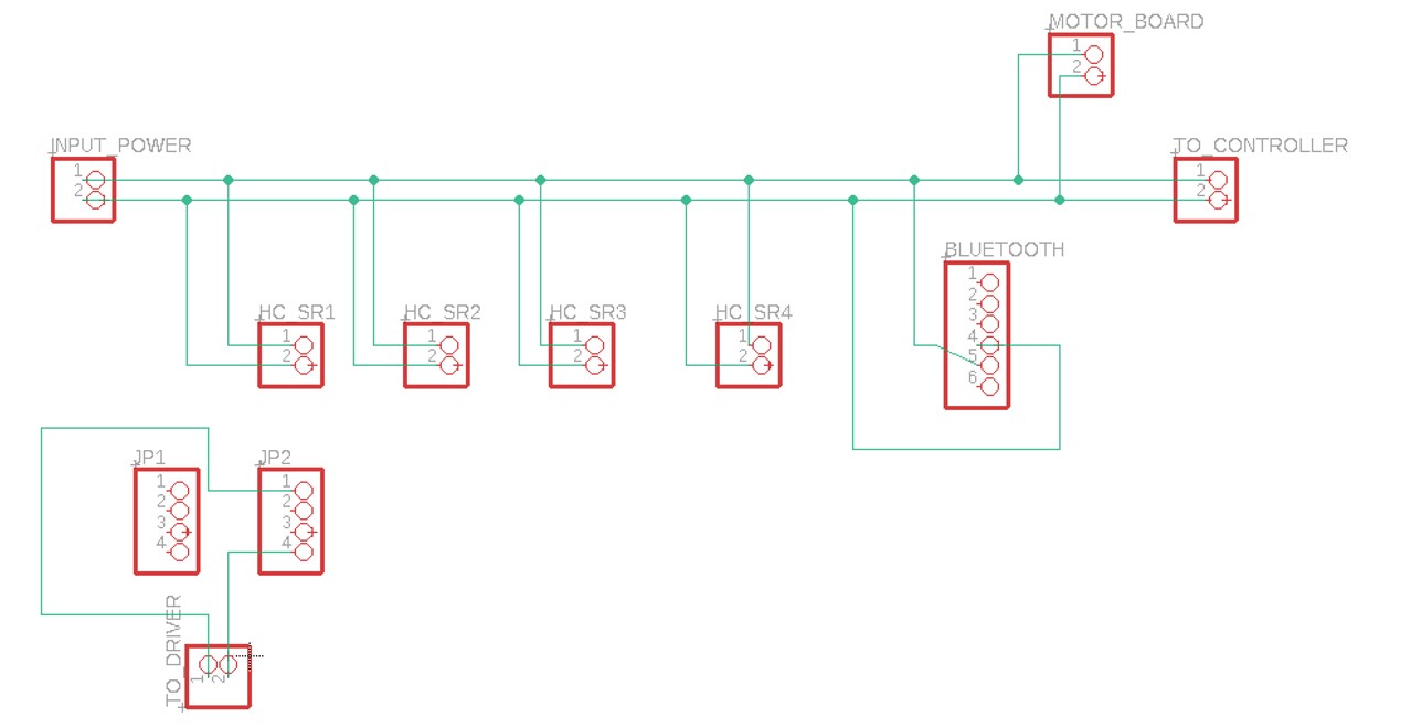
As the above description shows, there will be many PCB boards requiring 5V power supply. Preparing 5V power for each board independently is meaningless, so I planned to one power supply for the boards to share the power like the below figure.
Designing board
Based on the concept shown in the above figure, I designed an easy circuit to connect each board by parallel connection.
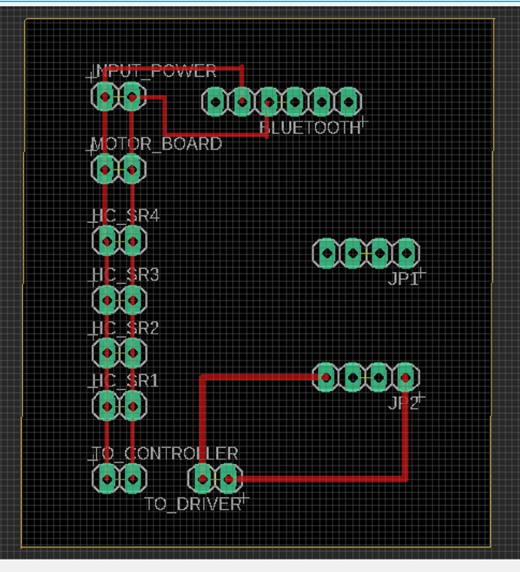
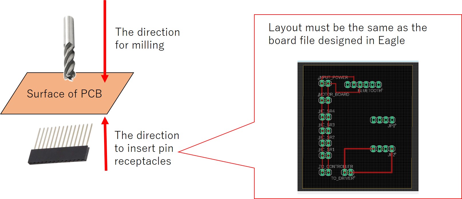
The process to create the board was a little different from other boards I had designed before. The board to share the power supply has a lot of pin receptacles, so to solder them on the board, I had to make holes to insert the pin receptacles into the board. The processes to make holes are described here. To create holes, I also had to export image files that showed only PADS. To mill the PADS, 1/32 dill was used.
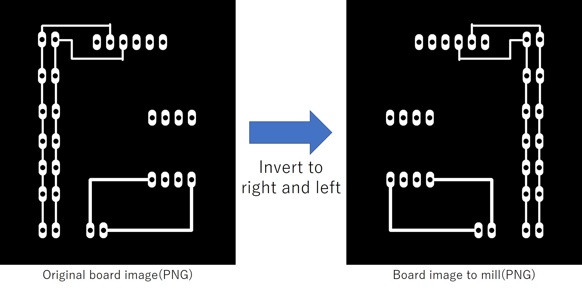
When pin receptacles will be soldered, the surface to solder and the one to mill must be the same, so the below figure shows, the directions to insert pin receptacles and milling are different from each other. In that case, the PNG file should be inverted to right and left. The inverted image files should be used for milling processes.
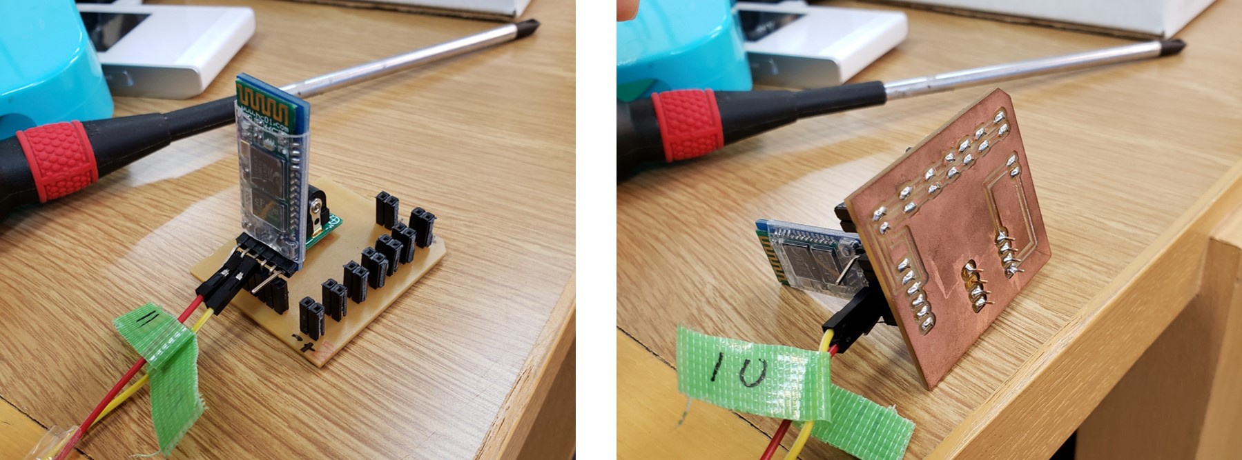
The photo of completed product is shown below.
Download link
Eagle files of Input devices can be downloaded from here.
Output device
Schematic file
Board file
Power supply
Schematic file
Board file