Mechanical design
In this page, mechanical works for the final project is described.
3D design
First of all, before designing the robot, I referred some existed mobile robots that are used for research applications.
Turtle Bot2
HCR-A
One of the points in common between these robots is that there are some plates so that sensors or other devices can be retrofitted on the robot. Then, I sketched a draft design like the below picture.
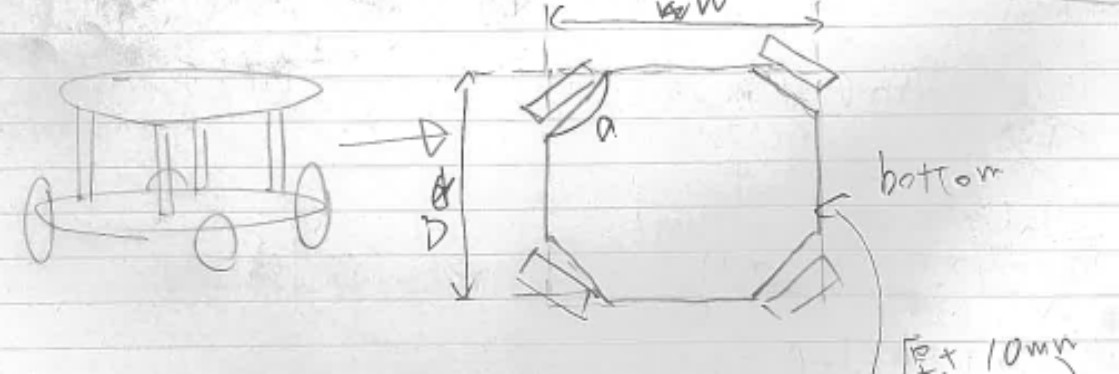
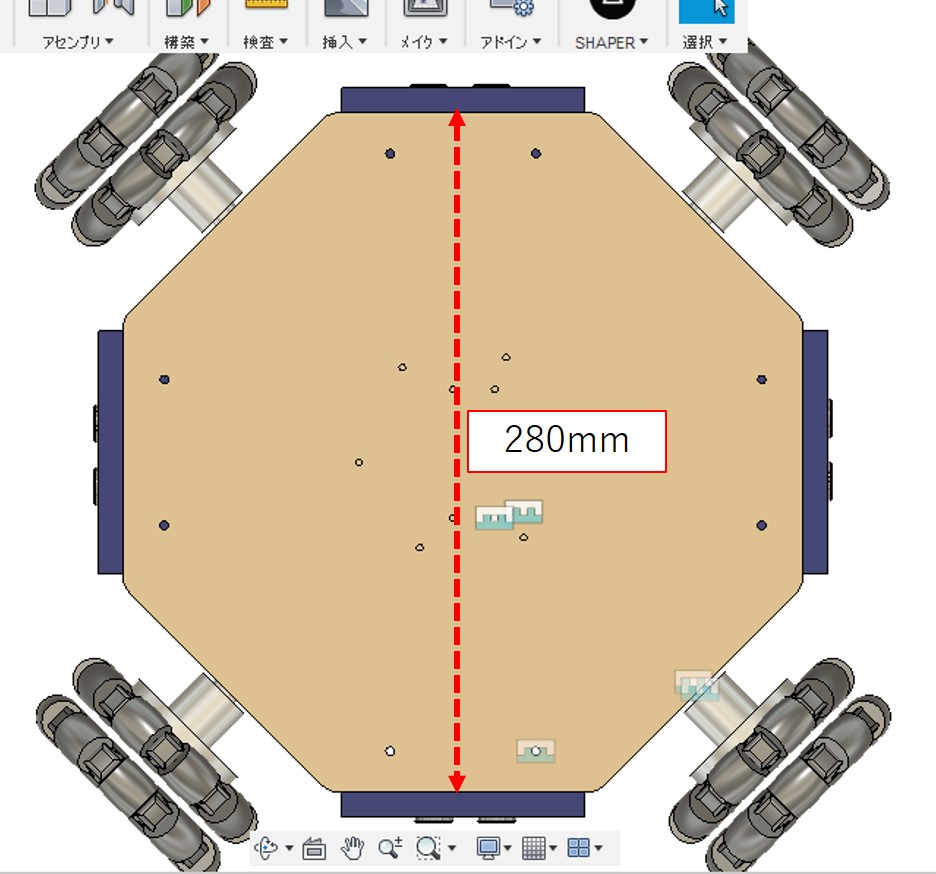
1. Base plates
The shape of the base plates is a simple regular octagon so that four omnidirectional wheels and four HC-SR04 can be equipped. I defined the size of the plates as approximate as the performance limit of the laser cutter in Fablab Kannai. The max size that the laser cutter can deal with is 300mm X 450mm, so I drew the regular octagon from a square 280mm on a side.
2. Components
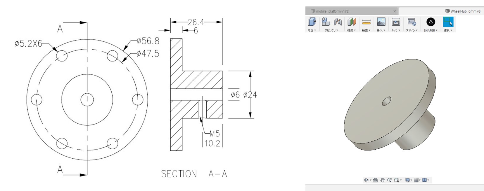
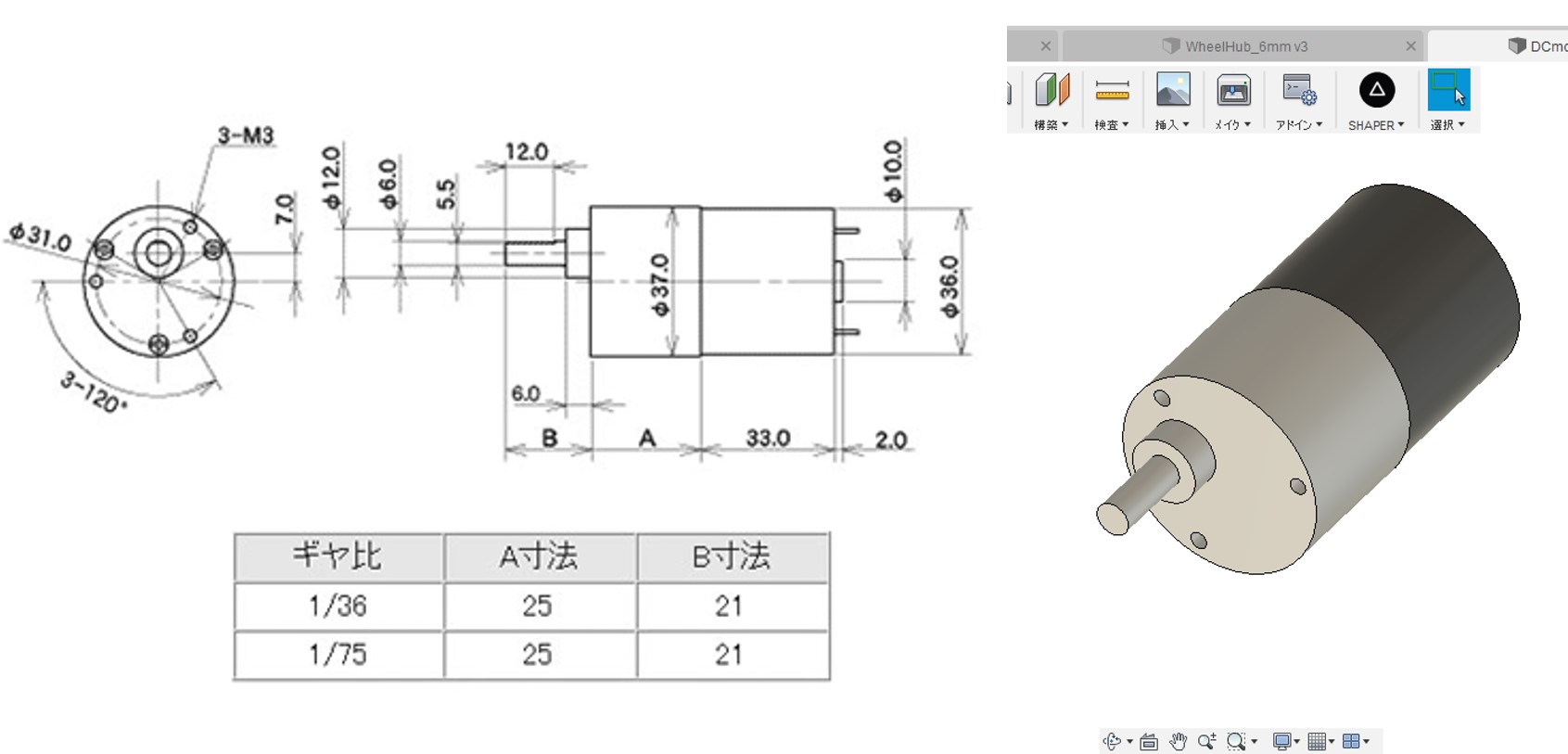
To define appropriate sizes of each part of the robot, I created easy 3D models of some components, DC motor and wheel hub.
Based on the drawings of these components, I created their 3D models.
3D models of other components, omnidirectional wheel and HC-SR04 were downloaded from GrabCAD.Omnidirectional wheel model and HC-SR04
3. Attachements for components
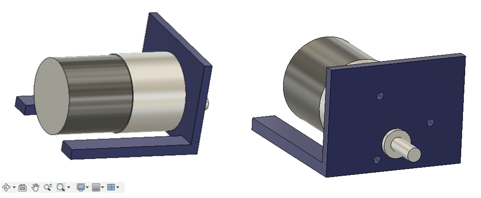
Based on the above 3D models of components, attachments for motors and HC-SR04 were made.
The process to create it for HC-SR04 is described week3.
The attachment for DC motors was shown the below picture.
As a result of the above designs, 3D model of the mobile robot was made like the below figure.
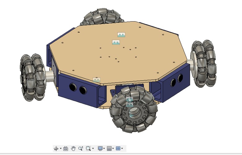
Note:Although my completed robot has three base plates, this 3D model has only two ones. This is because I realized there should have been one more base plate to put PCB boards. Moreover, creating another base plate did not need 3D model, just copying and projecting existed model was enough, so this 3D model does not show the middle base plate.
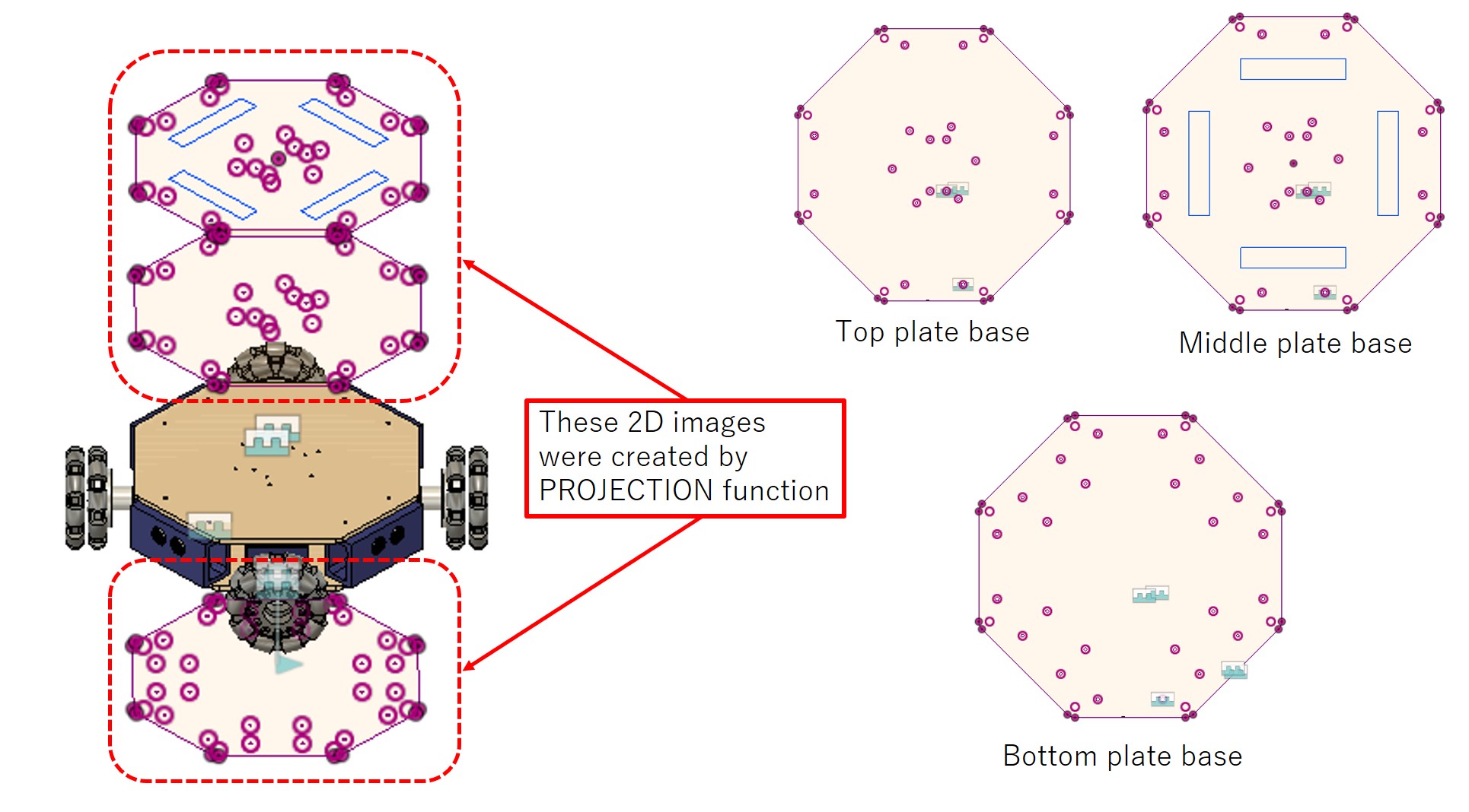
2D design
To create 2D design to cut out, I used PROJECTION function in Fusion360. To import to the laser cutter machine, I exported these models as DXF files.
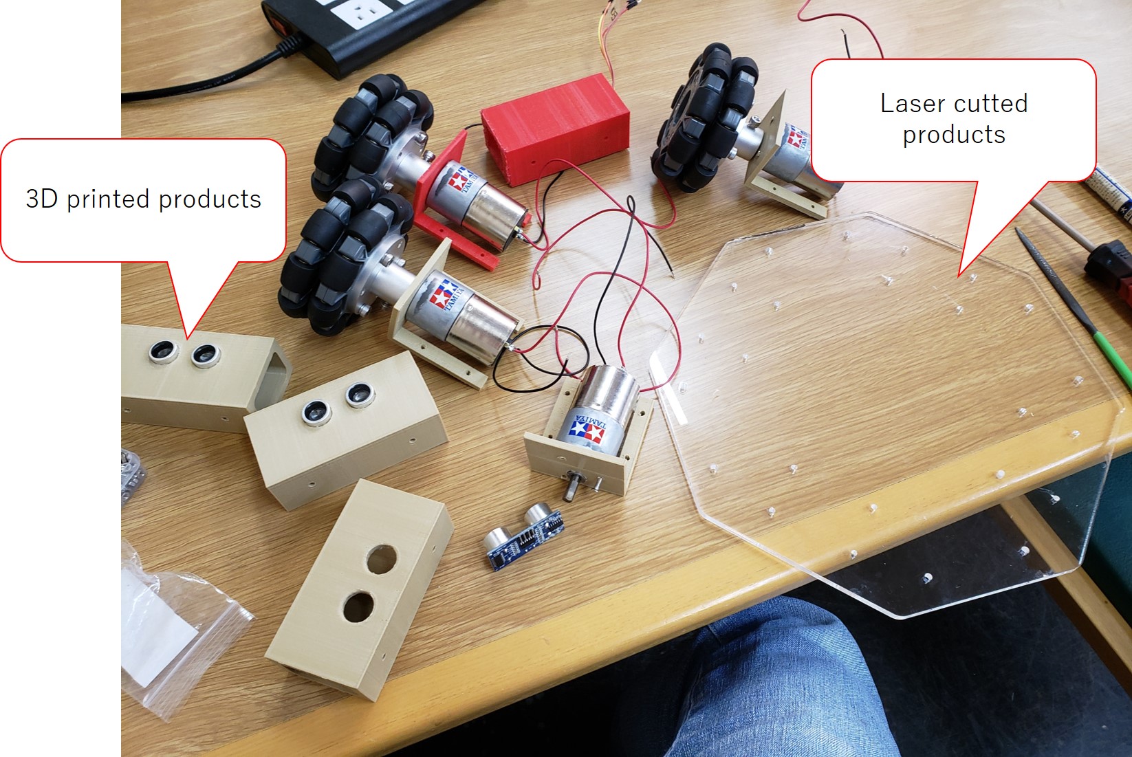
Assembling components
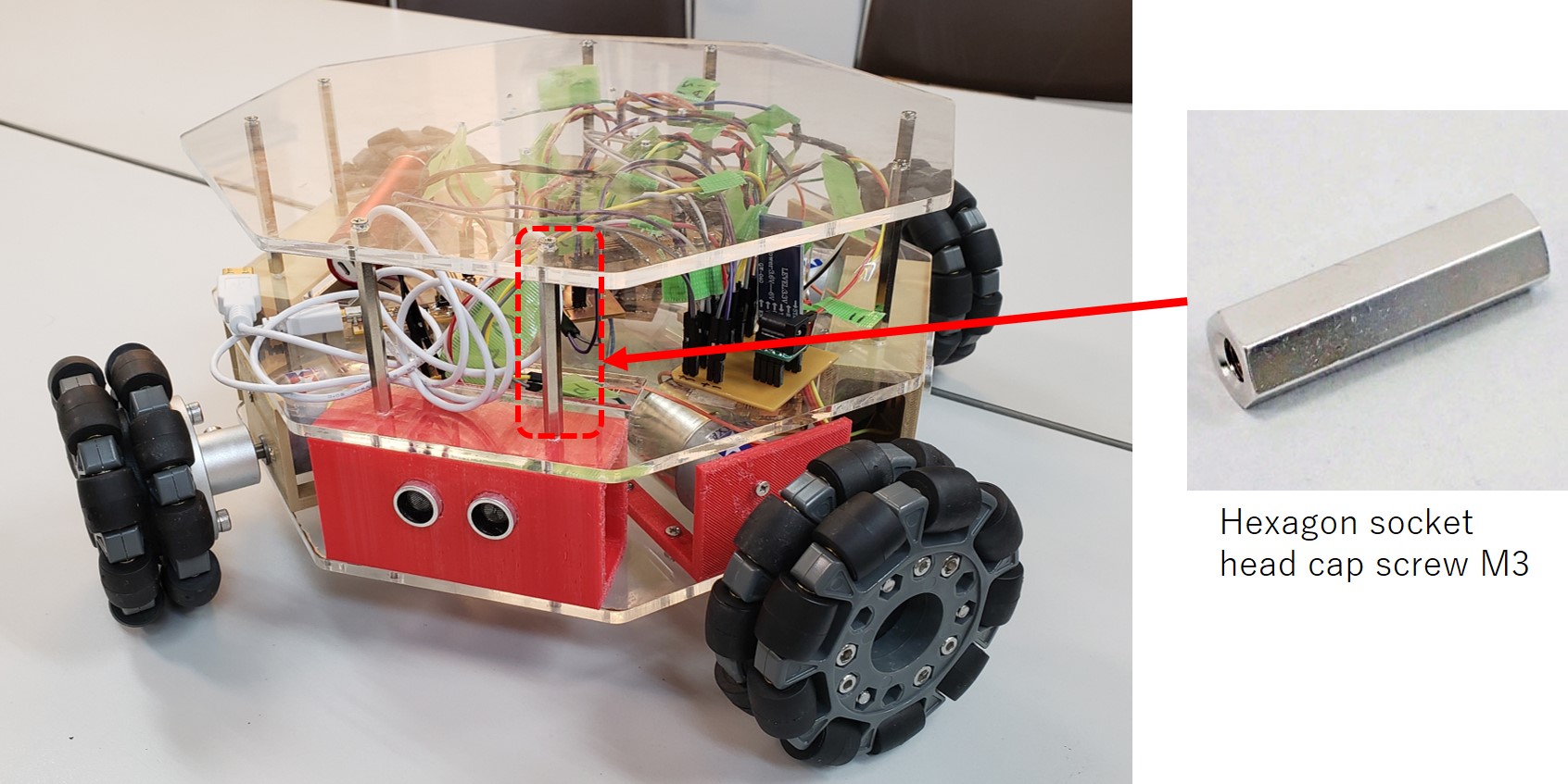
After completing 3d printing and laser cutting, these components were assembled by M3 screws.
The below picture shows assembled robot including PCB boards. Top, middle, and bottom base plates are connected by M3 screws and hexagon socket head cap screws M3.
Download link
2D design
Top base plate
Middle base plate
*Bottom base plate
3D design
Whole robot body
Note: The file size of my 3D model is more than 10MB, so I could not upload it on my git and skecthfab.