9. Embedded programming
Assignment
individual assignment:
read a microcontroller data sheet
program your board to do something,
with as many different programming languages
and programming environments as possible
group assignment:
compare the performance and development workflows
for other architectures
Learning outcomes
Identify relevant information in a microcontroller data sheet.
Implement programming protocols
Have you?
Documented what you learned from reading a microcontroller datasheet.
What questions do you have? What would you like to learn more about?
Programmed your board
Described the programming process/es you used
Included your code
What we have done
FabAcademy2019-FabLab Kannai lab site
What I have done
Read ATTiny 44 datasheet
This week’s first assignment was to read a microcontroller data sheet. I choose ATTiny44 for my board, so I read about it.
- ATTiny 44 is working in 8bits
- Rewritable for 10000 times
- There are two PWM Channels, Each
- Operating Voltage:1.8 – 5.5V. This means I can use this with at least 2 AAA battery.
- PIN assignment
Here’s pin assignment. This is very useful because pin number is defferent beween microcontroller and Arduino.
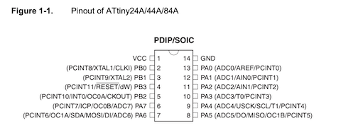
There was the explanation about how each pins work. Before I read it I knew only about which pin was used for PWM, etc from the image above.
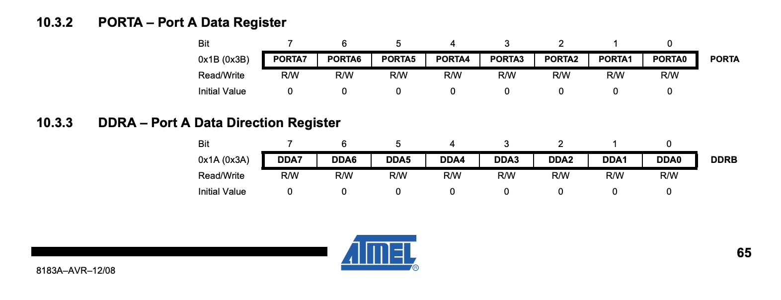
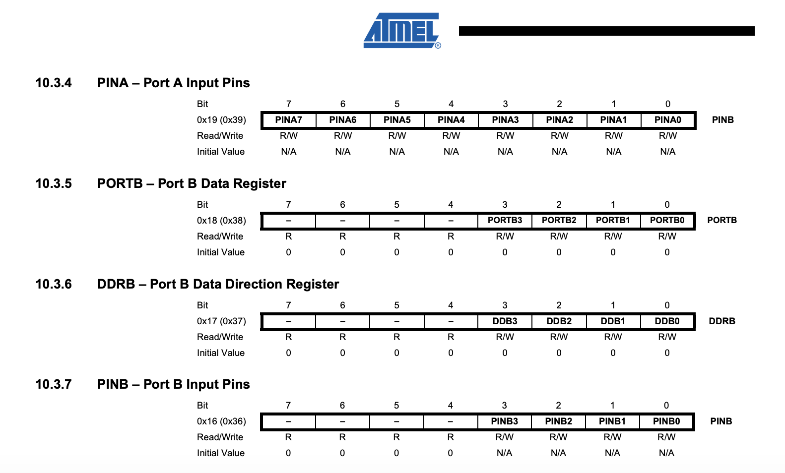
In this, there were explanation about more low-level mechanizm.
Each port pin consists of three register bits: DDxn, PORTxn, and PINxn.
DDxn control the directions: 1 means output, 0 means input.
PORTxn manages pull-up activation: 1 means activated, 0 means not activated
PINxn turns PORTxn to opposite when it has 1. For example, when PORTxn has 1 and PINxn has 1, PORTxn turns to 0.
Here’s default value of each pins
Writing C code
This time I wrote C code intended to make LED on the board blink regularly.
I added this in hello.ftdi.44.echo.c.make
#define led_pin (1<<PA7)
#define led_port PORTA
#define led_direction DDRA

void blink(){
    set(led_port, led_pin);
    _delay_ms(100);
    clear(led_port, led_pin);
    _delay_ms(100);
}
blink();
Saved it as “hello.ftdi.44.echo.blink.c” and rewrote line 1 in make file as following.
PROJECT=hello.ftdi.44.echo.blink
And wrote it with FabISP.

I run the codes below on Terminal.
make -f hello.ftdi.44.echo.blink.c.make

sudo make -f hello.ftdi.44.echo.blink.c.make program-usbtiny-fuses

sudo make -f hello.ftdi.44.echo.blink.c.make program-usbtiny

Run term.py and type several charactors.
python term.py /dev/cu.usbserial-A105MN36 115200
However, LED on the board never blinked. From my experience, I suspected delay length was too short. So I changed it from 100ms to 1000ms and repeat the writing procedure above.
#define led_pin (1<<PA7)
#define led_port PORTA
#define led_direction DDRA

void blink(){
    set(led_port, led_pin);
    _delay_ms(1000);
    clear(led_port, led_pin);
    _delay_ms(1000);
}
Now it’s working. During I run term.py, when I type something on keyboard, LED on the board blinks.
Writing Arduino code
Then I wrote code with Arduino. This code intended to turn on LED when you push button on the board.
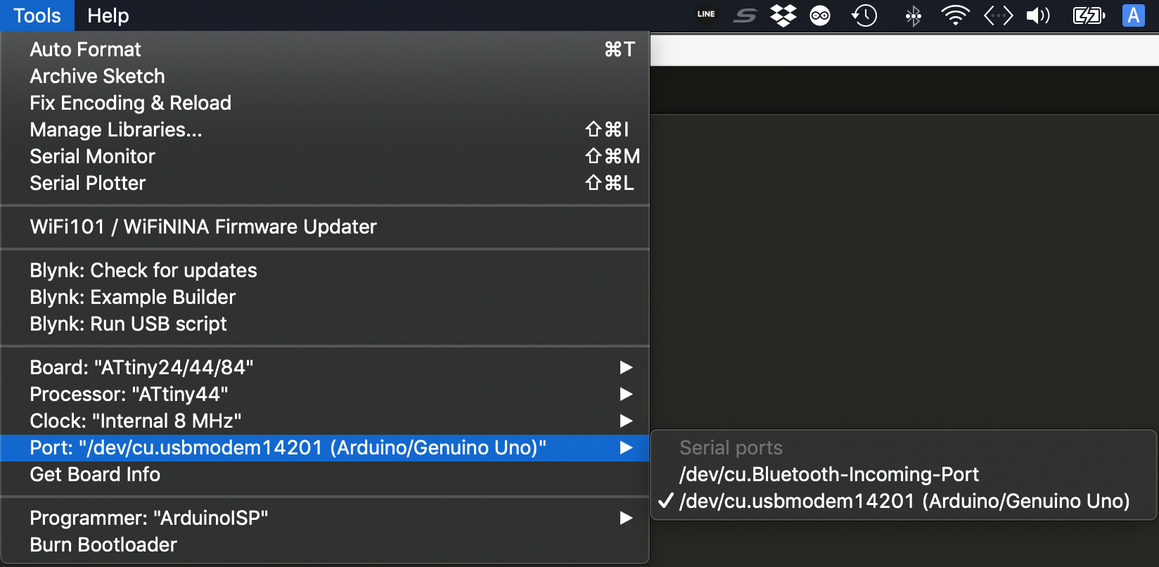
And I write it on the board through Arduino ISP
You can set it up from Tools > Programmer > Arduino ISP
Writing with Arduino
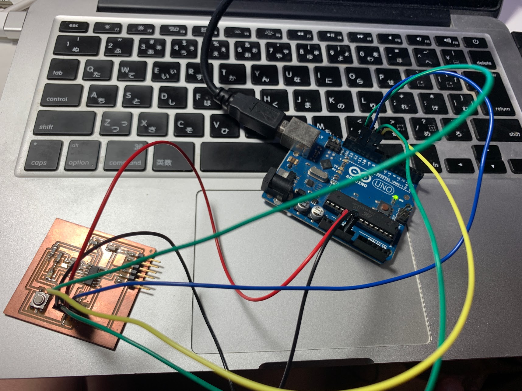
Arduino pins should be connected attiny pins as follows
| Arduino | ATtiny44 |
|---|---|
| GND | GND |
| 13 | SCK |
| 12 | MISO |
| 11 | MOSI |
| 10 | RST |
| 5V | VCC |
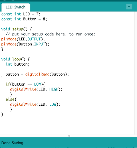
Here’s the code I wrote on Arduino.
const int LED = 7;
const int Button = 8;

void setup() {
  // put your setup code here, to run once:
pinMode(LED,OUTPUT);
pinMode(Button,INPUT);
}

void loop() {
  int button;

  button = digitalRead(Button);

  if(button == LOW){
    digitalWrite(LED, HIGH);
    }
  else{
    digitalWrite(LED, LOW);
    }
}
Files
Arduino file hello.ftdi.44.echo.blink.c hello.ftdi.44.echo.blink.c.make