This is the week four of fab lab.In this week we have to learn, how to make a PCB using the PCB milling machine.Here in Fablab we are using the Roland monoFab SRM-20 .
Assigned Task
Group Assignment:
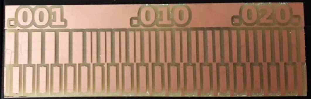
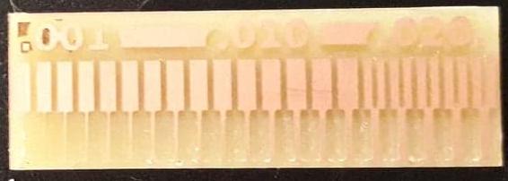
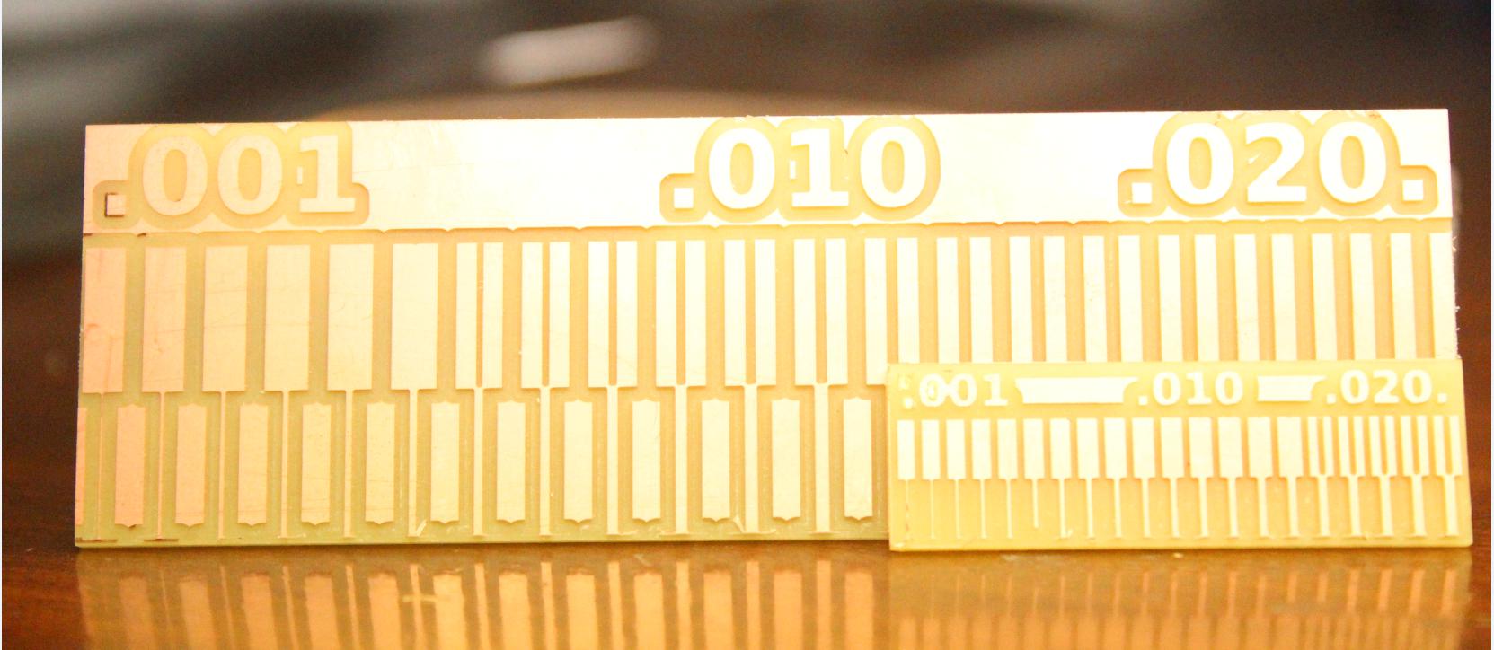
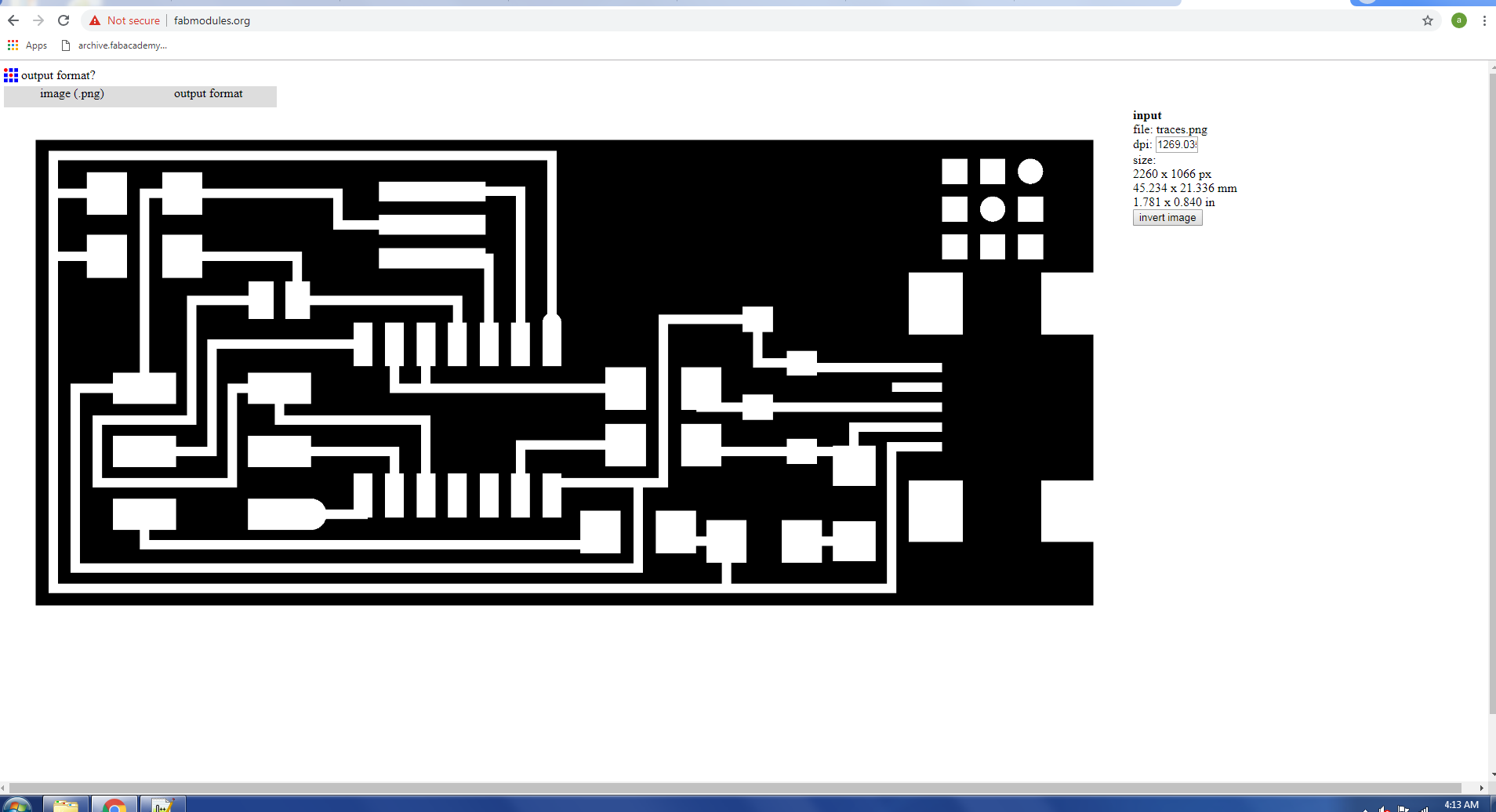
For the group assignment, we have to characterize the specifications of PCB production process using the PCB milling machine. For this we are using the FR-1 board for PCB, for the both group and individual assignments. In the process first we have to make traces with the 1/64 drill bit and also make outline using the 1/34 bit drill respectively. so we started our group assignment, first we download the given files of traces and outline and make it the rml files so we can go milling process. We are making the rml files by
using
this link fab modules.
And finally we made this PCB.
Here we did a mistake, we changed the dpi but the autal dpi was 5000 and did not notice the dimensions in Inches.
But after this mistake we did 2nd attempt and set the 2000 dpi.
From this task we come to know how thin the traces of milling the PCB can be made using 1/64 tool used for traces and 1/32 tool used for cutting outline.
Individual Assignment
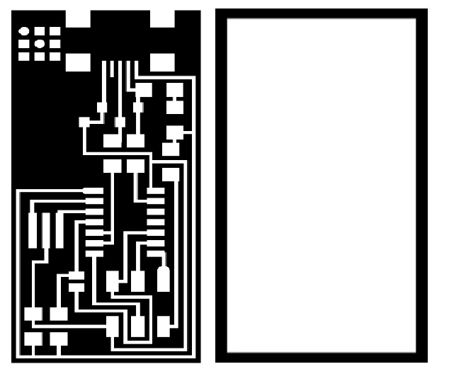
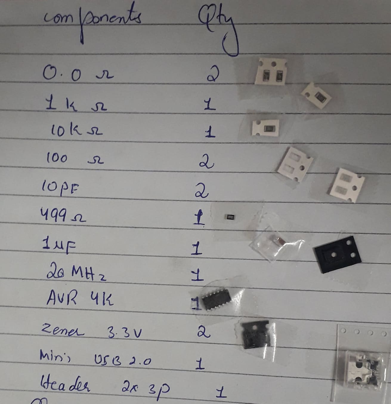
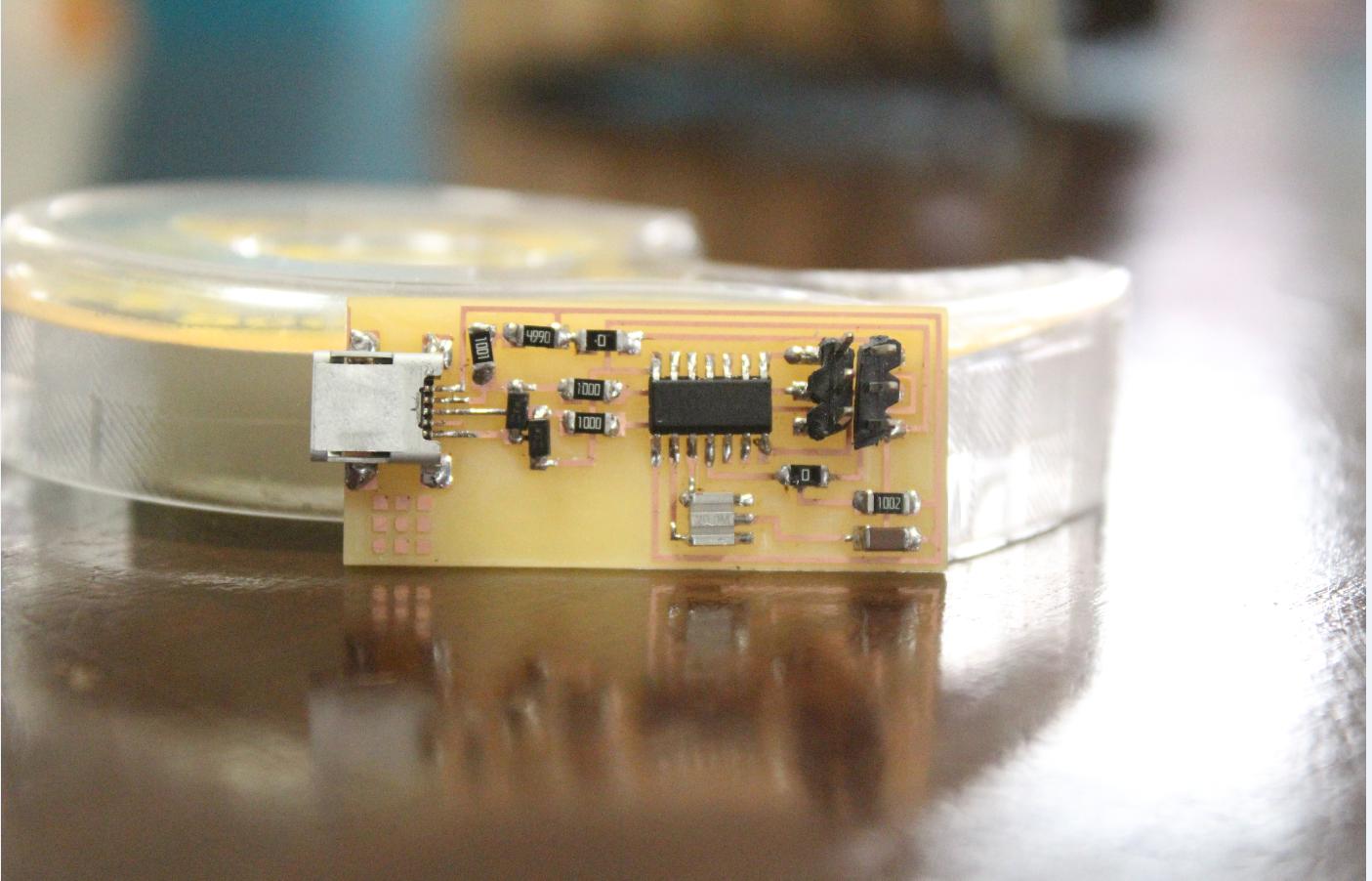
The task for this week is to make an in-circuit programmer by milling the PCB(making, soldering and uploading the program in board).
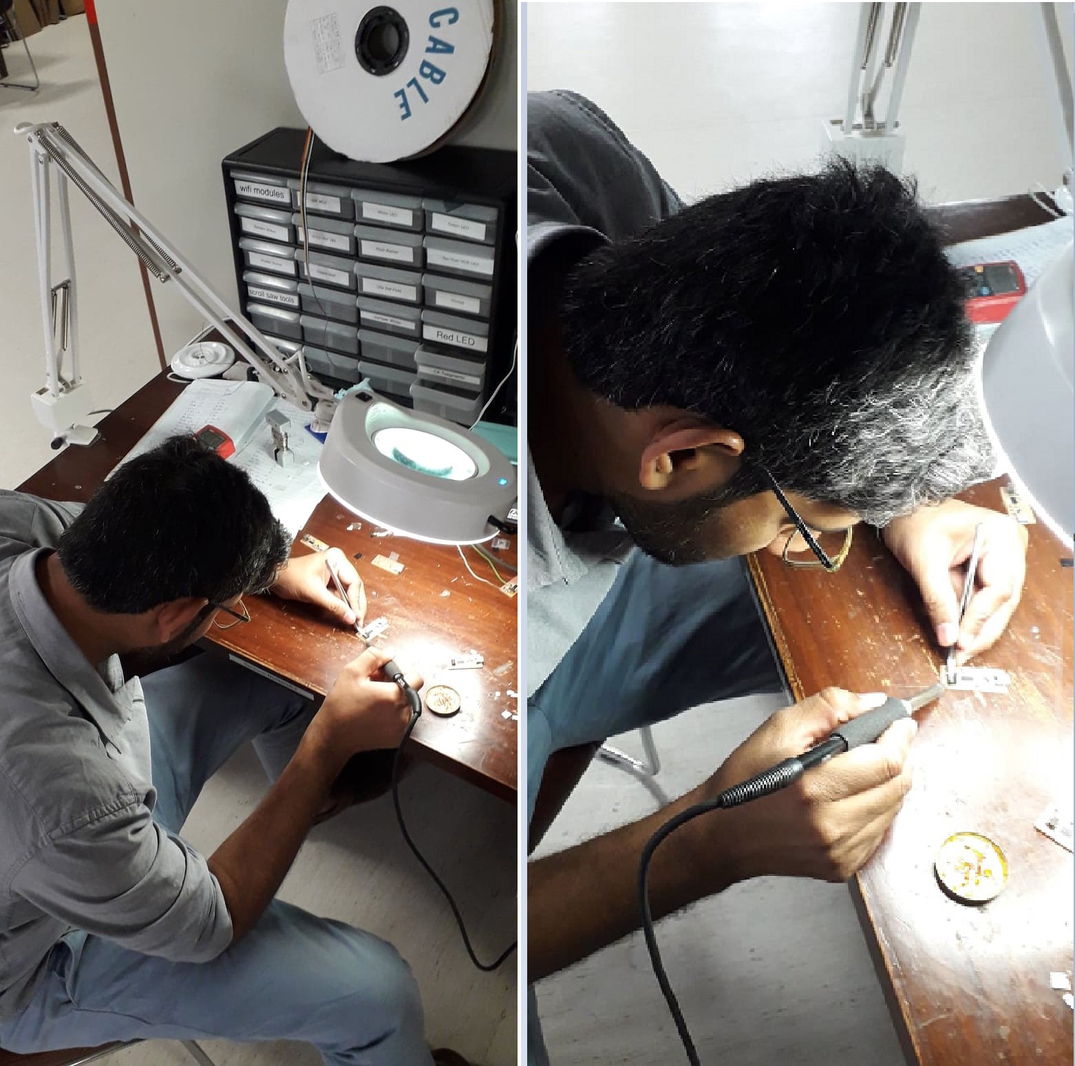
Being a Mechatronics Engineer, Electronics and electronics components are not new for me, and i have also knowledge about the throught hole components's soldering but its the first time to do the soldering of SMD based components.
I download development board file from our week 5 lecture.
Traces and Outline
Now I have to generate the rml files of these two files, so i can go to yhe next step.
Select the image that you have download from week 4.
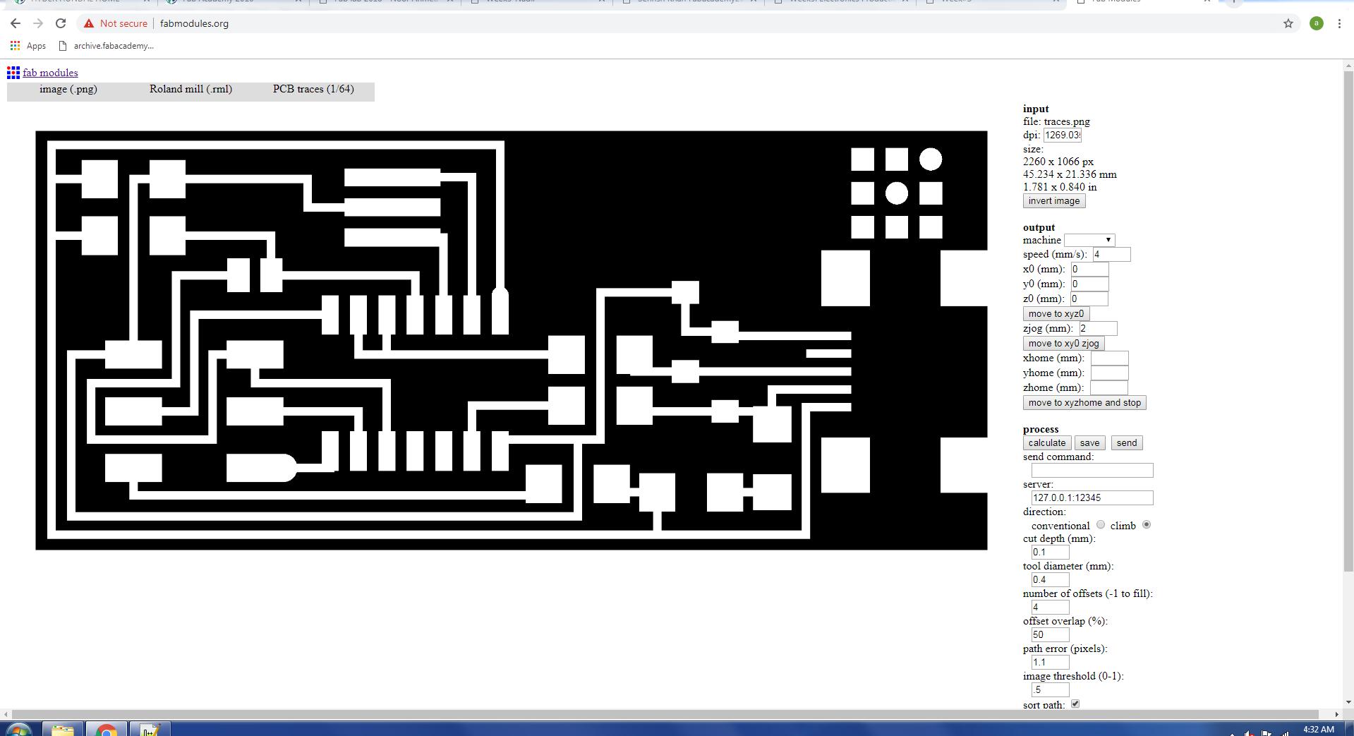
Select the milling machine, i did select the Roland mill.
Click on the process and select the drill bit, if you have to cut the traces select the 1/64 bit and if you want to cut the outlines select the 1/34 bit respectively.
Check the dpi, dimenions and x,y,z it must be 0,0,0.
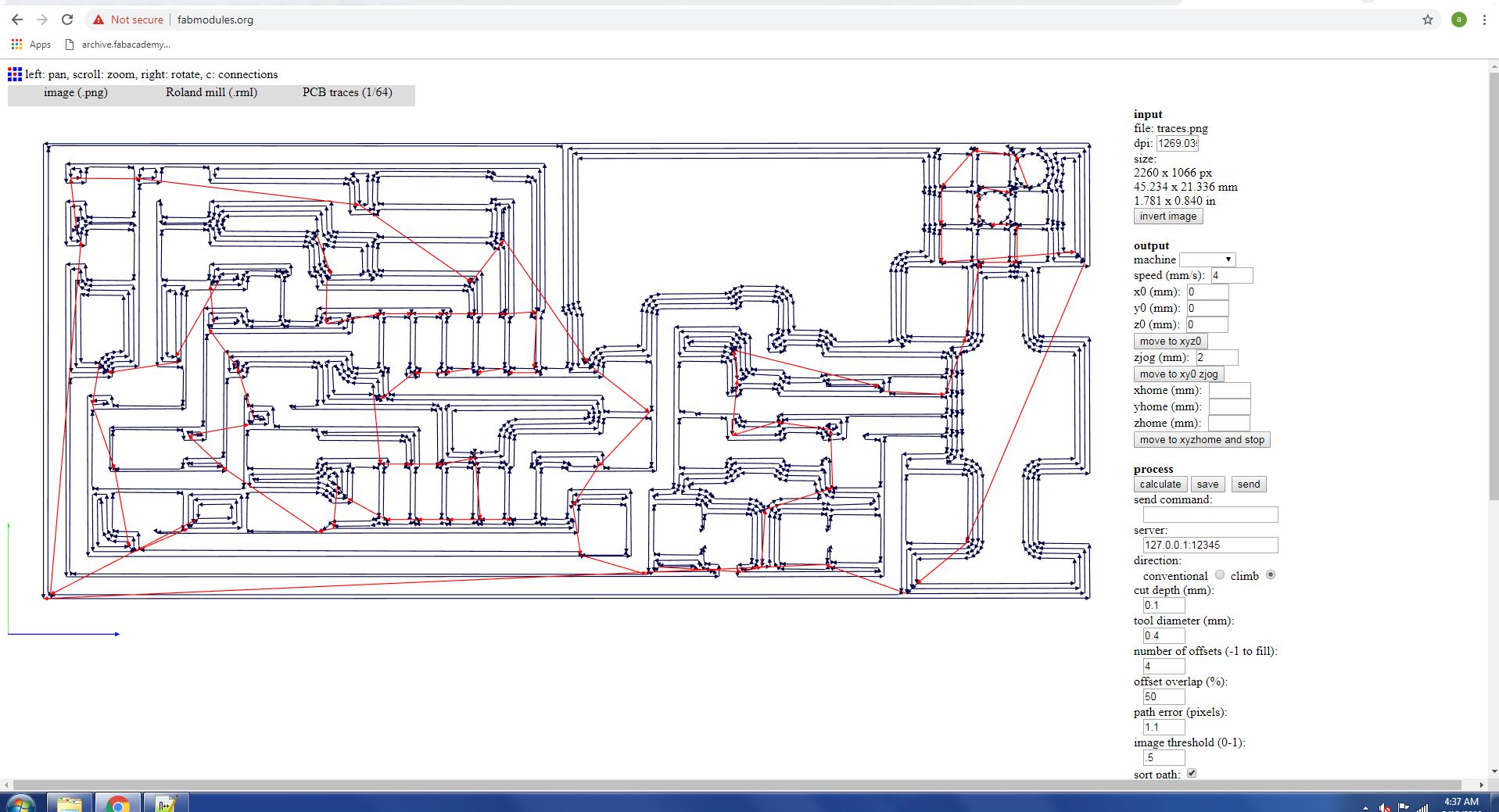
Click on the calulate.
Now rml is ready.
Now save this rml file and go for the milling machine.
Follow the all these steps and make the rml of outline.
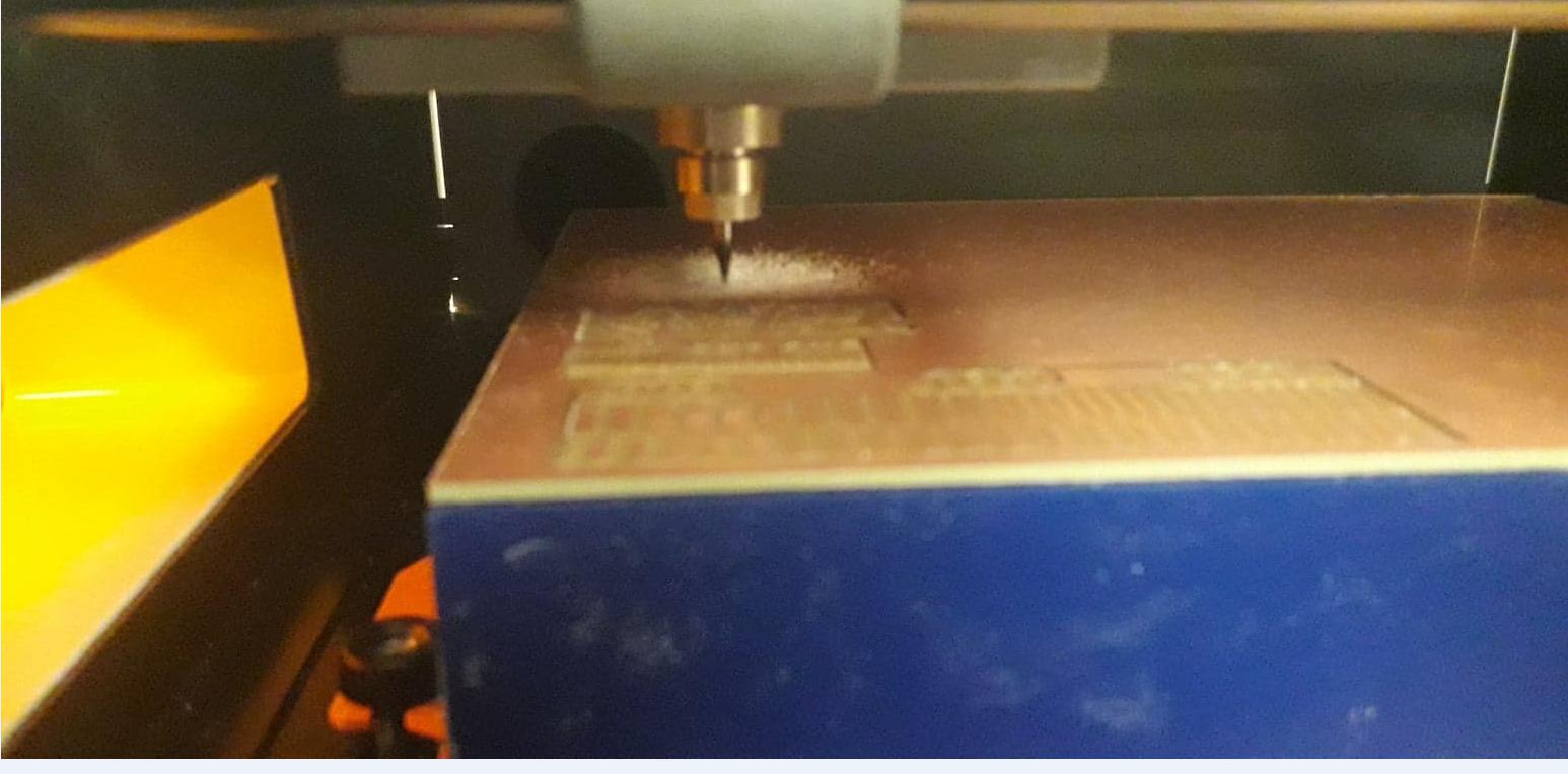
After generating RML we send both files to ROLAND monoFAB SM-20 Machine.
Steps of the maching process.
Place PCB on board.
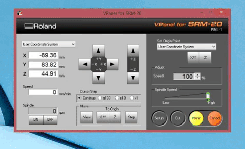
Open VPanel for SRM-20 in Desktop.
Change the drill bit.
Select origin to x/y and z axis by changing values of x, y and z axis from where it should be start.
Adjust drill bit until it touches PCB board.
Change Z-Axis value little bit to dig PCB board slightly, then set new value of Z-Axis as origin.
click on "Cut" and locate .rml file which we want to use.
>click on "Output" to start the process
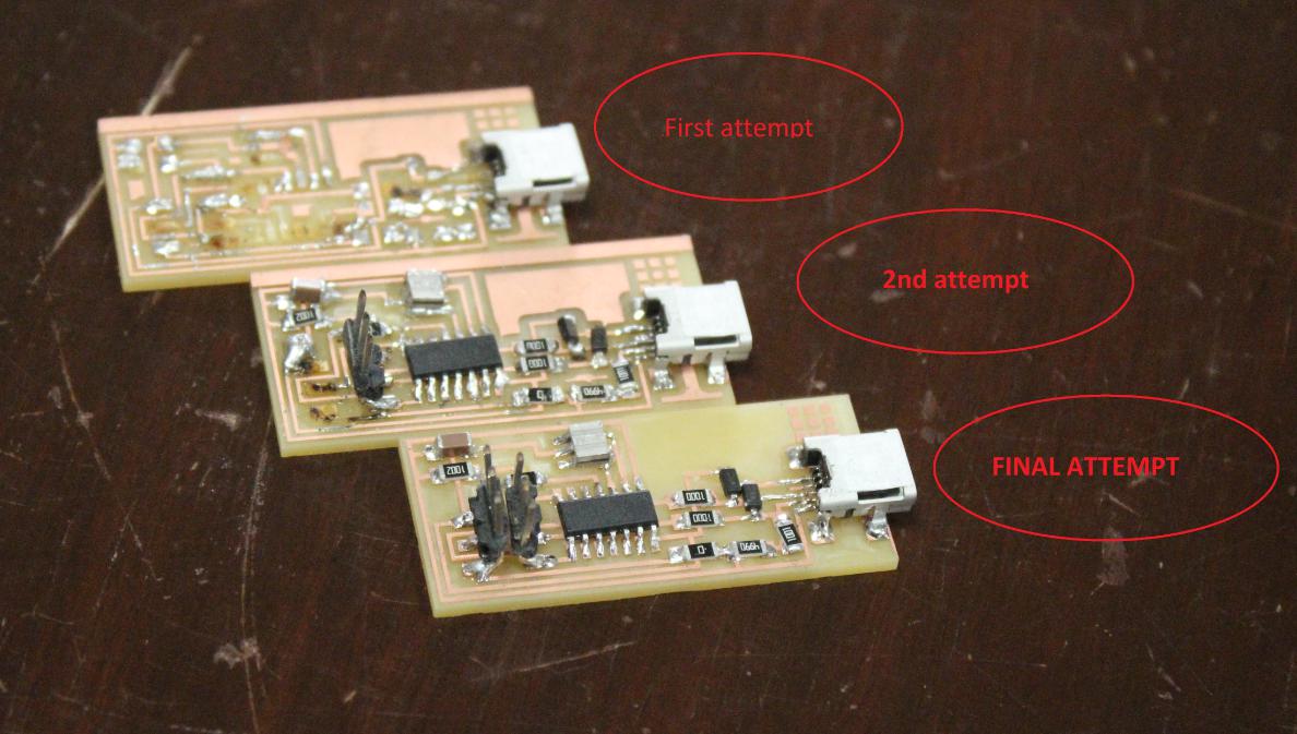
After the completion of this process my board is ready and i will go for the soldering.
Actually i am not good in soldering since my Bachlors degree time, I made some mistakes and make another board but there were also some problems during uploading the program so i made the third one board and that is the final board.
Programming ISP
Now it is the important part that is programming for programming our circuit. For this we dedicated one computer of our lab to LINUX and installed UBUNTU in that computer. By the way I never used LINUX before OS.
For programming ISP using Ubuntu a brief step-by-step process is explained HERE.
Now in order to burn program in my board through Linux, I Connected my ISP board with my Instructor's ISP board.(I forget to take a picture)
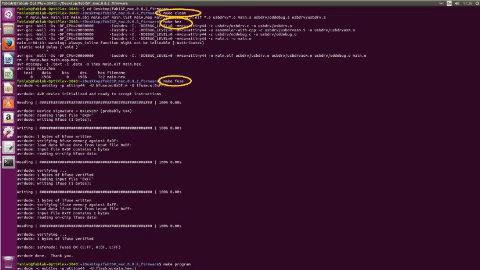
After competion the above steps I used the following commands.
make clean
make hex
make fuse
make program
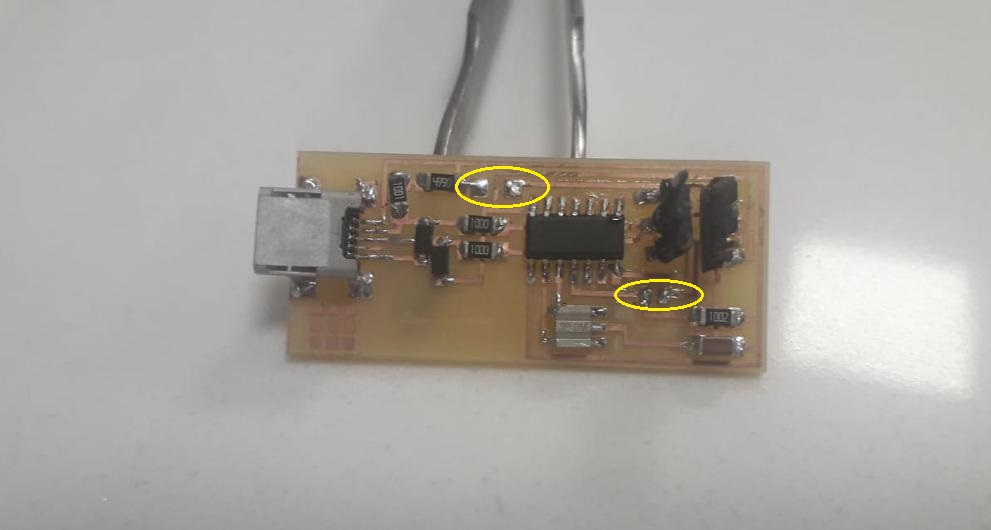
So here the programming is done, In the last step we have to remove the zero ohm resistor from circuit board.
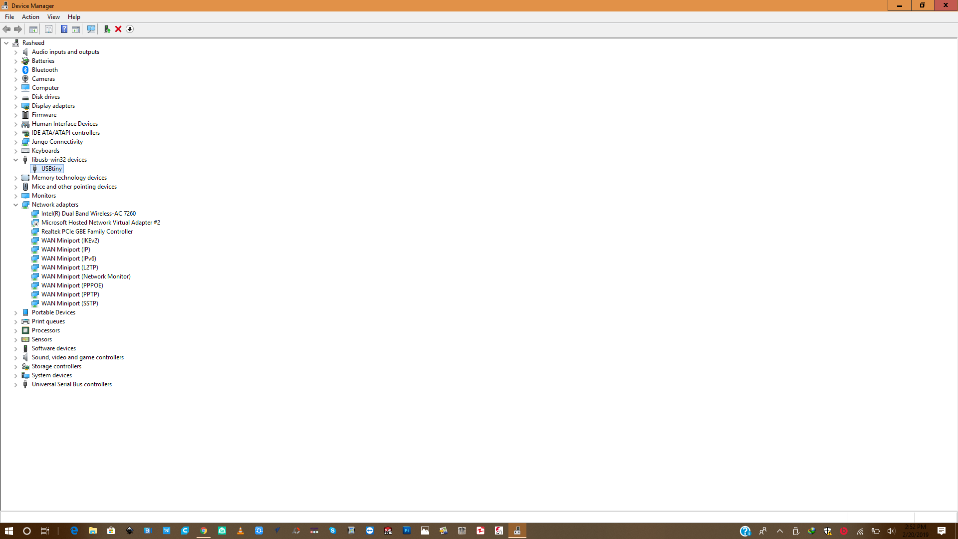
To operate it from a windows based PC we have to install the drivers for this programmer. Just download this
Adafruit Driver Installer Once the driver installation is done, you can plug in your device and check it in the "Device Manager".
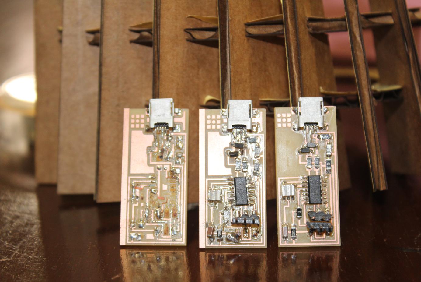
Removing Zero Ohm resistors
The last step to make your device an FAB ISP programmer is to simply remove the Zero ohm resistors, then your final circuit will look like this.