For the individual part prof. Neil told us to make something big, and When it comes to making something big, there were many different ideas in my mind. I started to search for a few design ideas, first
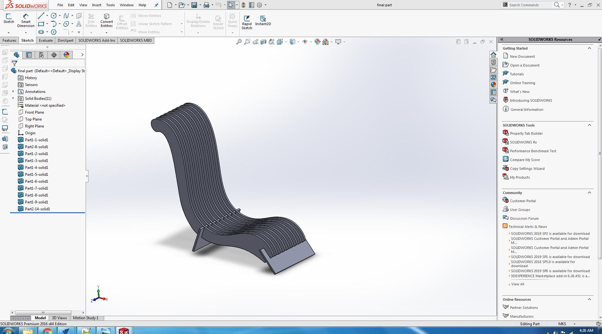
I decided to make a press fit table I started my work on solidworks but it was not satisfing me so I decided to move for the next Idea and I decided to make a relaxing press fit chair.
I did not continue this design and moved for the final design.
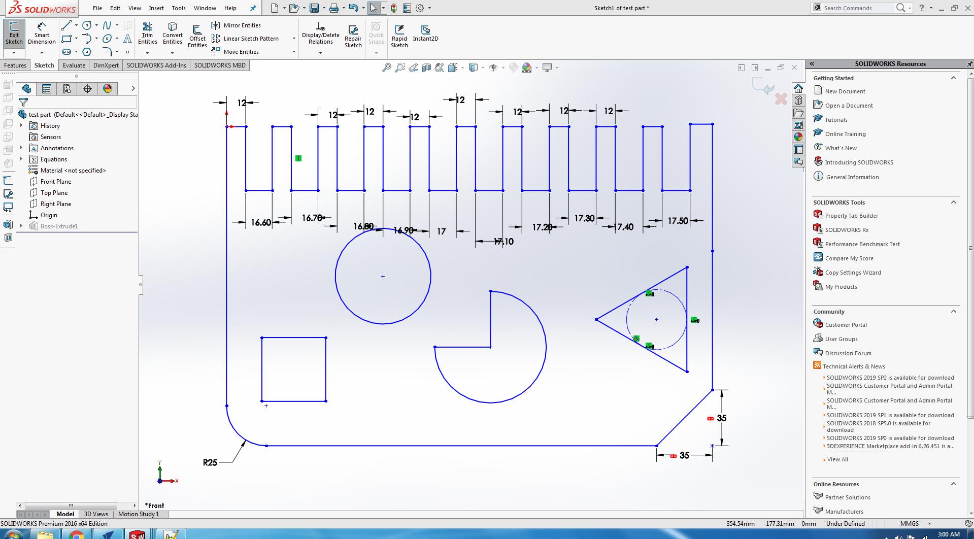
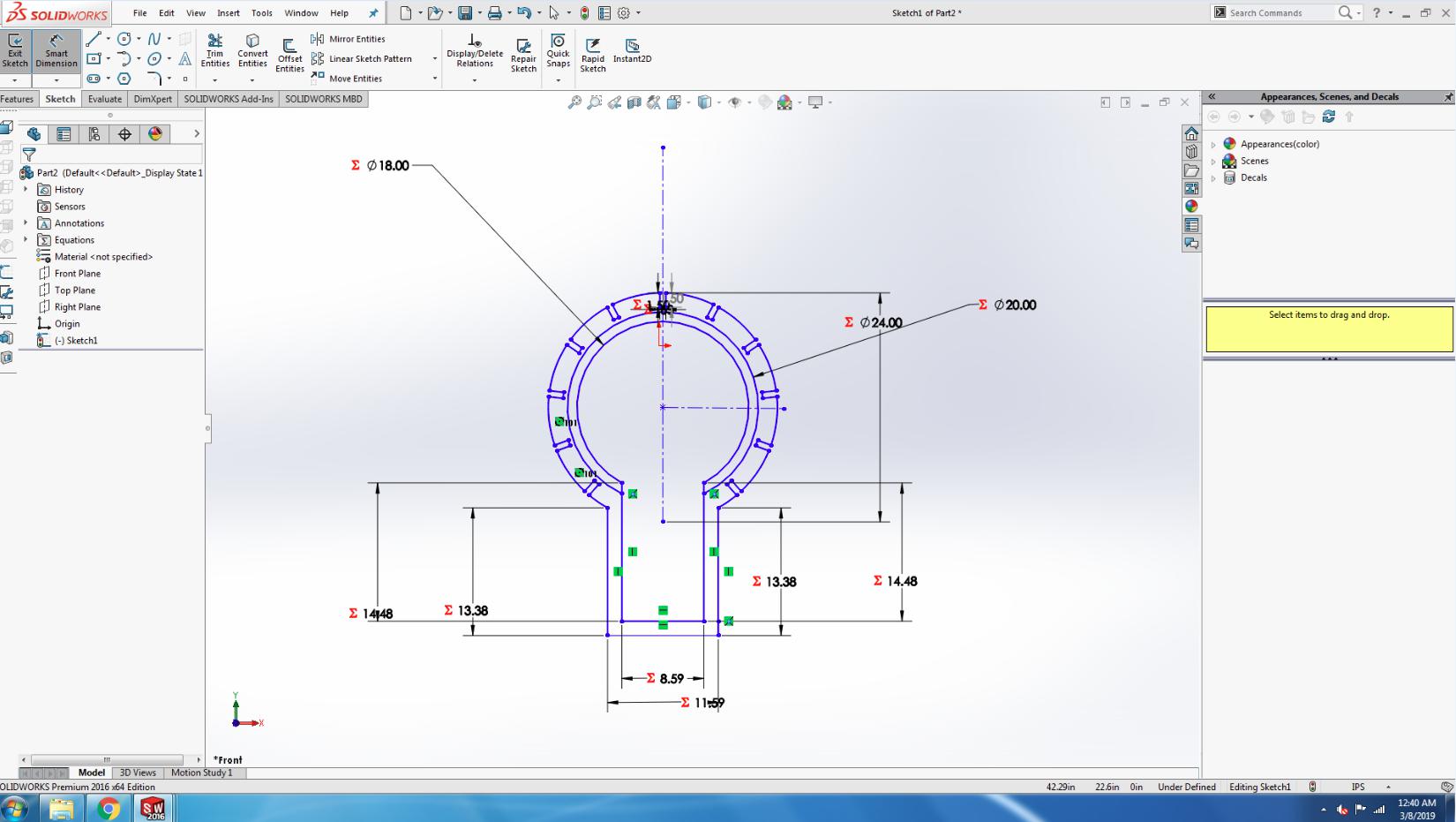
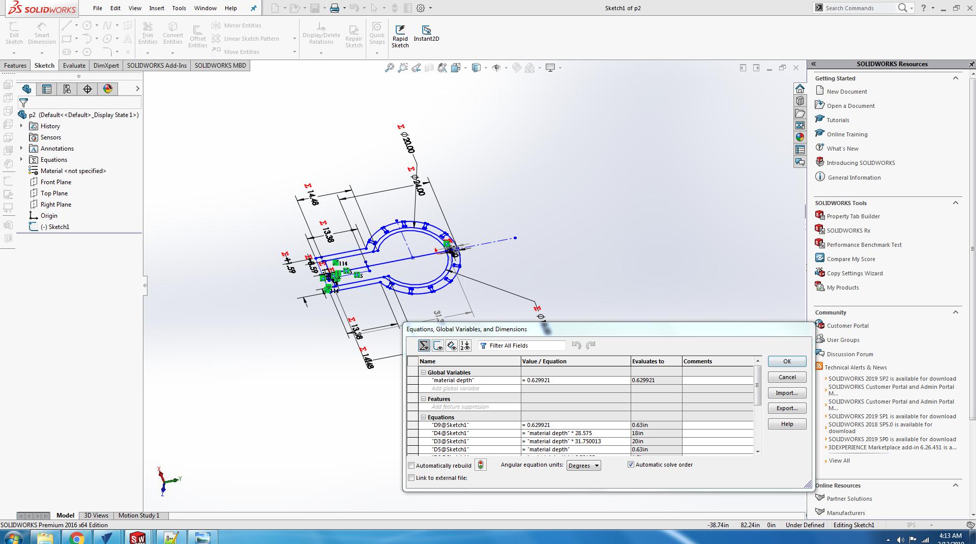
Open the Solidworks.
Make a new file part for design.
Set the units and plane.
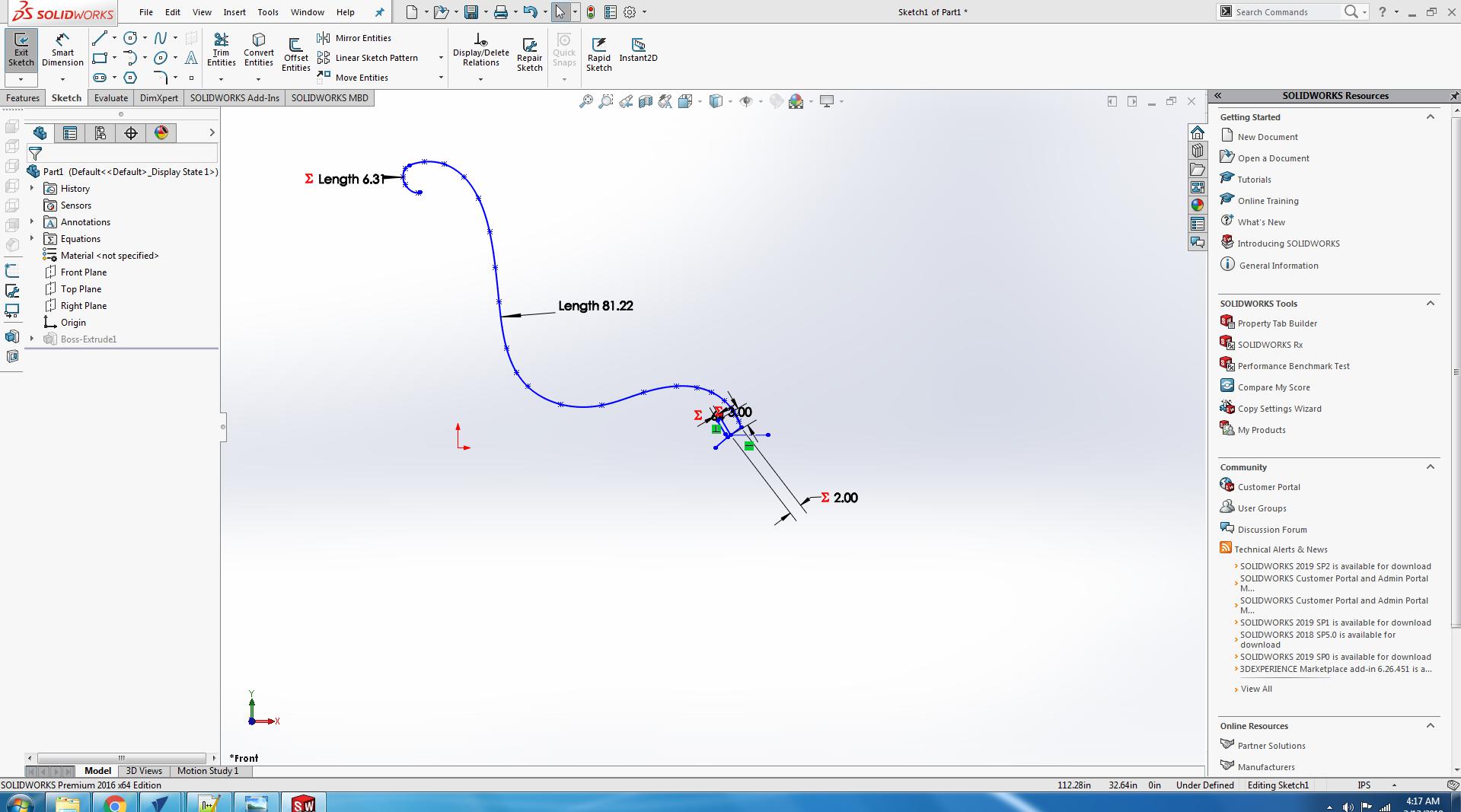
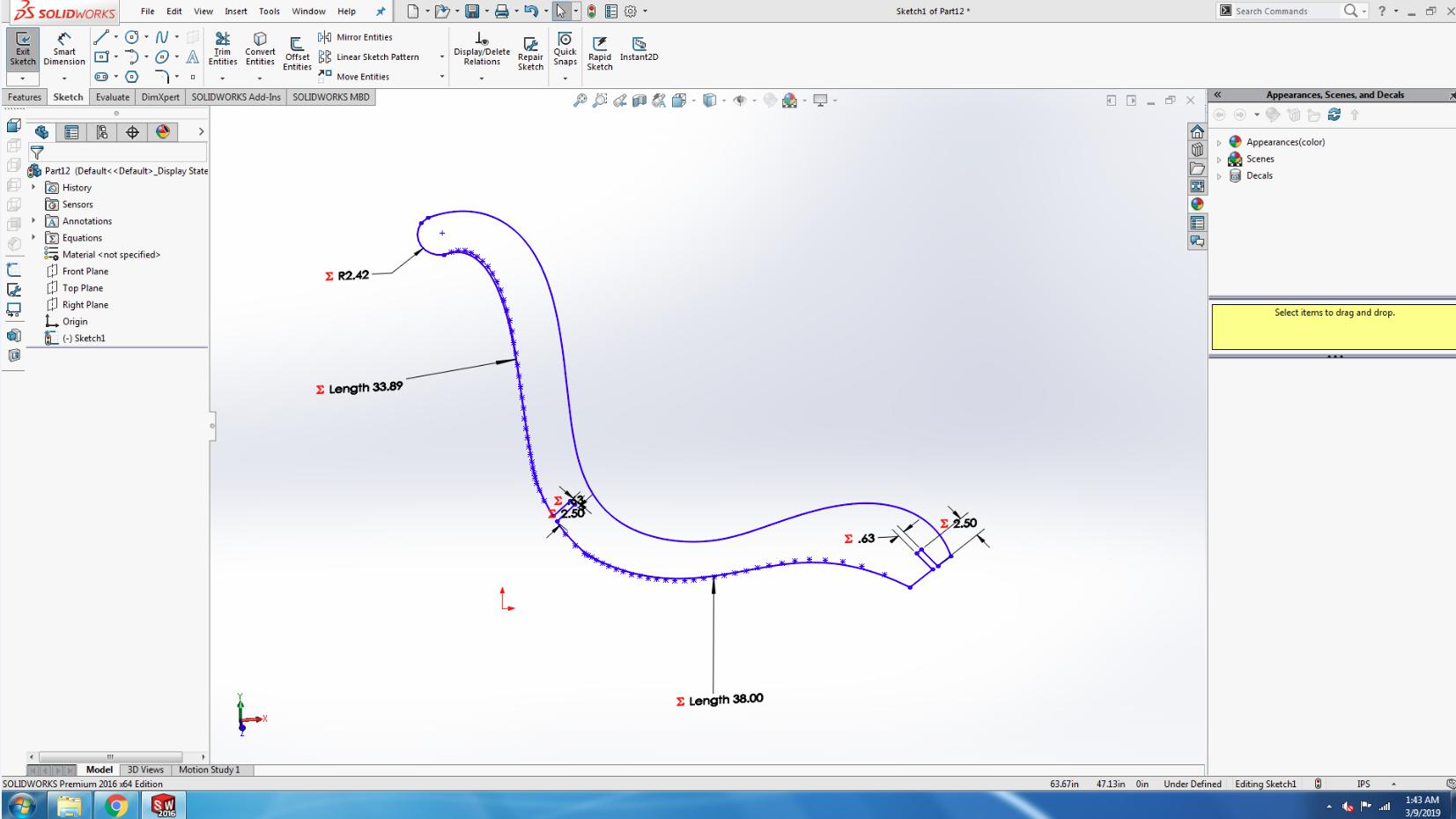
Click on the spline command.
Make a design for the chair.
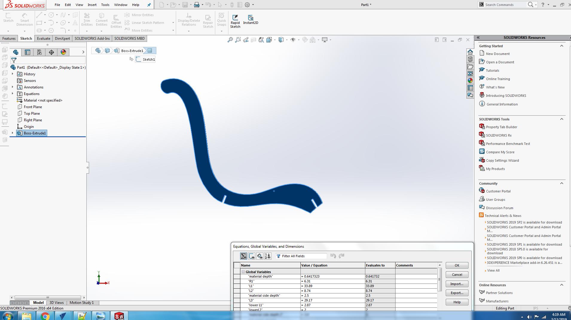
Go to the features and extrude it.
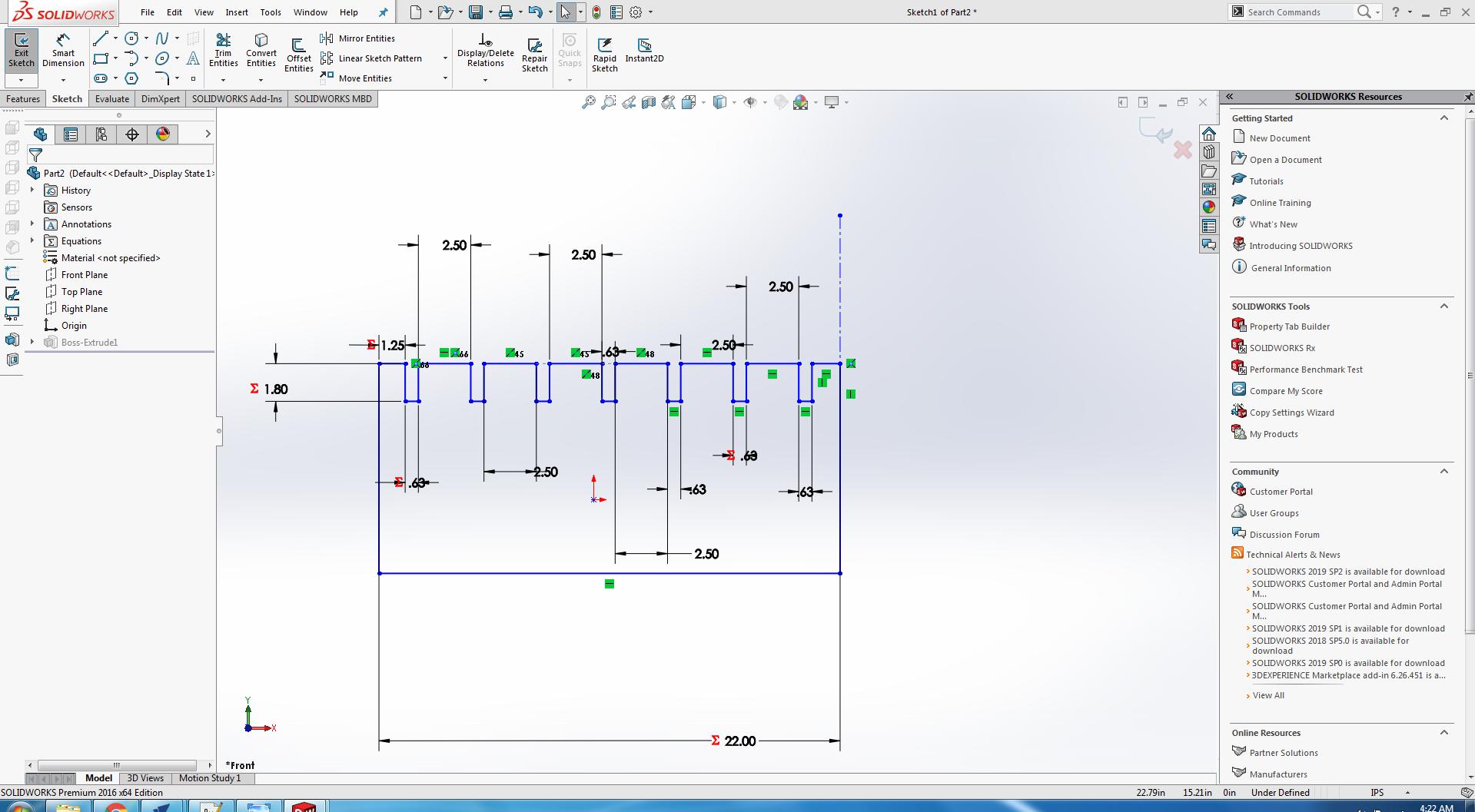
Then make the second part of chair.
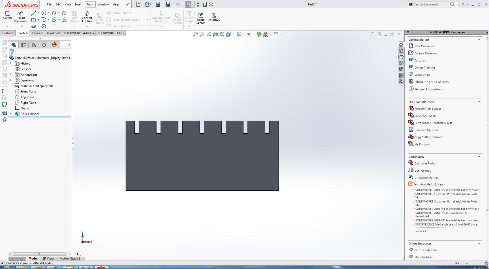
Extrude the second part.
Go to the file and click on the assembly from part.
Import the all parts of chair.
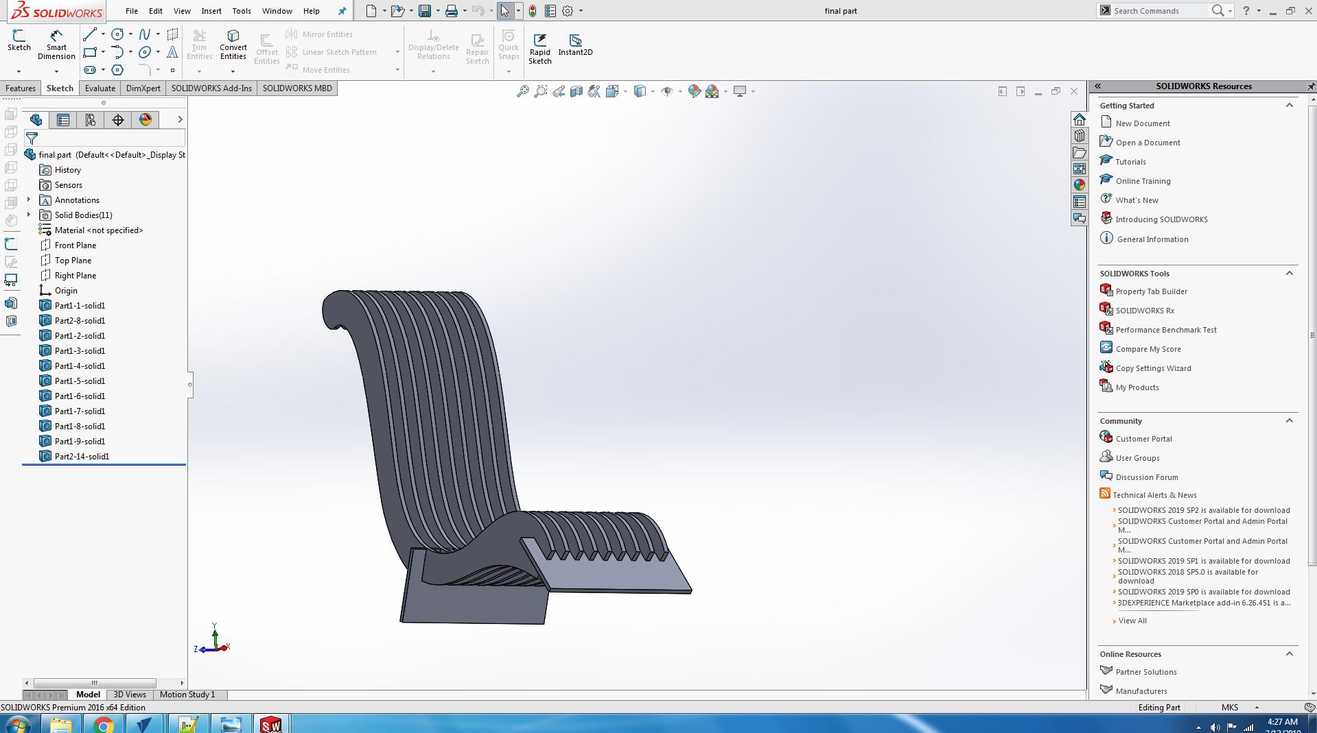
Use the mate command and mate all parts and make a proper chair.
Save this file.
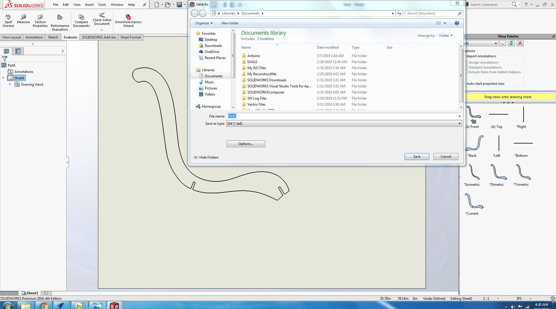
Go to the file menu and click on the make drawing from part.
Set the ratio 1:1 and unit.
Set the drawing on the sheet.
Save the drawing as .dxf file.
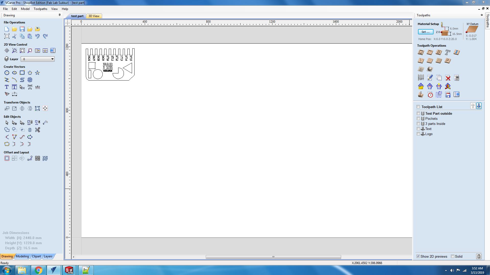
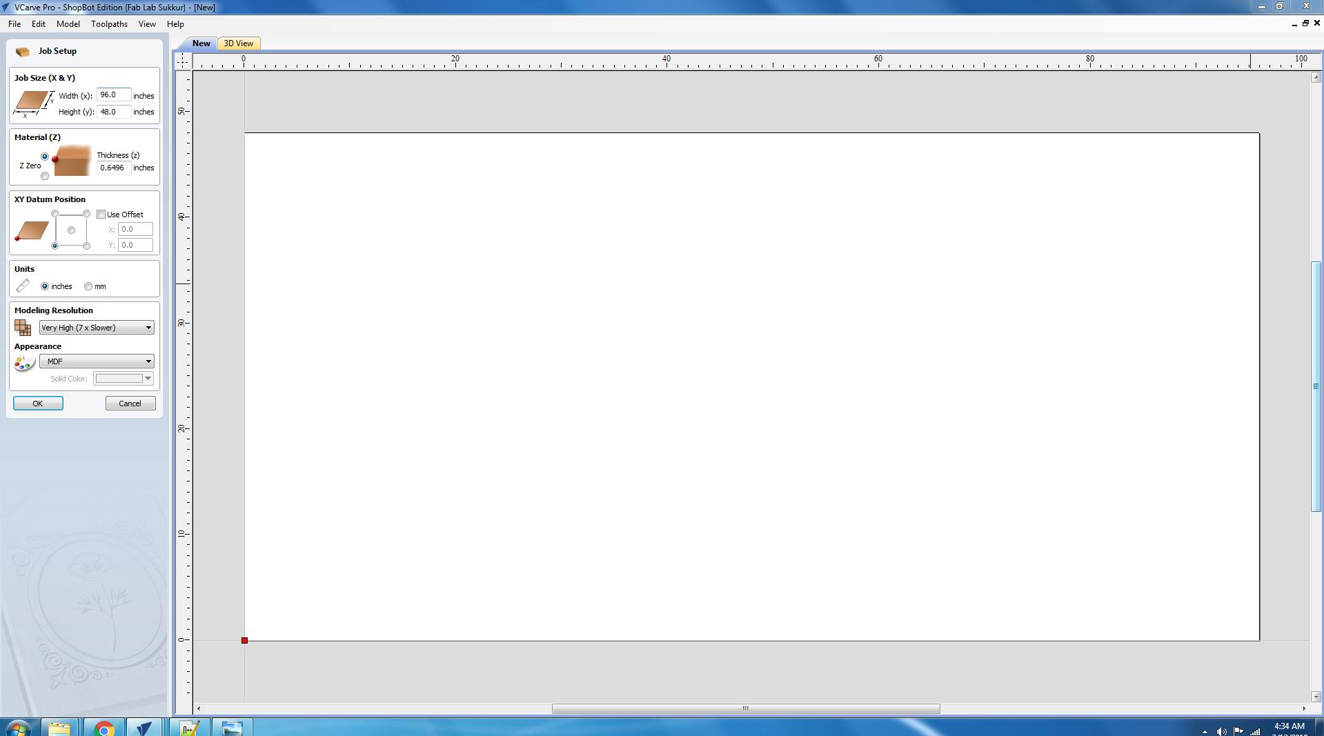
Open the Vcarve.
Go to the file and click on the new.
Set the X,Y and thicknesss of the sheet.
Press ok.
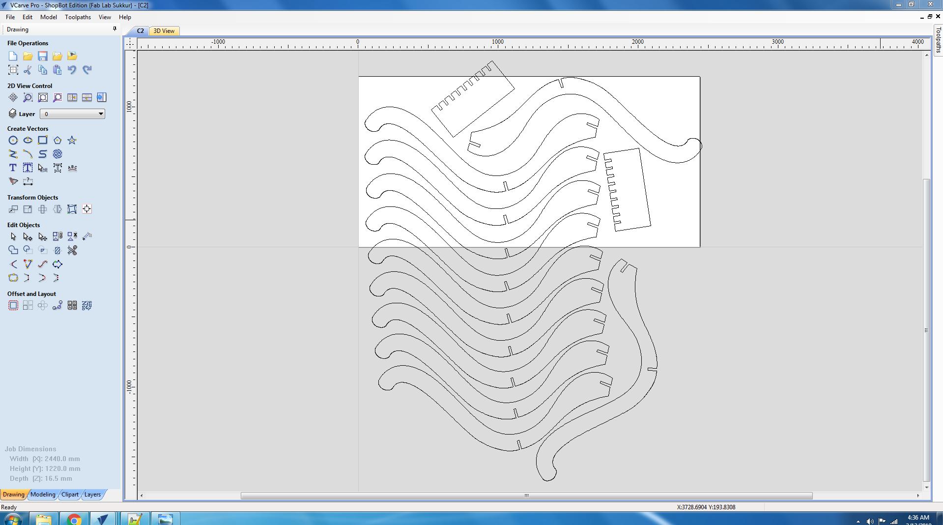
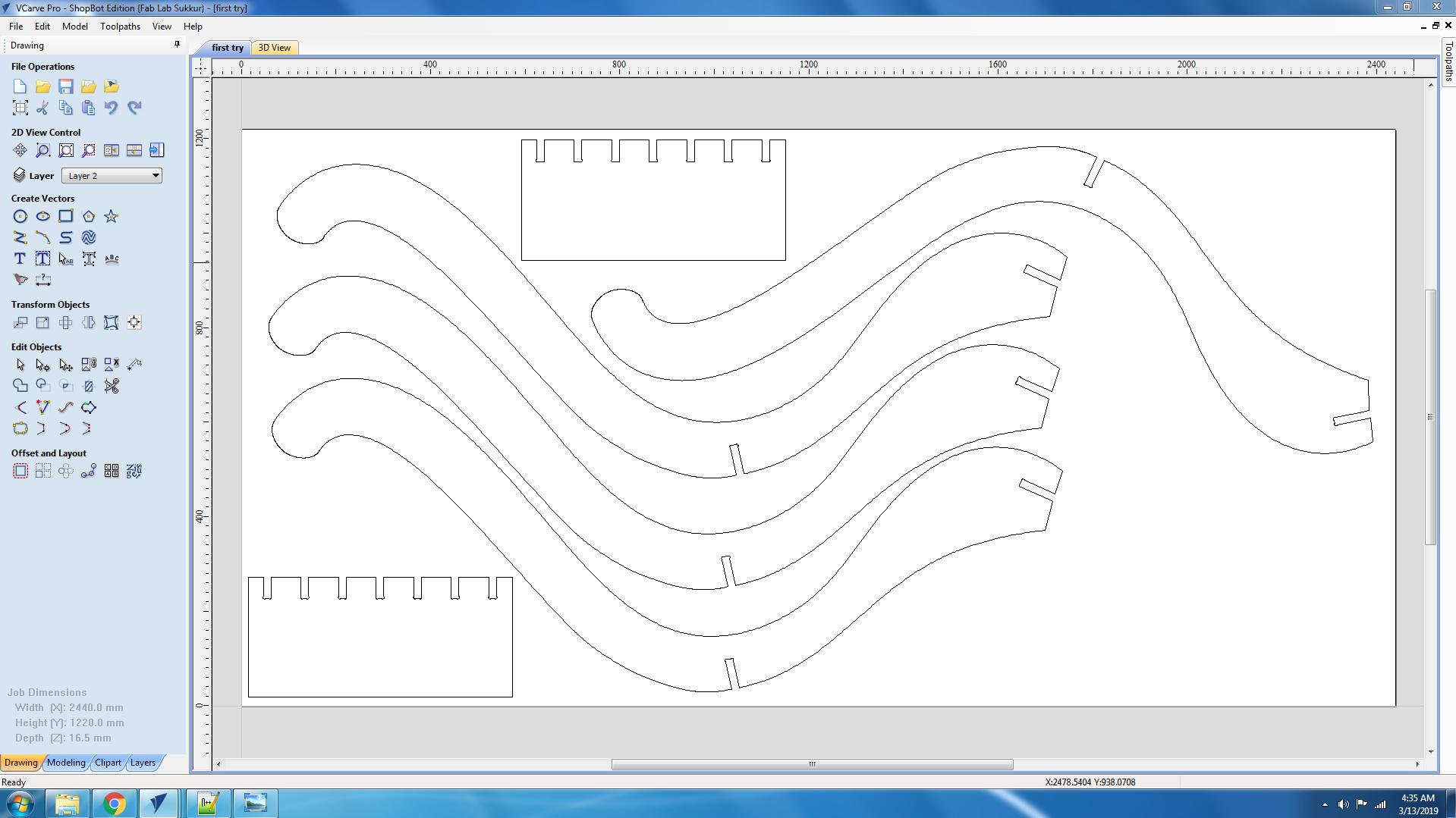
Import the .dxf file in the Vcarve.
Place the all parts accuratly on the bed.
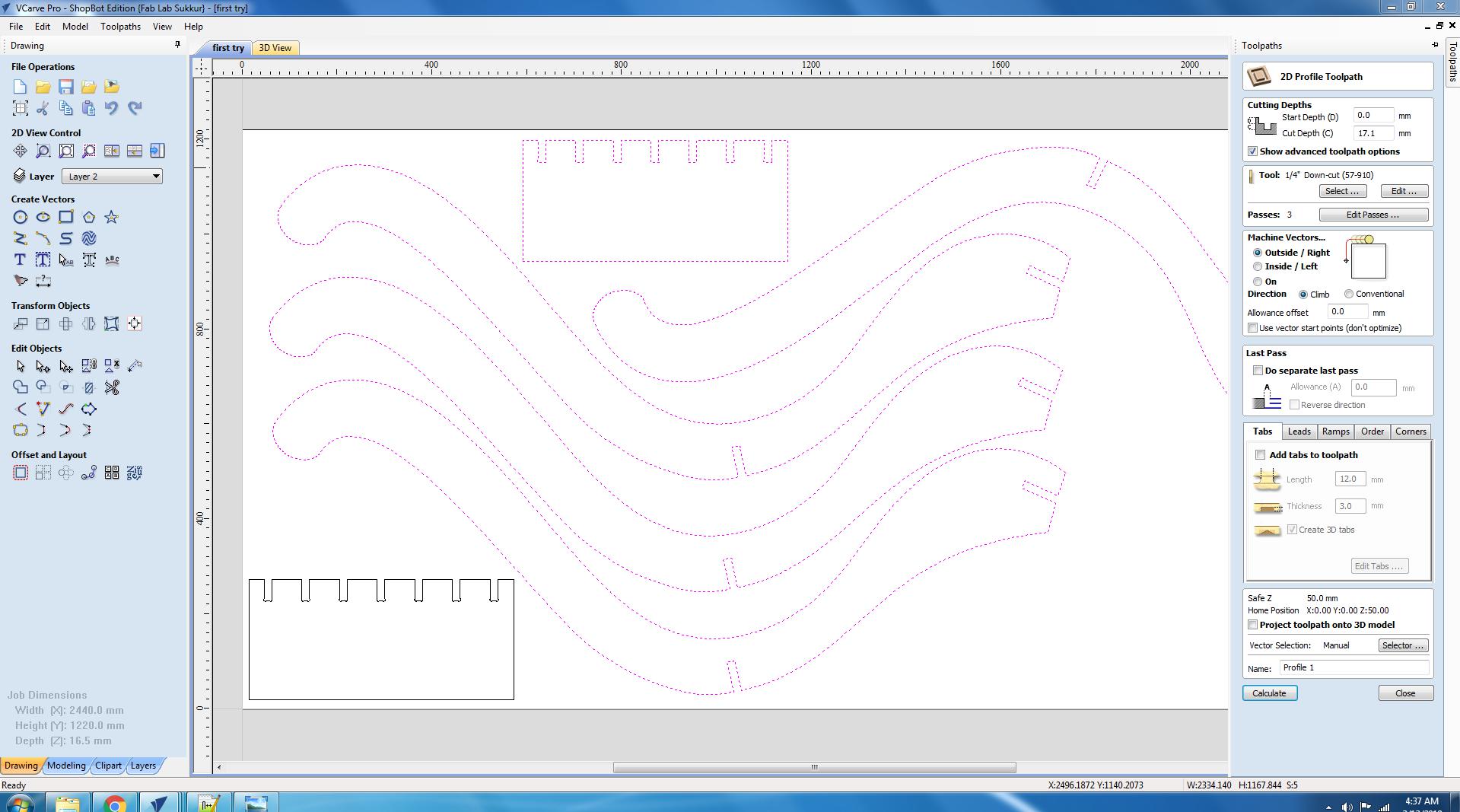
Click on the toolpath.
Select 2D profile toolpath.
Set the Cut depth, Tool, Machine vectors.
Edit the tabs where you need to hold/grip the part during cuuting.
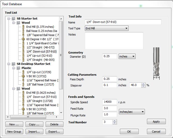
In the above image you can see the values of rpm,feedrate, stepover ,tool-diameter etc. basically these are the by default values and in our lab we mostly operate the machine on these values
, so for I did follow these values and operate the machine and the result was completely accurate. So for we did cut the test part on these by default vales and also cut the final part on these values.
Tools/Commands we used:
Job size:_2440mm and1220mm
Appearance:_MDF
Command: Join
Command: Move
Toolpath: Profile toolpath
Start depth: 0.0
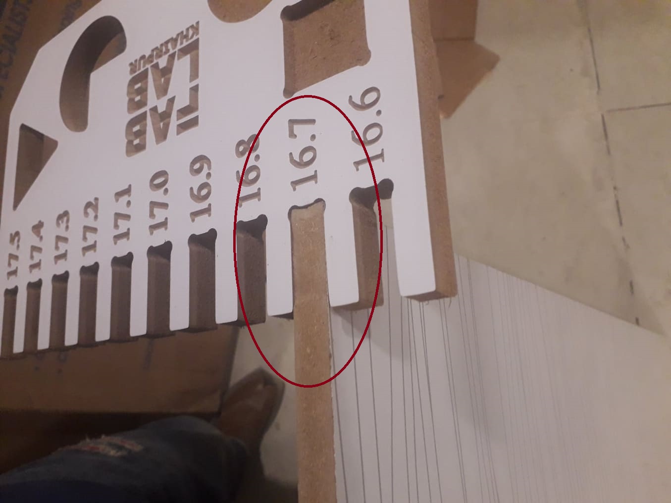
Cut depth: 17.1mm
Tool: 1/4" Down-cut
Machine Vector: Outside
Tabs: Edit
There are three types of mechine vector cut:
OUTSIDE CUT:It cuts from the outside of the boundery/ limits that you have designed.
INSIDE CUT:It cuts from the inside of the boundery/ limits that you have designed.
ON CUT:It cuts from the On of the boundery/ limits that you have designed.
Inside corners that result in a radius are a commonly overlooked issue when designing a part for machining. As of yet, there isn’t a magic way to
cut a corner on a CNC router with a sharp 90º corner. This is because all CNC bits are round.Depending on your project, internal filleted corners may not be an issue for
you. For some, this means your joints won't fit and you need a nice square corner.
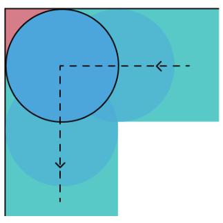
Inside Corner problem.
HOW TO FIX THIS PROBLEM??
The solution is to modify the design to compensate for this problem. W eare using Vcarve, there is a tool that will do these operations automatically.
T-BONE:There is another way to cover that area, though. Instead of 'pushing' a circle into the corner of your design, you can push a circle directly in one direction, up or sideways.
The math for this method is simpler: you only need to push a circle up by one radius from the corner.
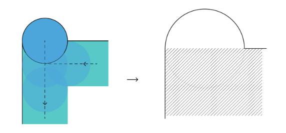
T-BONE
DOG-BONE:Dog bone corners are a jargon-y way to describe the shape of a corner that is extended outside the cut area to create a perfect 90º corner that looks like the cartoon shape of a canine chew
toy.We used dog-bones for this problem in the design, For this command we have to just click on the filletcommand from the edit objects menu and from there we can select dog-bone and edit the object's corner.
For further understanding you can click
HERE .
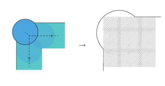
DOG-BONE
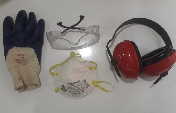
The tools we used for the safety precautions are the dust mask, earmuffs, safety glassess and gloves.
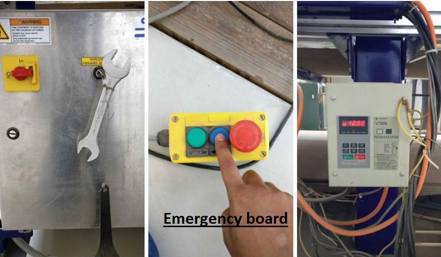
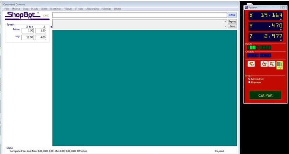
Shopbot software
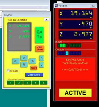
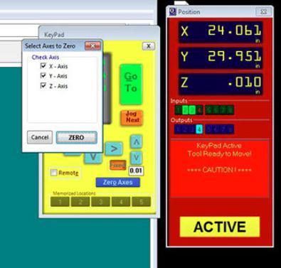
Setting the origin
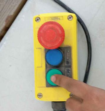
Emergency board
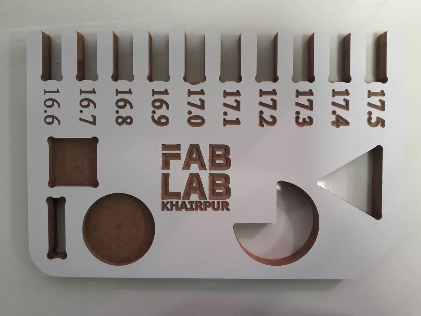
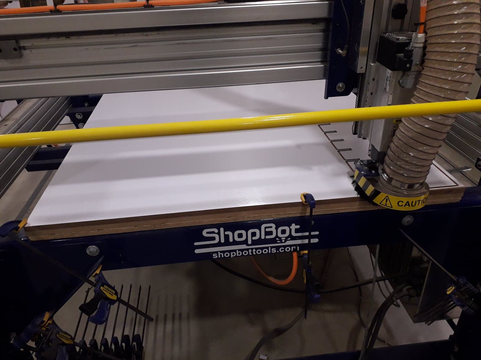
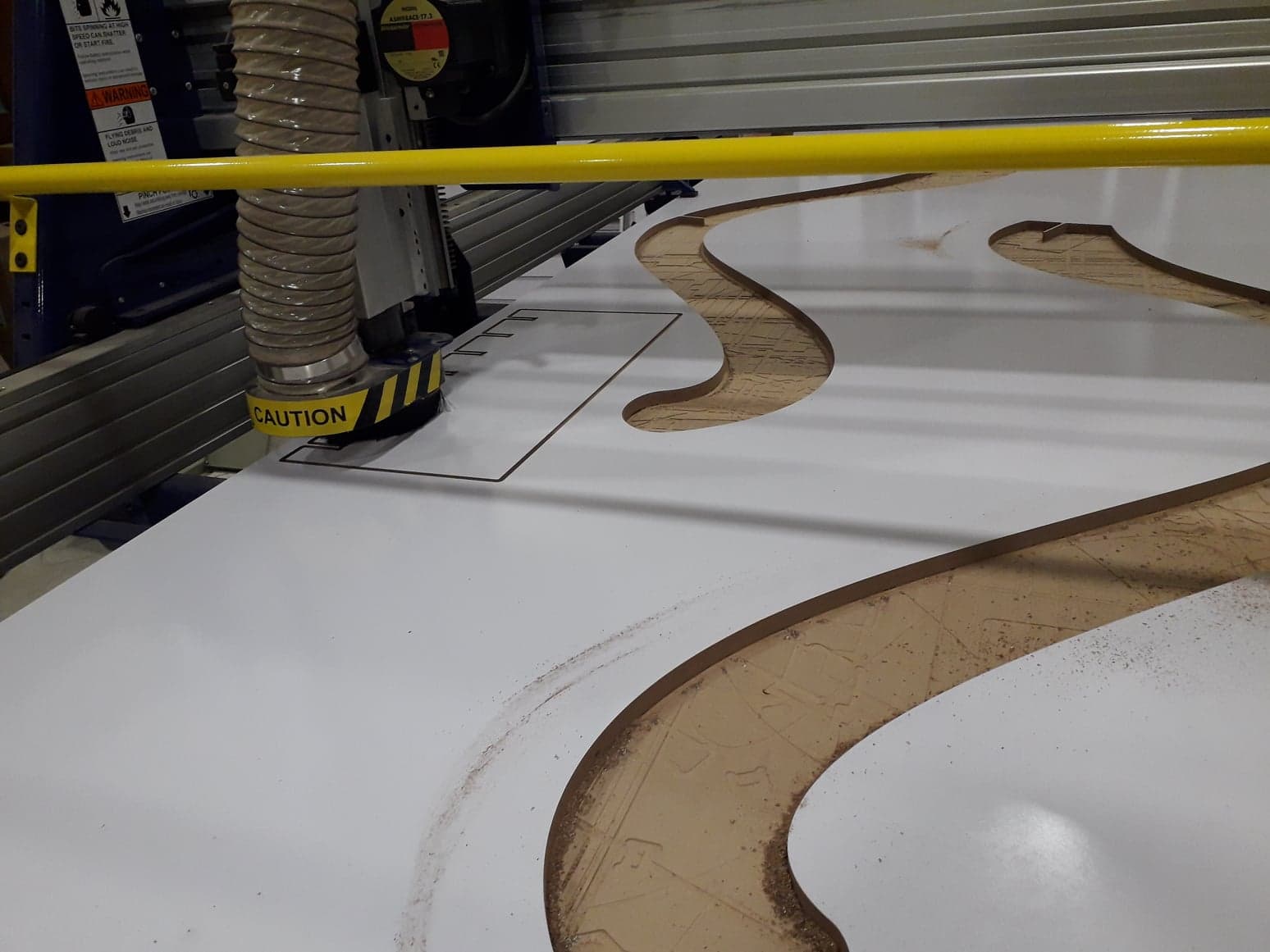
Finally the machine is going to cut the part.
I place a MDF sheet(length=8feet, width=4feet)on the machine bed and made setting according to my need and Machine.
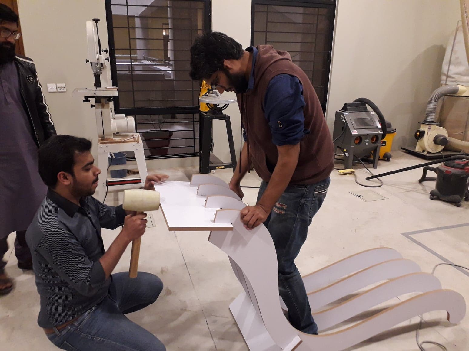
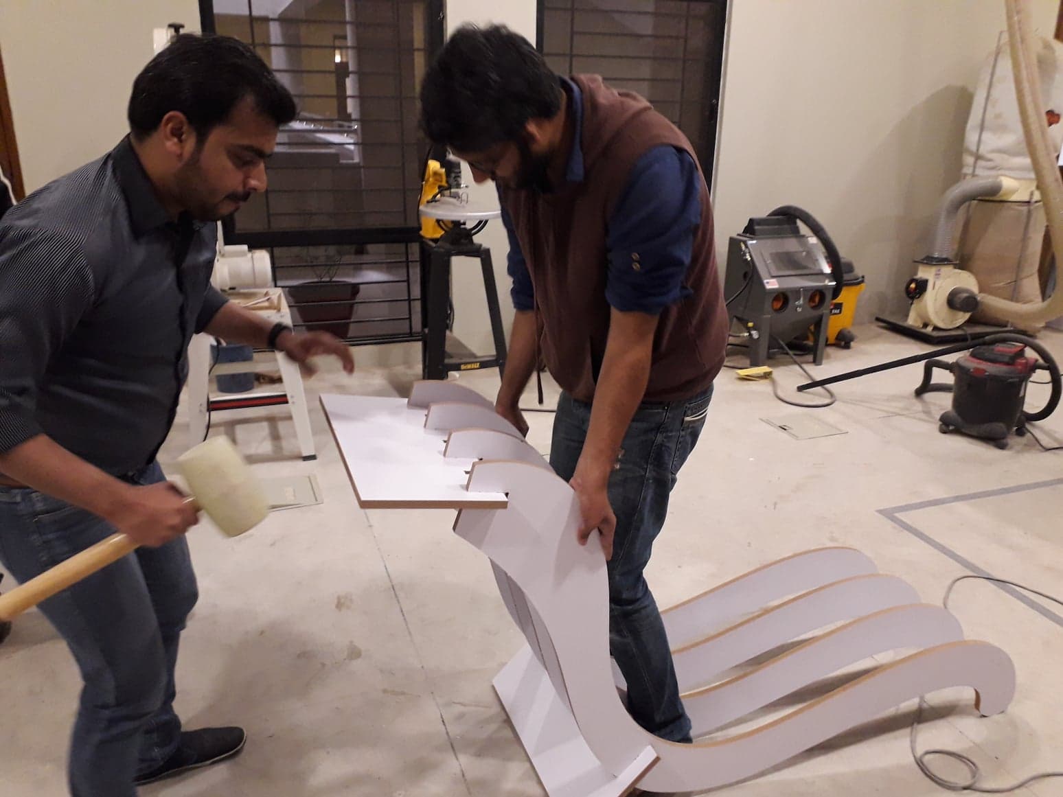
Now the parts are ready and we making assmbly of the parts,In all these
Mr Rasheed qazi(local instructor of Fab lab Khairpur) help me alot and also help me in assembly.Thanks Mr Rasheed Qazi.
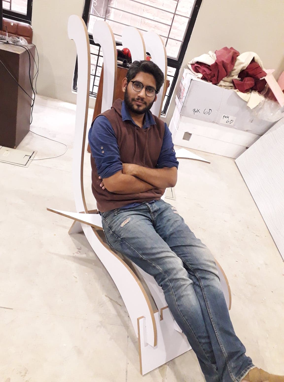
Now the chair is ready and I am relaxing on it.