Final Banner
My Final Presentation Video
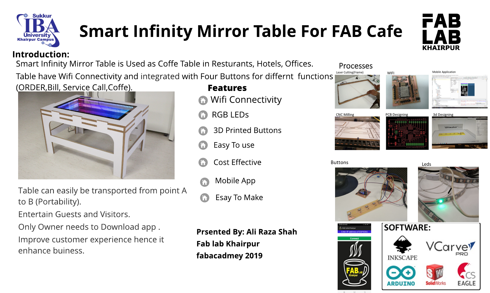
This week I worked on defining my final project idea and started to getting used to the documentation process.
When I saw the infinity mirror effect for the first time, I was impressed with itI wanted to build my own version of it,
and so, I decided to use Infineon's 3D magnetic sensor kit with the rotator knob to control colors on an infinity mirror table with an RGB LED strip.
An infinity mirror creates a striking optical illusion - a tunnel of light that seems to tear through space.
I built this infinity-mirror table using some addressable LEDs, a Particle Photon and easily obtainable timber supplies.
The idea i got from the fab lab 2018 student sarah costan in which she made infinity mirror room. I'm inspired from her idea and i decided to make this in the form of table .This idea is applicable anywhere we want e.g Hotel , resturant , Home , offices. Therefore i have decided to add some features in this table like i can install music player in it when person so tired he/she can play relaxation music and enjoy the moments. There are many ways to connect your smartphone to an embedded microcontroller. In this project i will use an Android phone in USB host mode because these tables can be used everywhere like home , hotel etc. So we can get advatage of that smart table.Apart from that we can put things on it like wallet , key , Mobile etc.
literature Review
How does an infinity mirror work?
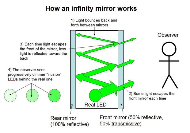
How It Works
Not surprisingly, there is no magic involved. The secret is that the infinity mirror actually contains two mirrors with different transmissivity and reflectivity.
For all practical intents and purposes, mirrors that we deal with in everyday life are 100% reflective (technically a tiny amount of light will also be absorbed, but we can ignore that for now).
That’s the regular mirror at the “back” of the infinity mirror (on the left in the diagram above).
The tinted window film, however (on the right in the diagram above), only reflects about half of the light that hits it*. This means that, when you sandwich an LED between the two mirrors,
some of the light escapes through the front mirror and into your eye. The rest is bounced back off the rear mirror,
then into the front mirror again, and this process continues off to infinity – thus the name. But, since a little bit of light escapes each time, each successive illusionary LED that you see will look a little bit dimmer, until they gradually disappear – you can’t actually see infinitely many LEDs.
Note that this does not work because the window tint “only lets light through in one direction”, which is a common misconception.
In order for the illusion to work properly, the side of the front mirror the observer is on (the outside world) must be much darker than the side with the LEDs (inside the infinity mirror). This is the same effect that you see in crime dramas/movies where someone is held in an interrogation room that has a mirror on the wall, but there are people on the other side of that mirror observing as though it’s just a window. That only works if the interrogation room is well-lit and the observation room is dark.
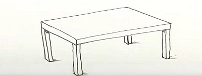
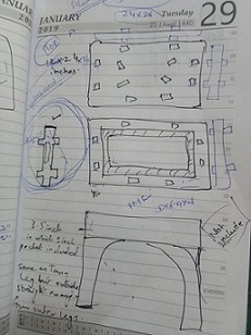
Initial Sketch
After table the next step is to make infinity mirror
1.Find a suitable wooden frame. Preferably get something with a deep frame or at least 1/2 half inch depth.
2.Disassemble the frame and remove the glass.
3.Prepare the glass by making it perfectly clean.
4. Spray the glass with a little water and a drop of wash liquid.
5. Take the roll of window film and cut a piece a couple of inches bigger than the mirror.
6. Remove the backing from the window film.
7. Lay it over the glass pane. Starting from one corner, spray some liquid soap as you slowly lay this over the glass. Smooth out any bubbles and leave to dry.
8. Once dry leave to one side for later.
9. Obtain a mirror with the same size as the framed glass that was tinted. As an option, get a mirror in its frame and make another frame to go over the original to give more depth with the wooden splines. about 2.5 inch (6.4 cm) to 3 inch (7.6 cm) is ideal for this.
10.Assemble the framed glass you tinted, make sure the tinted area is facing the inside of the frame.
11. Secure the tinted glass with glue.
12. Add a inner frame to hold the mirror when it is placed on lights.
13.Using a cutter, create a groove for the LED wirings and adapter.
14. nstall the LED lights around the inner frame. Drill holes big enough for the lights to push into on the frame you just made. about halfway in the width of the wood and evenly around the entire frame.

Mirror
LED Strip
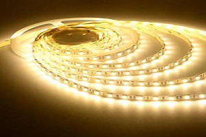
LED Strips
Black paint For Frame
Black paint
Solar Film For Glass
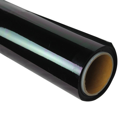
Solar Film
For this assignment I decided to make table . As I mentioned in Week4 Computer-controlled Cutting The design of week4 will help me in Week8. in week 4 i design a test part of the table , But here is the first step towards my final project .So intially i started work on sketch of the table where i discussed with my local insrutors Mr.Soahil Ahmed Somroand Mr. Noor Ahmed Pirwani.After discussing i started make sketch of the table in board and also tried on paper to clear sktech in my mind.
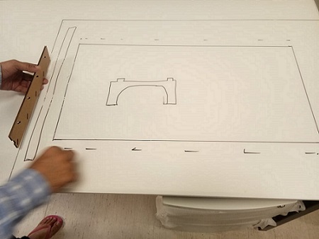
Sketch On Table
Anoher view
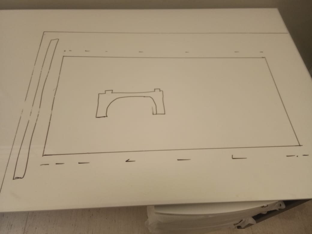
After doing this the next step i did is draw sketch on paper to clear my mind about design.Like how it looks like after designing etc.
Sketch On paper
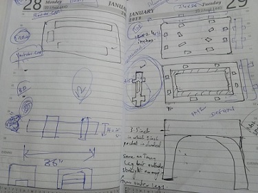
Sketch On paper
As i already mention that i have design test part of the table in week4 , So in this week I actually implementing that test part using CNC milling (Shop Bot). just i have to make that design accordingly , and setting things according to CNC Milling .
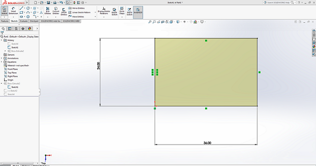
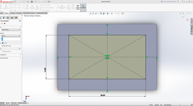
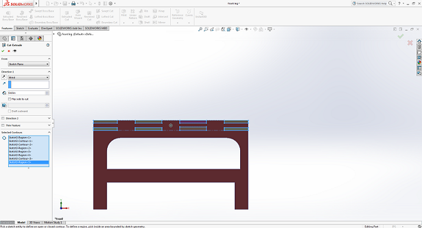
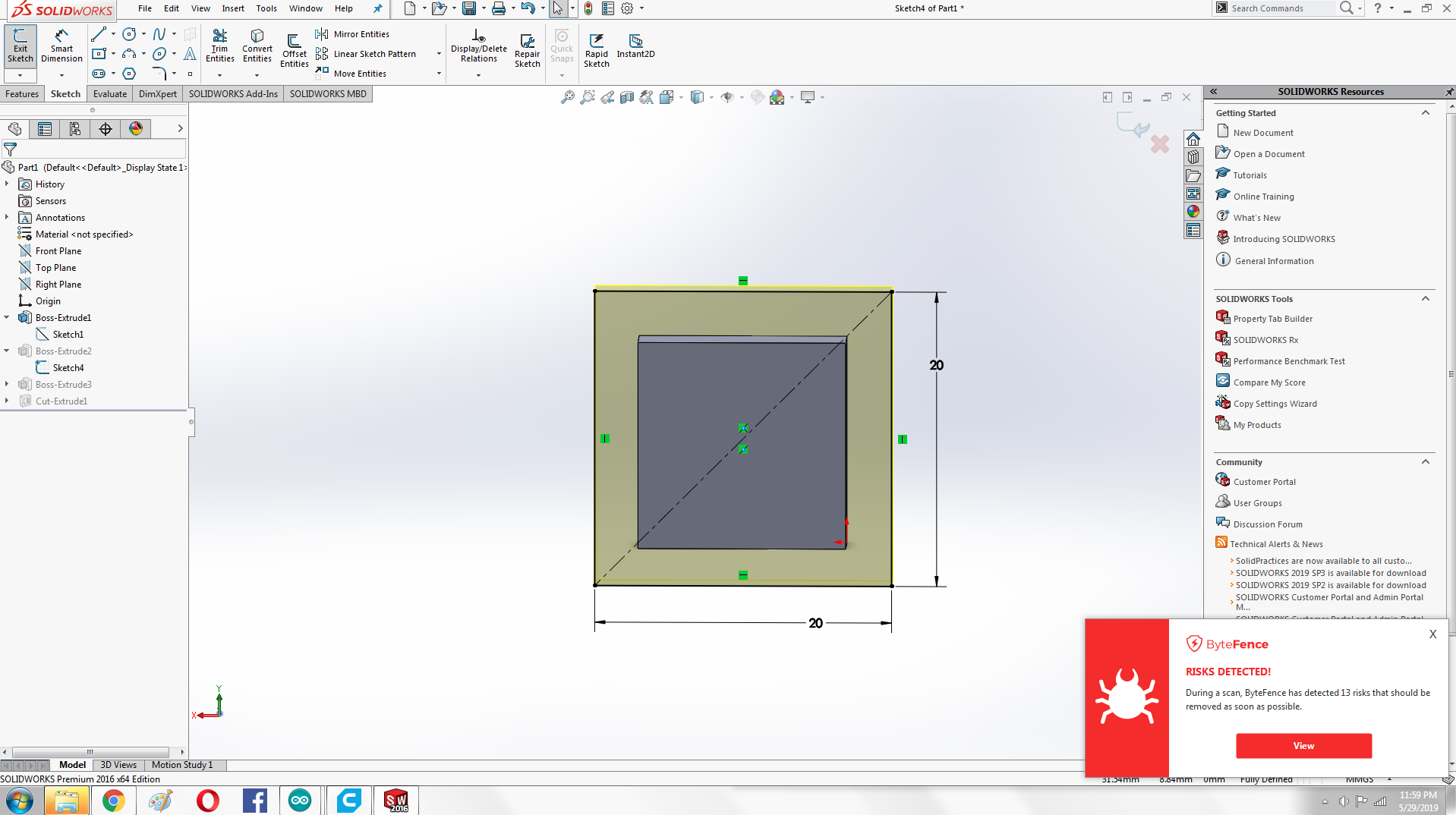
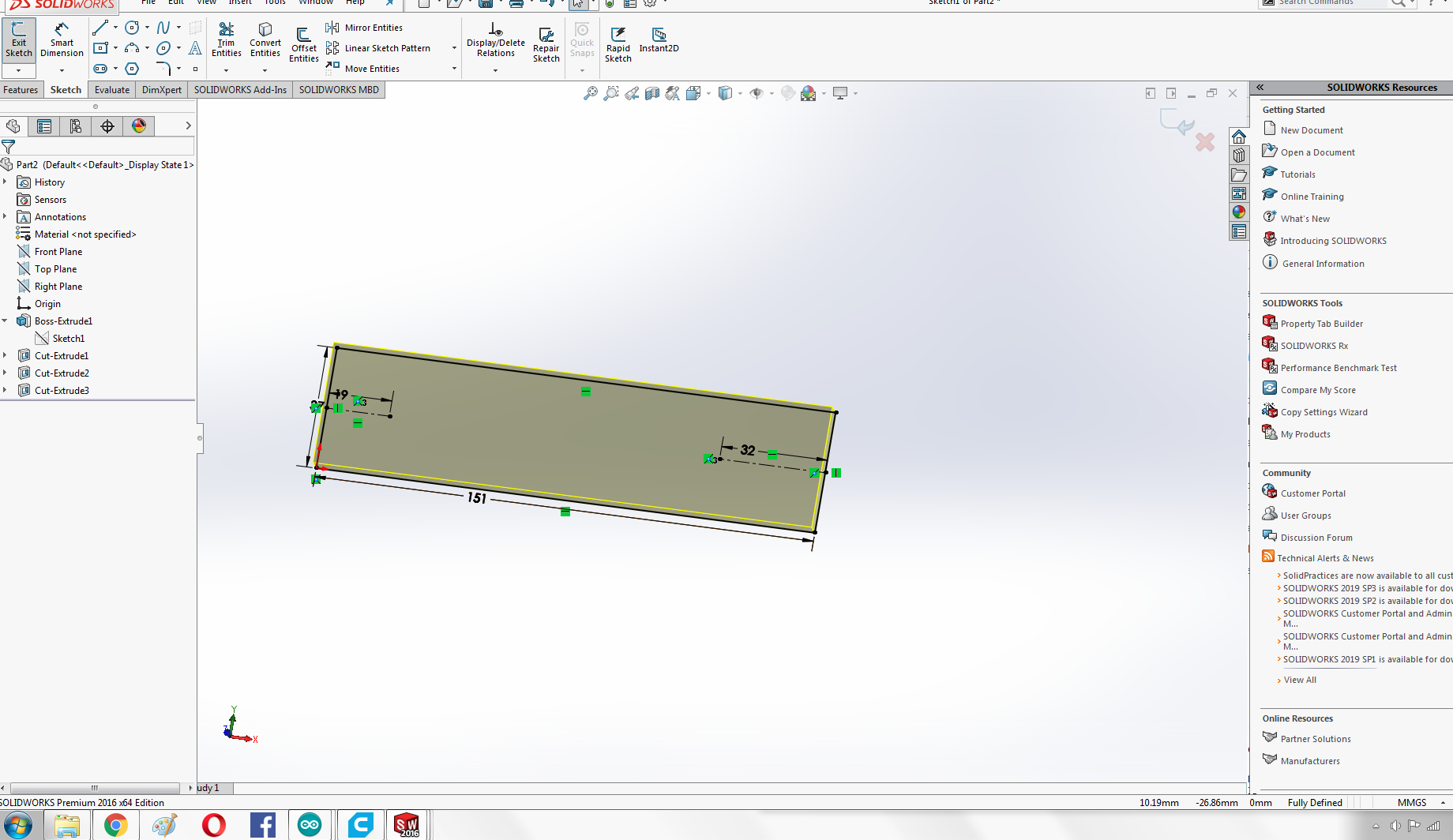
Defining The Dimensions
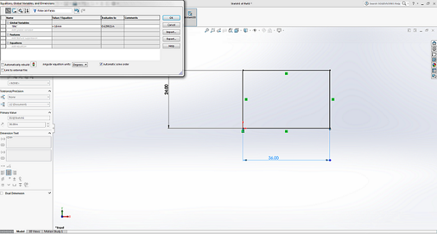
Definig Parametric Equation
Definig the thickness parameter as variable. I defined global variable name "thk" value 16mm according to the material thickness.
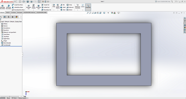
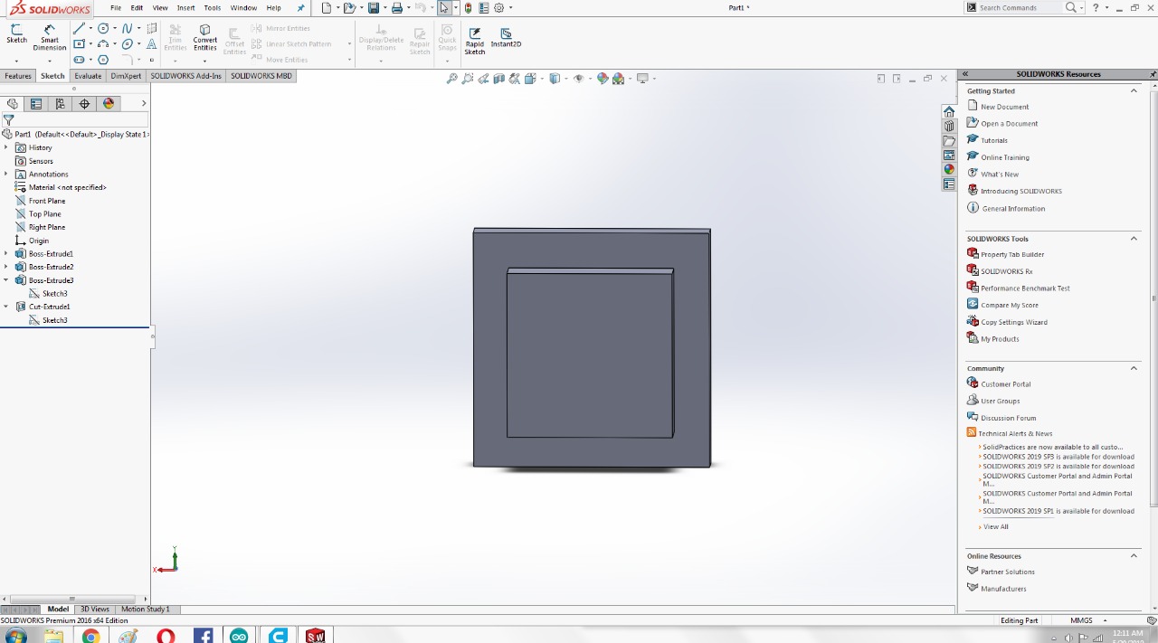
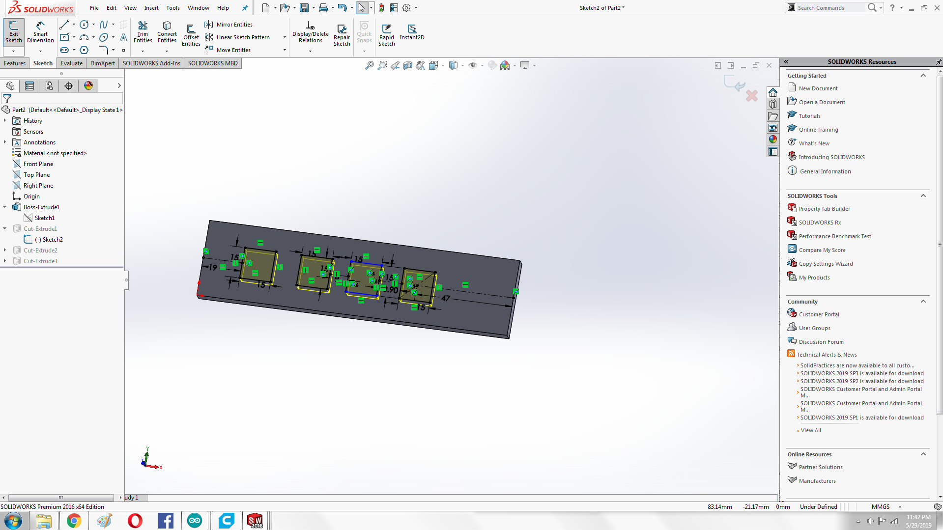
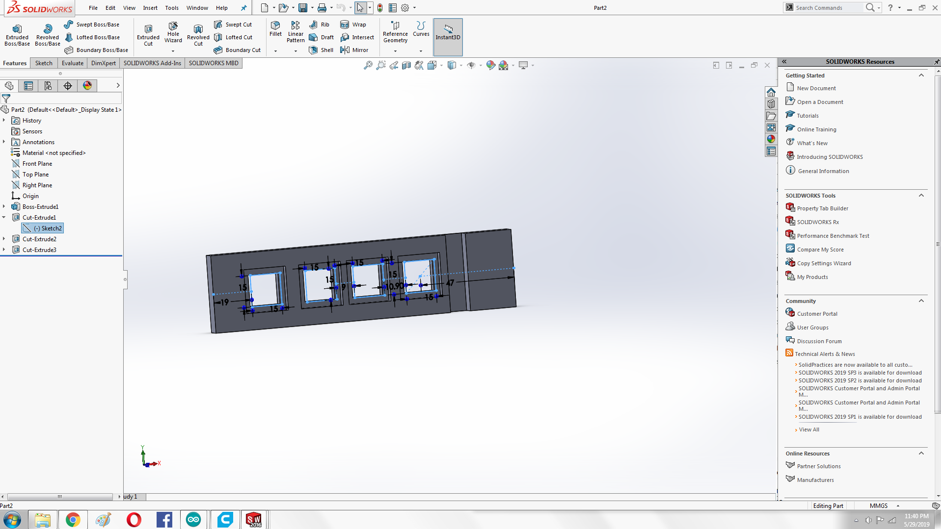
After Extrude Cut
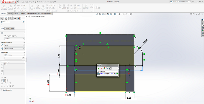
Side leg
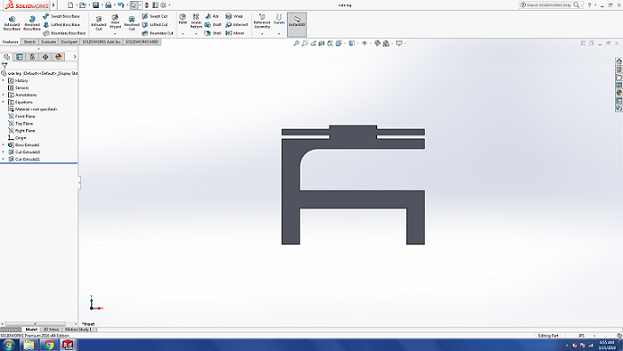
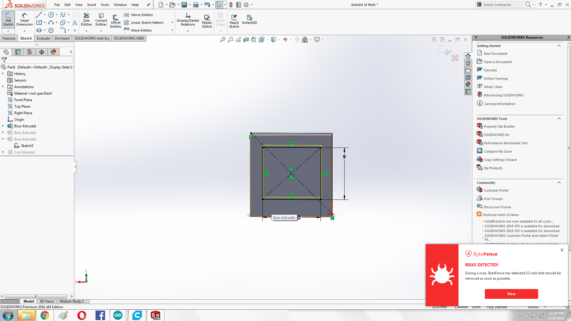
After Extrude Cut
cuting outside from top
I did this by using the tool mirror entities.
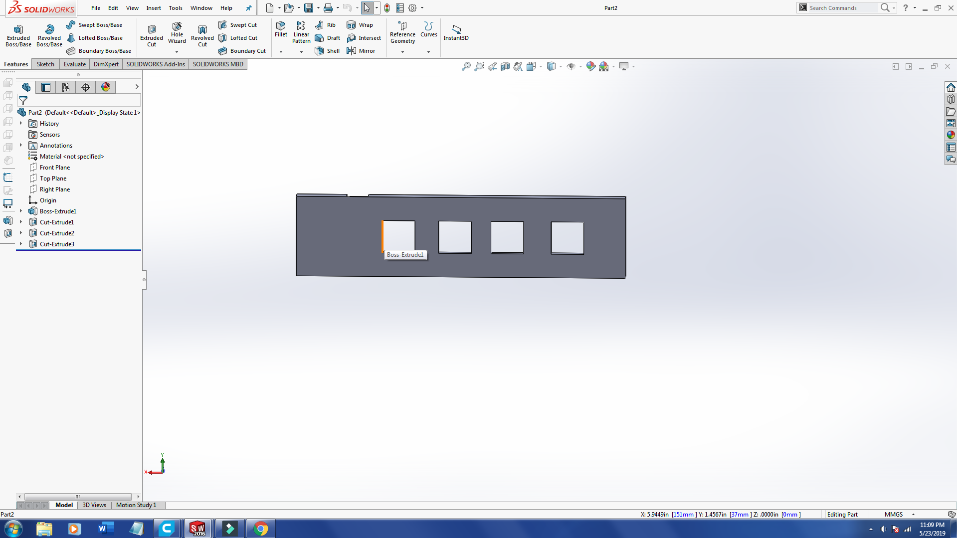
After Extrude Cut
Base
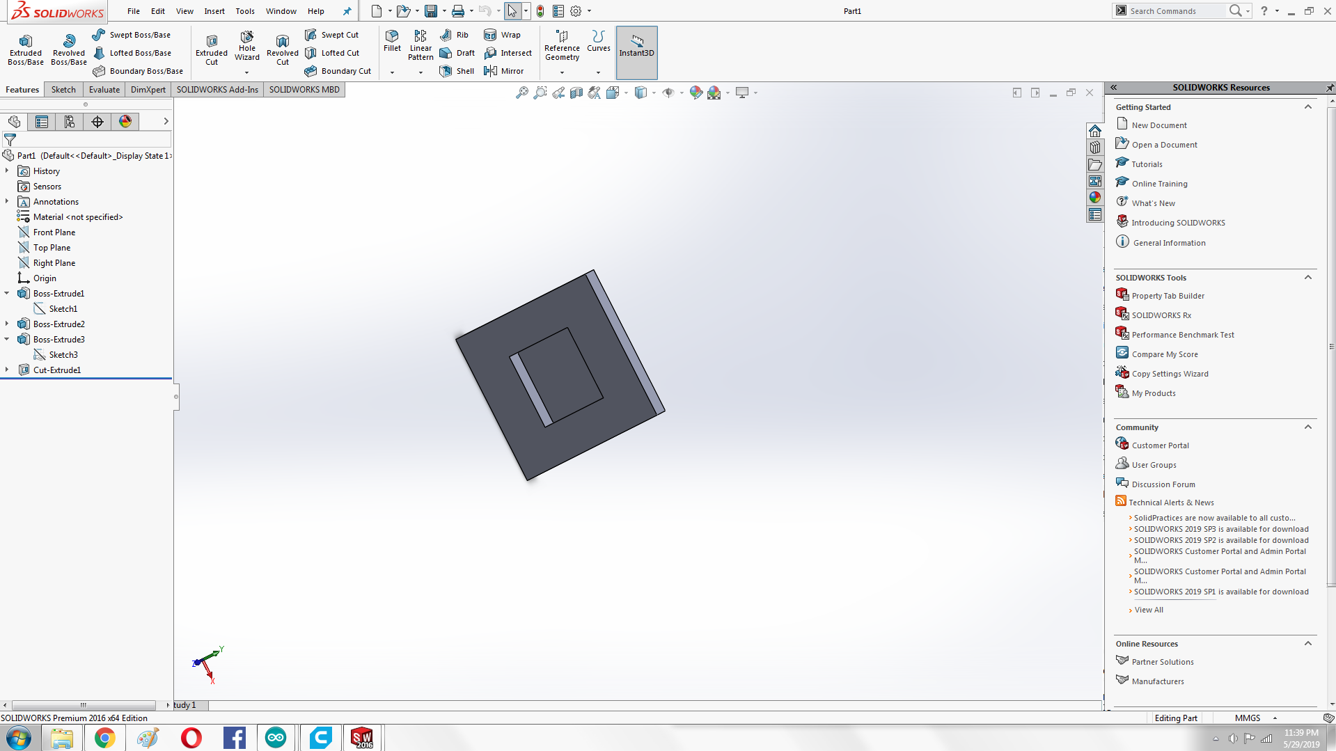
Now the next step is to make side legs from other side that is little grater than previuos side .
Base
Extrude Cut
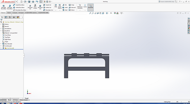
After Extrude Cut
Now all the components are ready the next step is to assemble them . All Compoenets are put into assebly file where i mate all components.
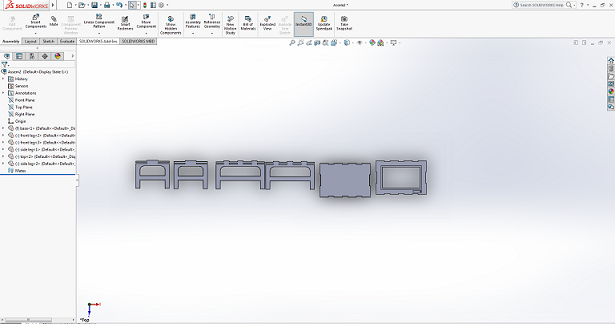
All Components are in Assembly
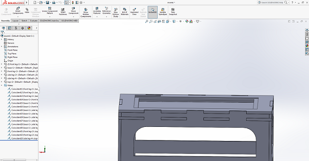
Final table
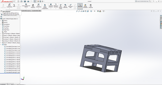
Another View
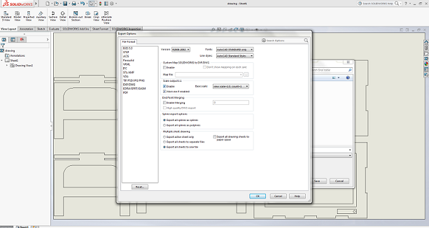
After succssfully doing assenbly the next step i did i make drwaing from assebly file , for dfx file
Making Drawing
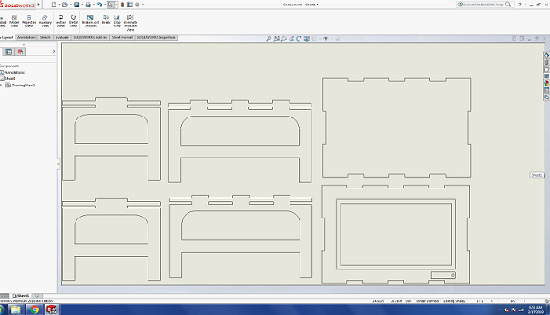
Making Drawing
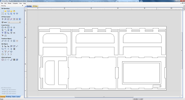
The Next step afer dfx file is to generate G_code for shopbot machine for this i used Vcarve. Where intially i setting design according to the material size that we have and te toolpaths according to the design. After that i performed joining and dog bones repectively.
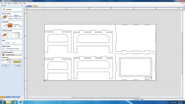
Adjusting the components
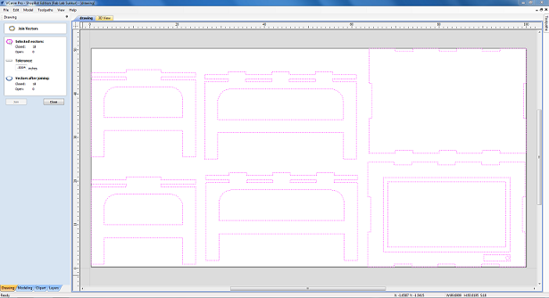
Joining
DogBons
After Generating G-code the Next step is to finaly start cutting with Shopbo. Before doing that we need to make sure that the tools that we used according to the design and toolpaths that we generated or not if not so we need to change it. I used two tools one for writing fab lab khairpur name in legs of the table and second for other design
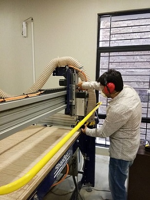
While Changing Tool
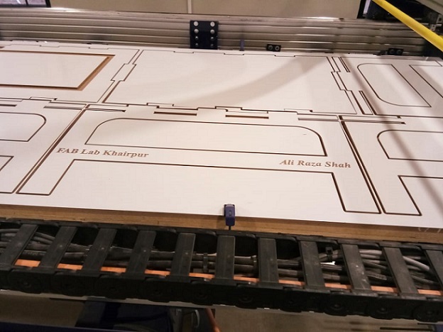
After changing tool i ready the job for CNC machine. Initially i cut the name that i want in table side and i changed tool accordignly.
Cuting Name
Cuting Name
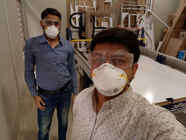
With Local Instructor
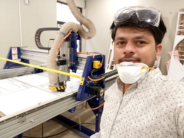
Selfie :-)
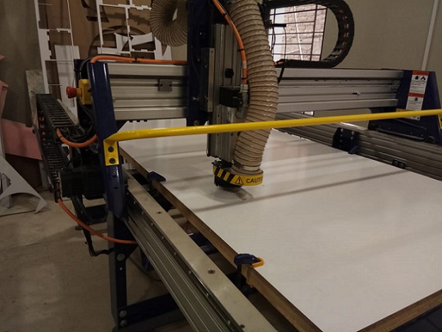
After Cutting the name the next step is to cut other compoenets for that i need only one and same tool for cut so i changed tool and given job to machine
Cutting Others part
Cutting pocket
It akes almost three hours to complete this job.Finaly here is the almost complete cut of the design
Almost completed
All parts
After cutting te next step is main and most critical part of the this week assigmnet is asseblig the compoents .I taken almost three hours to asseble the the all components because before doing this we must be careful about the critical parts and sides of the design.
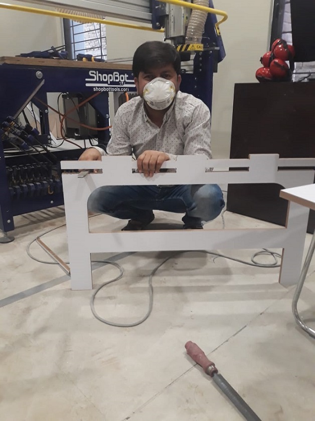
While assembling the compoenets
And here is the final design that is ready.
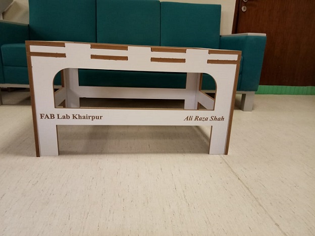
My Table
Top
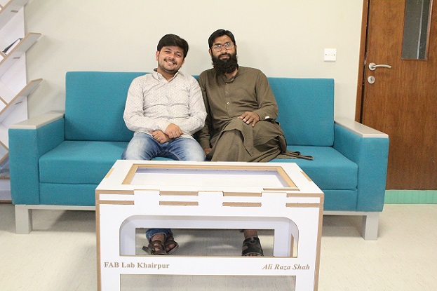
Now Iam Relaexd with Tariq:-)
This weeks assignment was to make a circuit that can control something i.e. output device. To combine this weekly assigment with my final project, the aim of this week is to make boad and connect RGB strips with it, and program it with different effects of lights.So fo this week assignment I decided to make Satshakit and took reference fom Daniel Ingrassia.
After redrawing so much controller boards in past weeks I planned in this week to make my own design, for this I want to make a board which is not only use in this week but kind of general purpose board for me.
I started with designing the board! .Satshakit is a 100% Arduino IDE and libraries compatible, fabbable and open source board, and also an improved version of Fabkit. I used ATmega328p .The ATmega328 is a single-chip microcontroller created by Atmel in the megaAVR family (later Microchip Technology acquired Atmel in 2016). It has a modified Harvard architecture 8-bit RISC processor core.Wikipedia
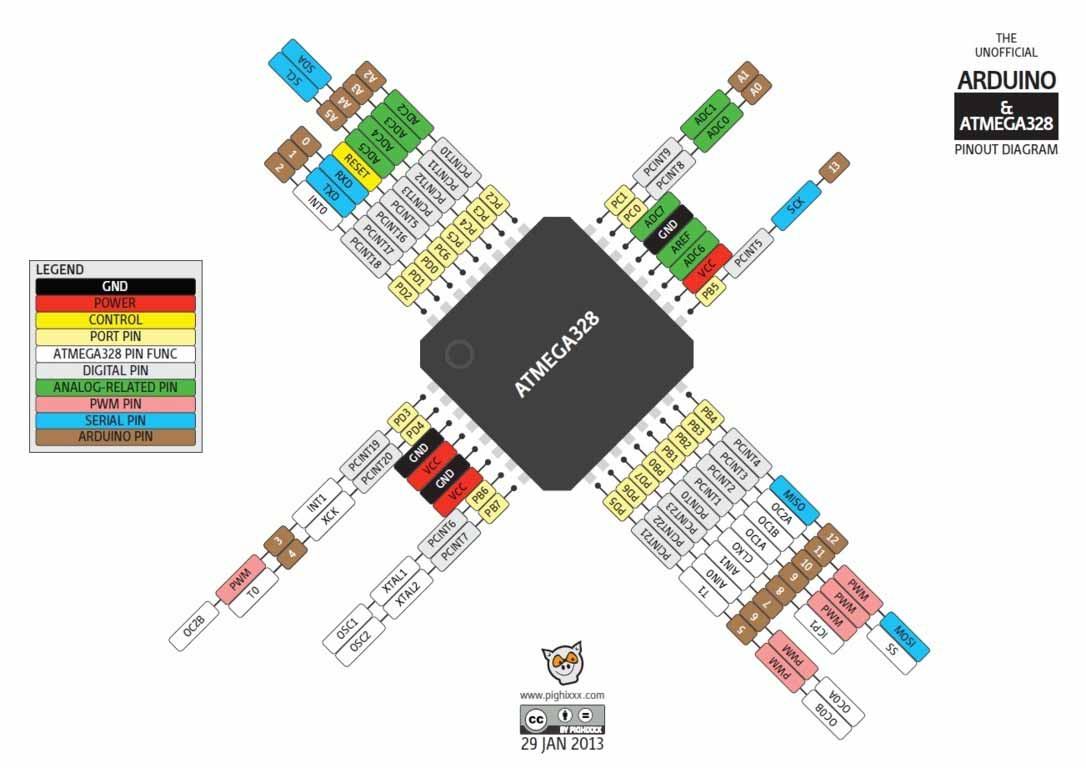
ATmega328
For PCB designing I worked on Eagle 7.5 that I have been using since from Week4. First I made a schematic of board:
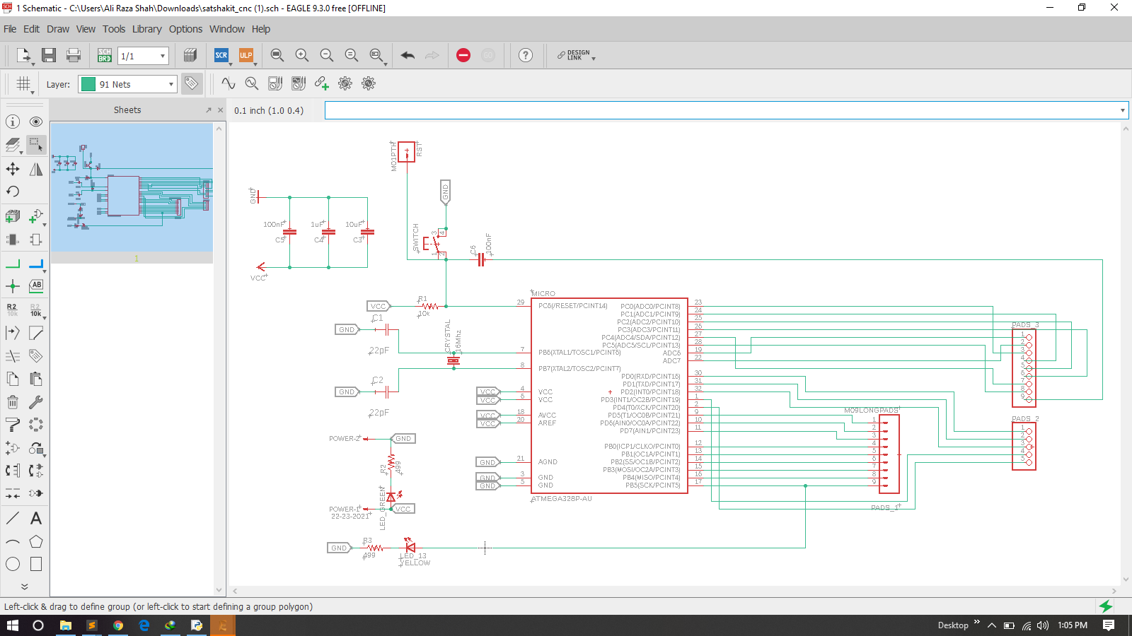
Schematic
After schematic I have generate PCB board and route it as we did in previous weeks .
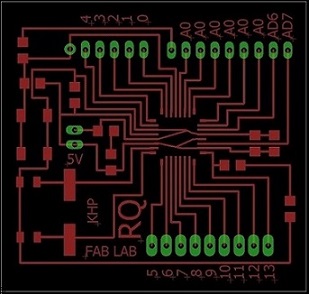
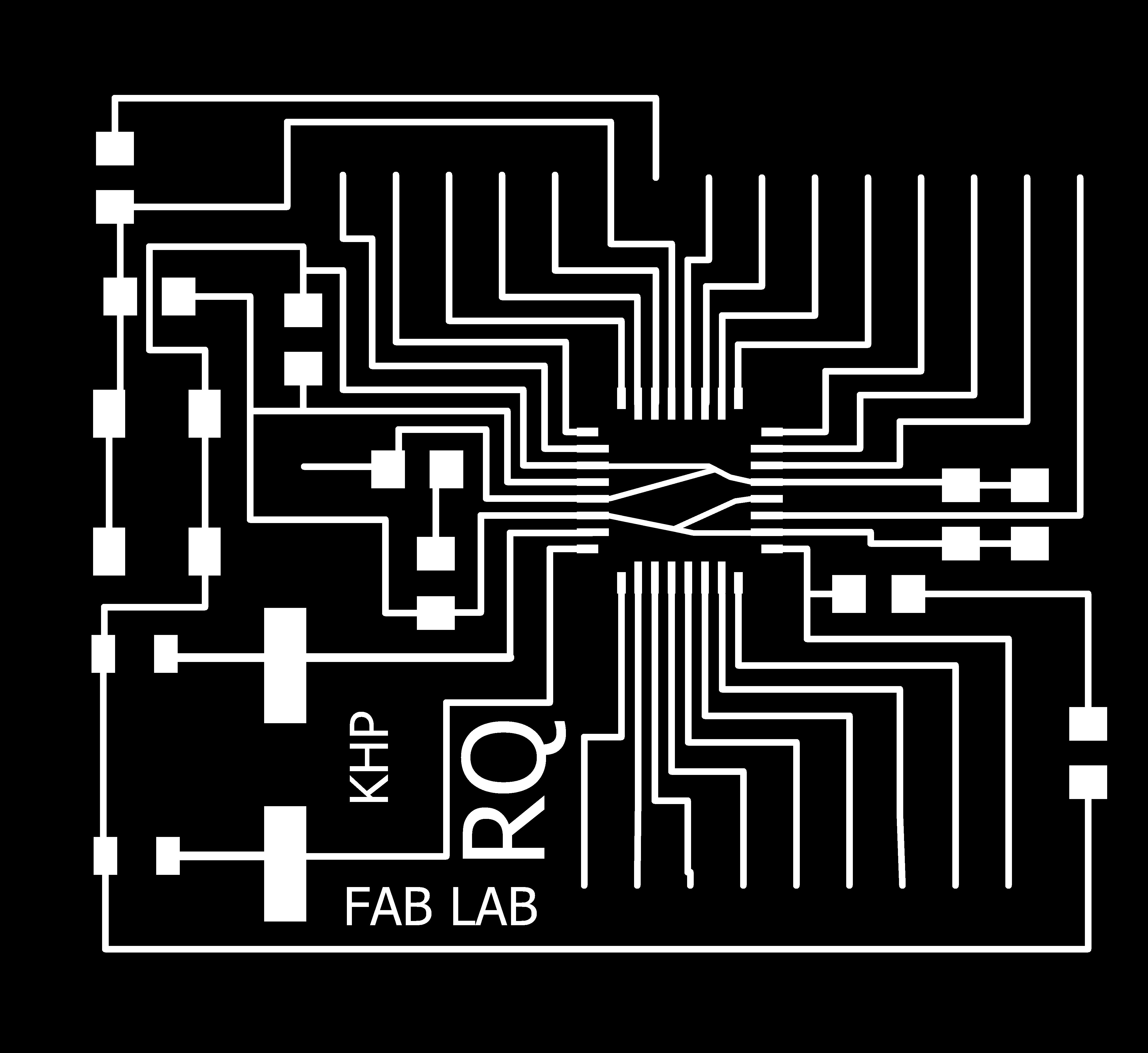
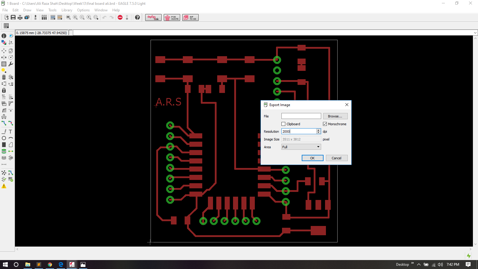
PCB Board
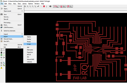
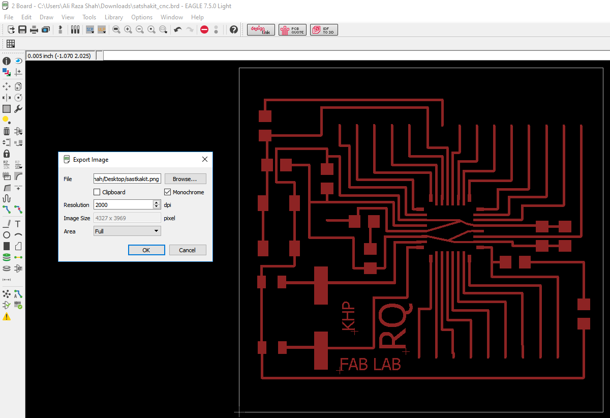
Export as Image
In the appearing window, I increase the resolution to 2000 dpi, click on monochrome, and click Ok.
Normal Seting
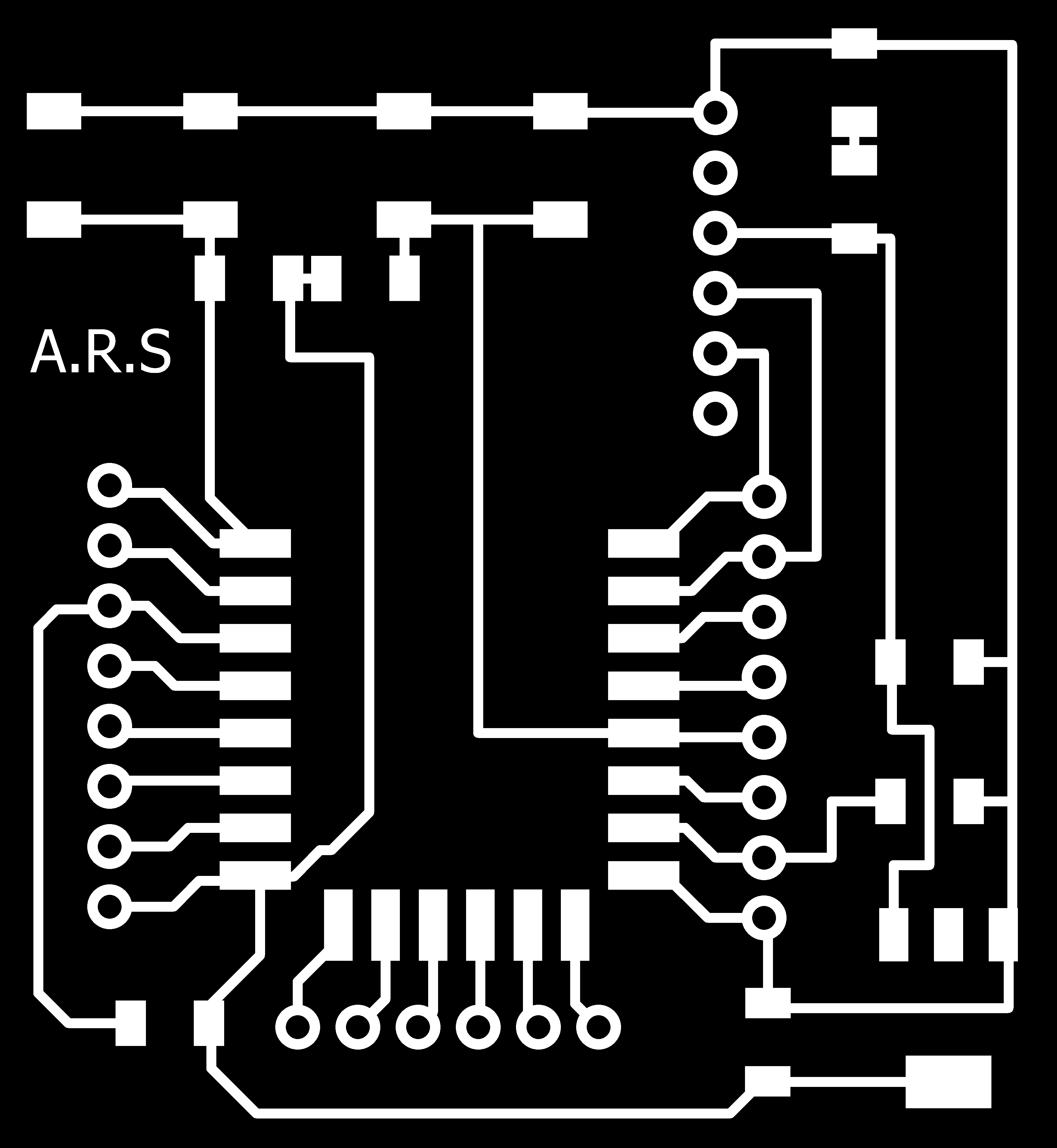
To edit the .png image, I Used Paint. I open my image in paint, and using the rectangular select tool, I select the image leaving some space from all the sides. After I press File and Copy the selected area. To continue working with the selected picture, I click again on File, and Create from the Clipboard
More detailed procedures can be found in my previous documentation Electronics Design week!
Trace

Outline
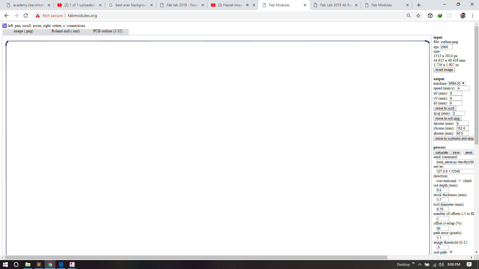
after making traces and outline of a pcb I used fabmodules to generate RML files of both traces and outline, all important settings are mentioned for detailed fabmodules settings visit Electronics Production Week

Components
Above list of components files i have generated from Eagle
.rml files are given to Roland SRM-20 for milling, 1/32 drill bit is used for cutting outlines and 1/64 bit drill is used to make a trace on a board and here is the result
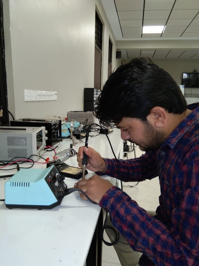
Soldering
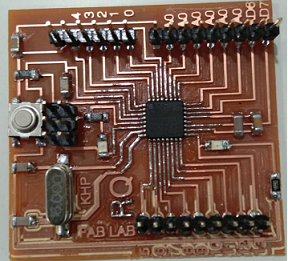
PCB
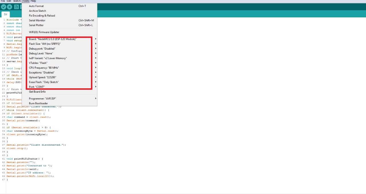
I am using Arduino IDE for programming my board. Before programming the board first it is required to burn bootloader in it. For setting up Arduino IDE to work with FabISP I mentioned in detail in Embedded Programming Week. I connect the arduino board to the USB. Under Tools select the right board, select Arduino as ISP USBtinyISP, double check the parameters, and press the Burn Bootloader button.:
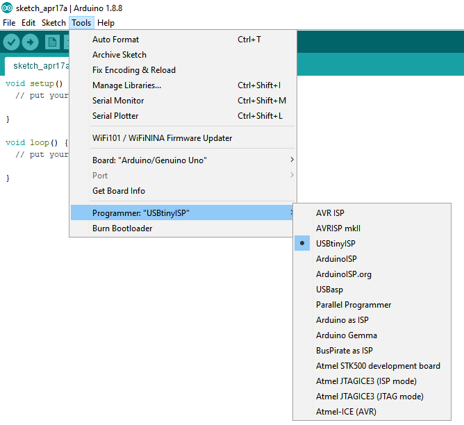
Programmer
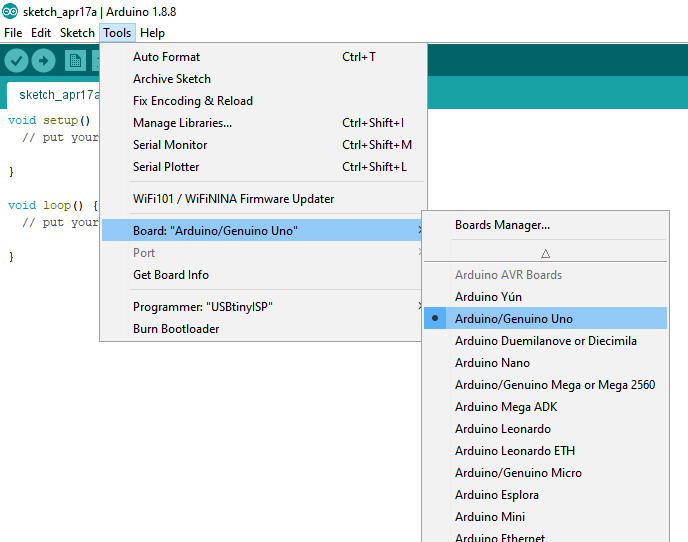
Selecting Board
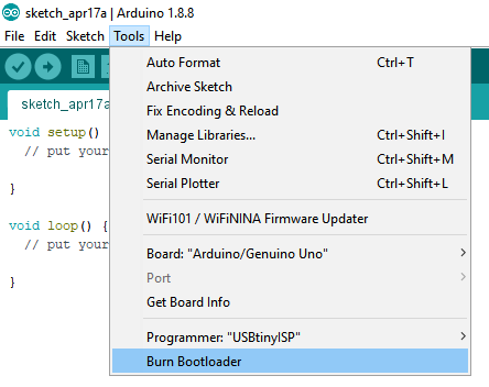
Burn Bootloader
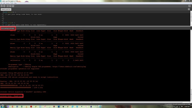
Done Burn Bootloader
After successfully upload and burn bootloader , now It is time to connect RGB strip WS2812B with board and program it to run differnet color effects
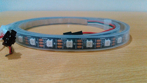
WS2812B RGB strip
Connect RBB strip address pin with Pin-6 of 328p board and connect supply pins VCC and Gnd with external source. I used five volatge adopter for external source
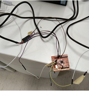
Connection
For RGB Led code I go to my local Instrcutor 2018 Student Noor Ahmed Pirwani webpage where he mention fastled library for RGB . I Used fastled Library for differnt patterns ,effects and upload it in my 328p board
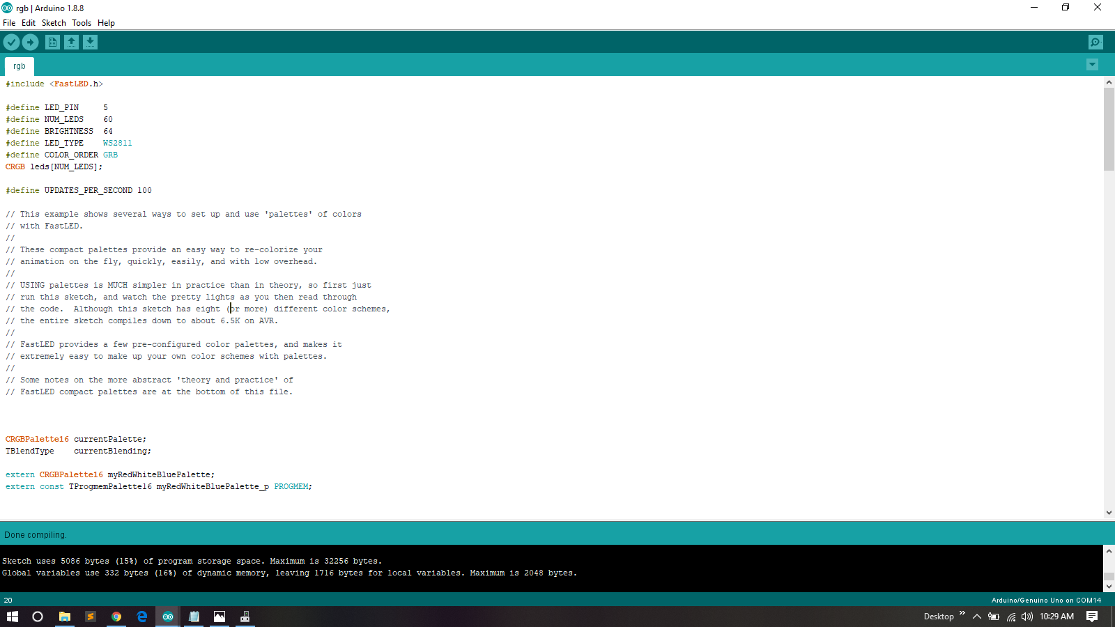
Program
Laser Cutting
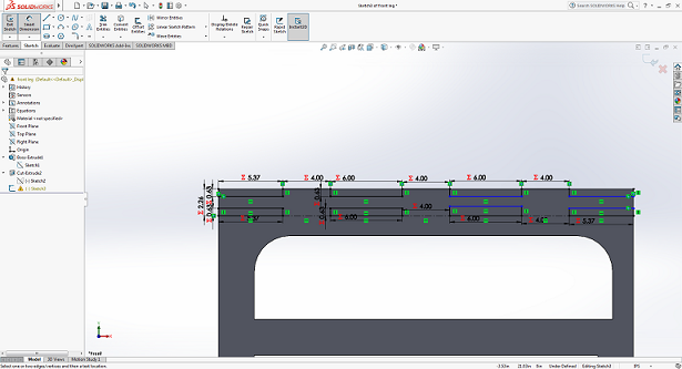
For final project one of te requiremet is it must be parametric and and cover many process and skills that we learn during fab acadmey.for including of laser cutting in one of the requirement for my final project is to desing frame for leds, Where I palced leds.So for this i decided to make it using laser cutt. So I start design of frame using solidworks.
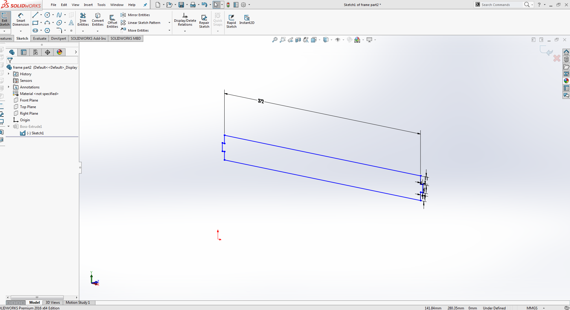
Side1
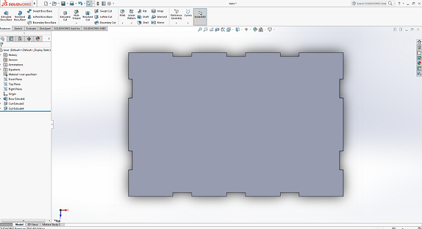
After designing this side the next step is to extrude the design.
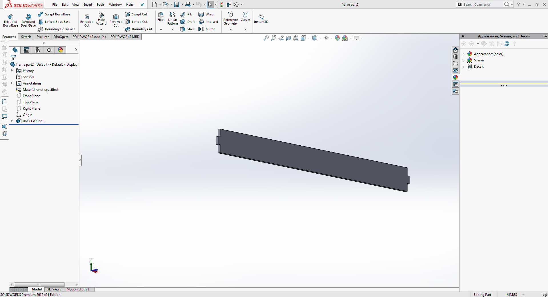
After extrude
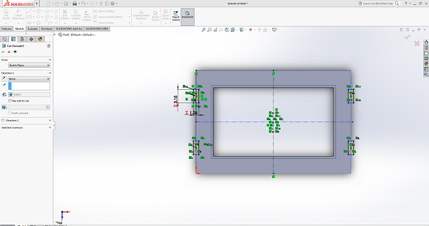
The next step for frame design is to design another side according to the requirements.For this side i decide to create whole in it for wiring of leds.So I start designing and sketch image is given below.
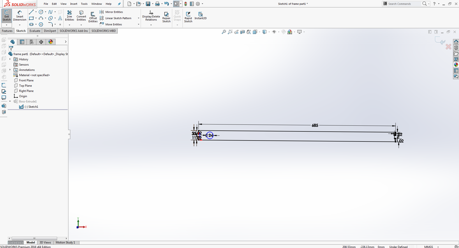
Creating Whole
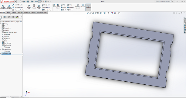
Again same process of extrude cutt.After extrudion the design looks like this
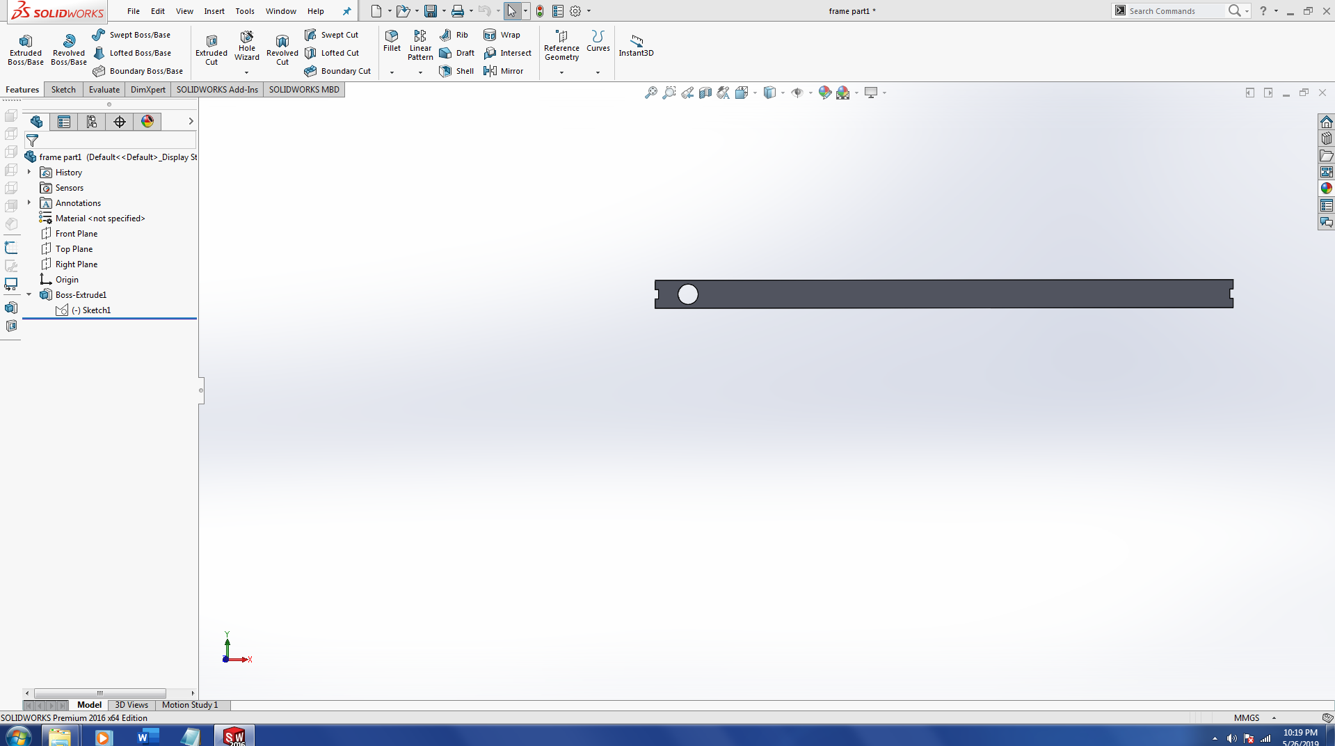
After extrude
After designing file in solidworks the next step I perform is save file as dxf.
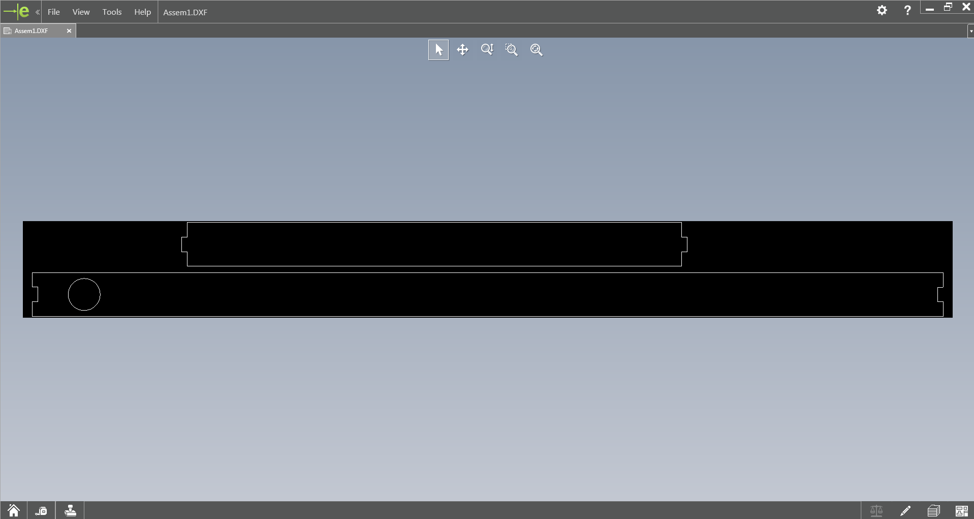
Dxf
In order to generate file for laser cutt machine we need to follow some steps for setting file and save as pdf format.So for this I import file in inkscape and make some changes like fill stroke to 0.001, and document property to ARC-E
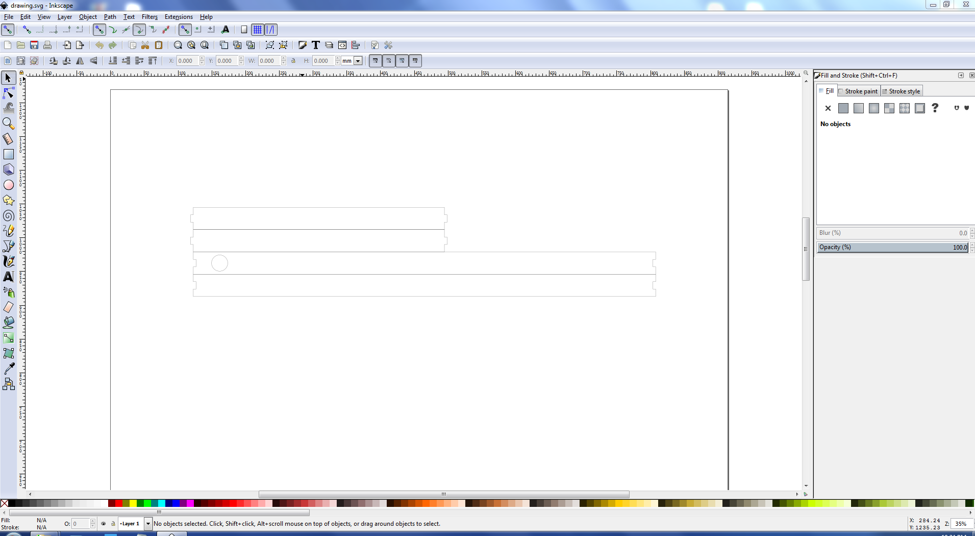
Open In Inkscape
I grouped all files and move them accordignly and save file as pdf . And file Is ready for laser cutting.
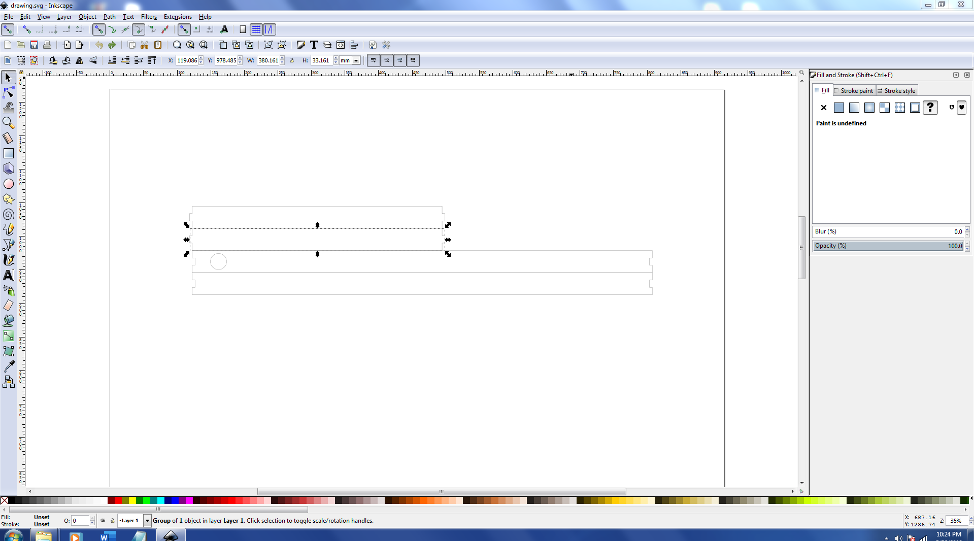
Inkscape
After applying setting in epliog I send the job to the laser cutting machine and it recieve with name ali1.
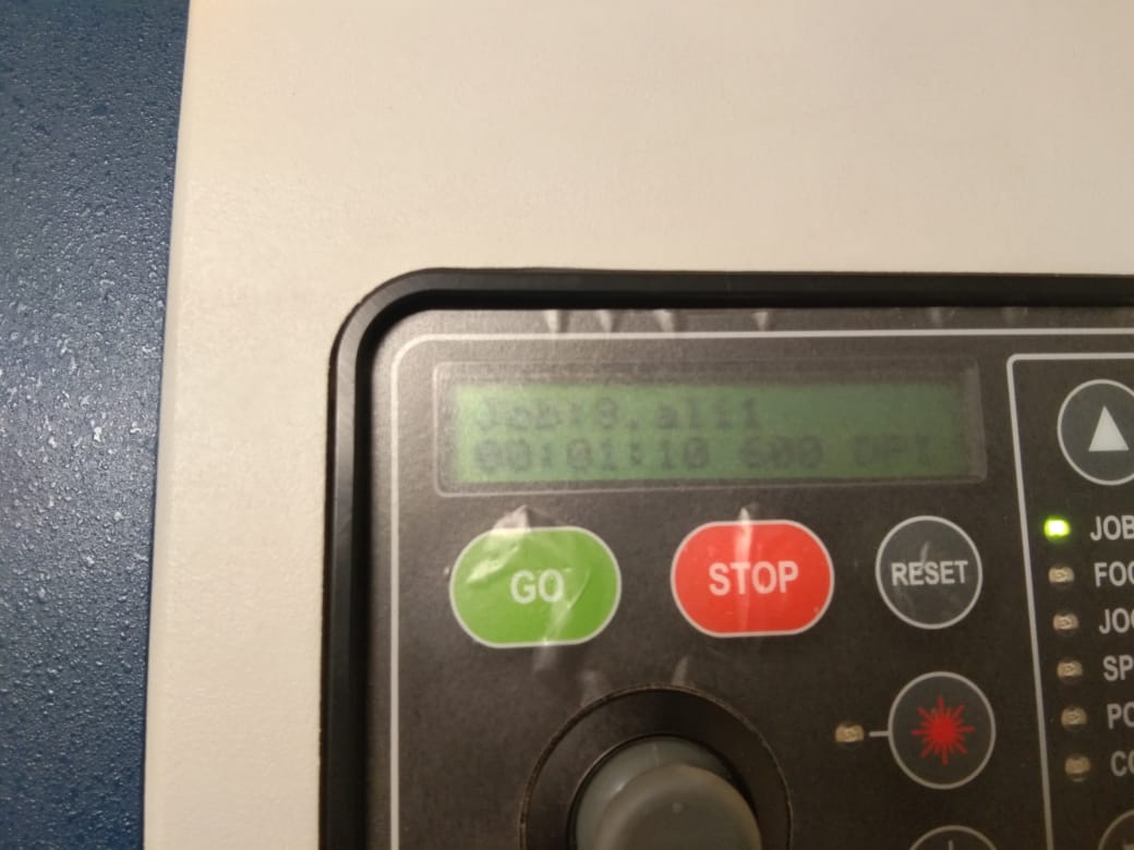
JOB Recieved!
Finaly machine start .
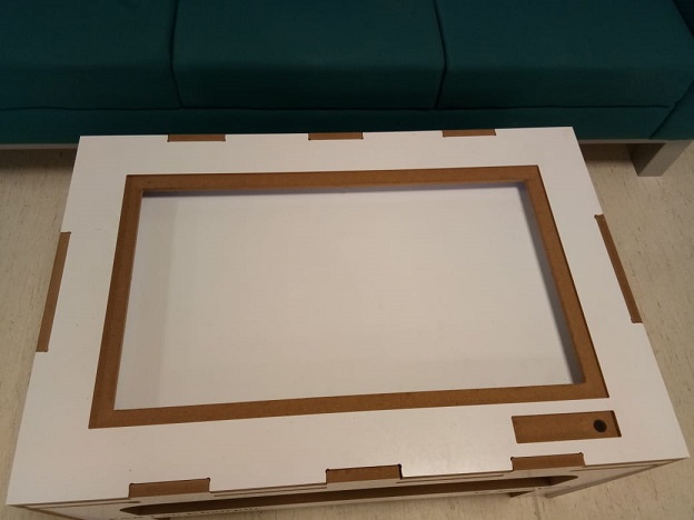
After machine finishing his job the next step is to assemble the part.
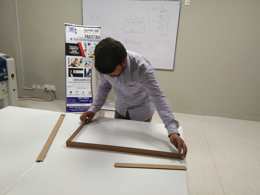
While Assembly
After Assembling the frame looks like this.
Frame
Now it's time to insall leds in frame. I used led strips and making connection for leds. As I Mention earlier that I created whole for leds connection from that whole I cross wires and easily make connection with main board.
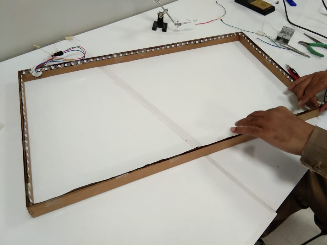
LEDs
For testig purpose I give 5 volt power to leds and after that the frame looks like this.
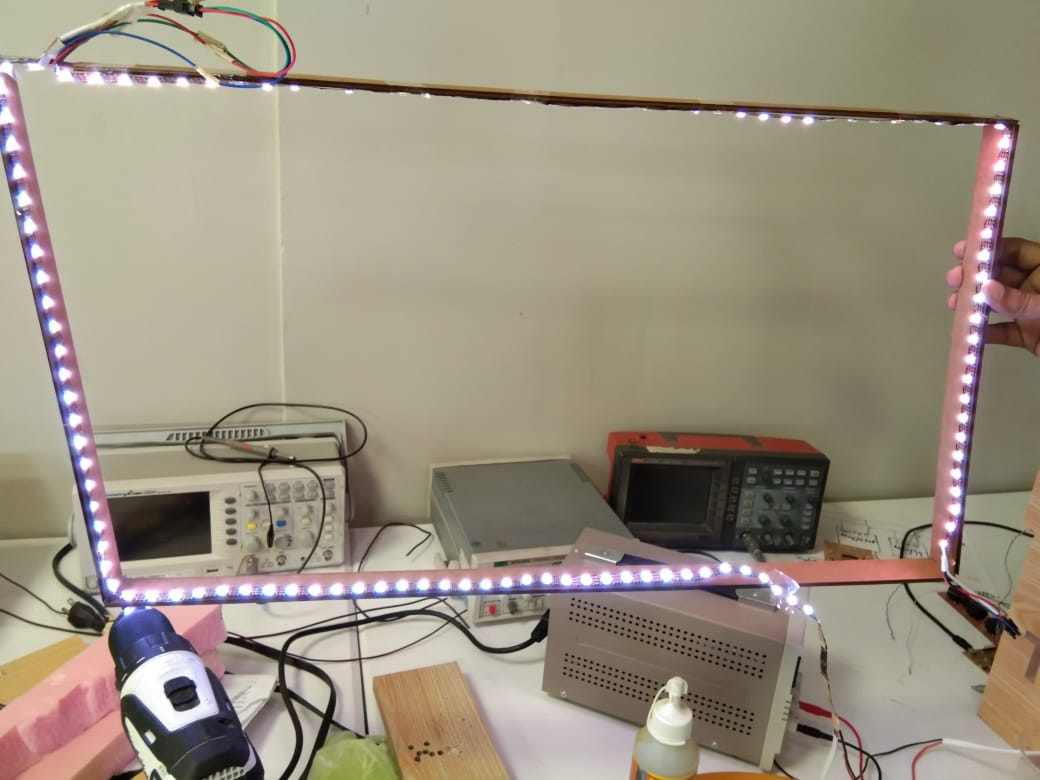
LEDs
After that I also tried to program leds with differnt colors here is one of the example.
3d Printed Buttons
For 3d printed buttons and body for buttons Initillay I measure the size of the board ,width and size of the push buttons.Here i sthe image of the button board that I have dsigned for my final project.
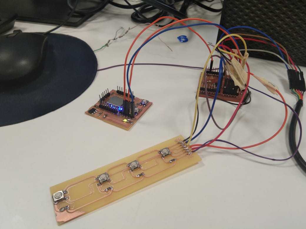
buttons Board
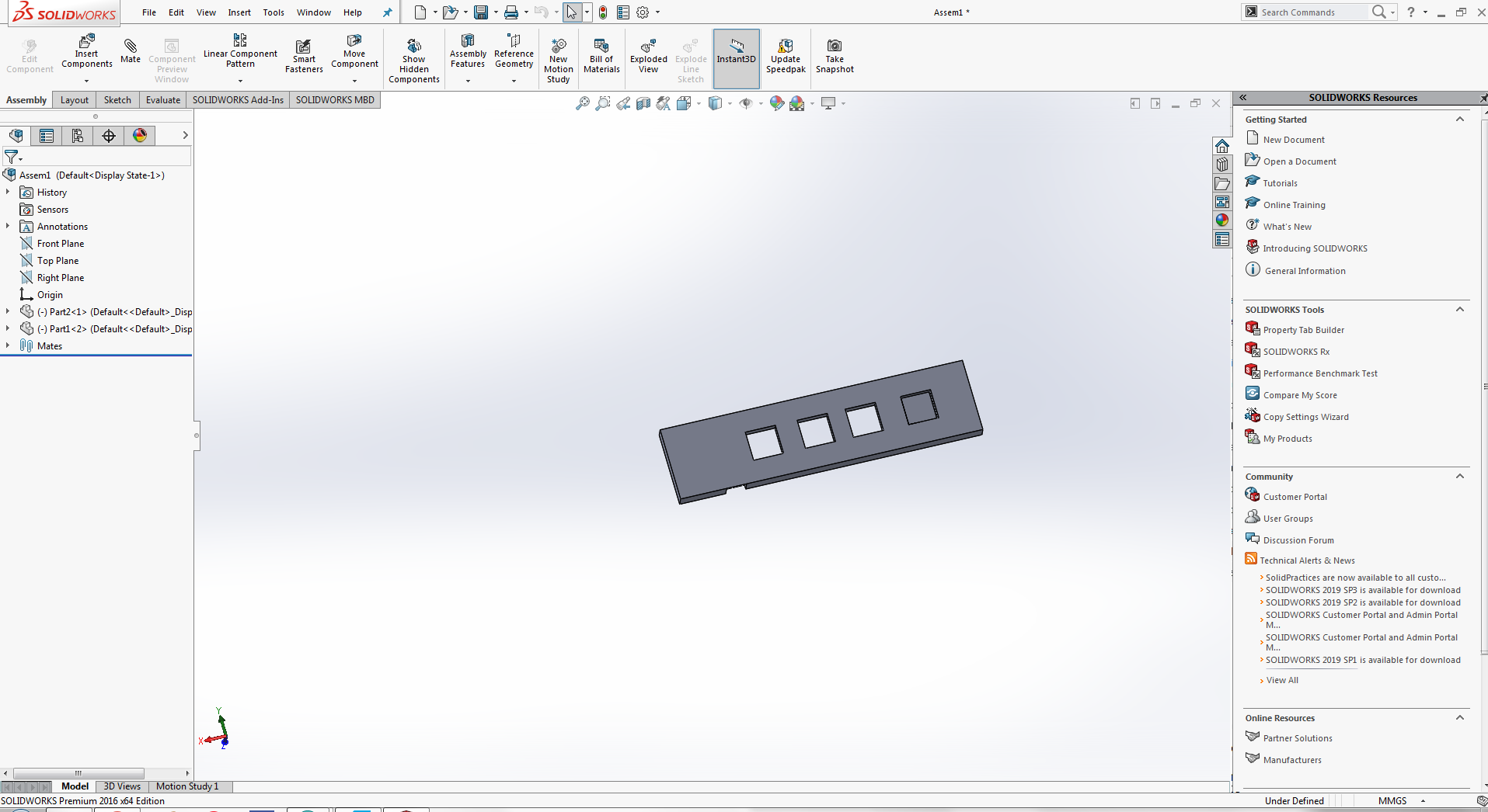
After measuring each and everything I start design button in solidworks. initillay I just design one button for test purpose to check weather the buttons are pressed easily or not. So I started Designing in solidworks.
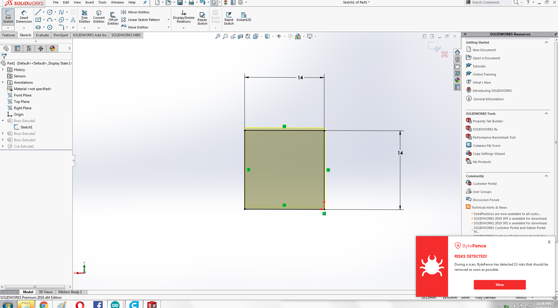
Define Dimensions
Define Dimensions
Outer Dimension
After extrude cut The button looks like this
After Extrude
The back side of the button
Back Side
After dsigning button I start Designing body for the buttons, The size of the body is actullay the size of the board buttons that I have designed.
Body
I add another sketch on the body and designed inner part of the buttons on it.
Body
After extrude I measured the size of the inner part of the button and comapre with the actual size f the button so they can easily fit and buttons can be pressed easily.
Measuring
Here is The image of the body After extrude cut
After Extrude
After designing both parts I open both files in assembly part and asemble them.
Assembly
Now It's time to print design on 3d printer, Before that we need to perform some steps to perpare file for 3d printer.
Here are the some steps that i follwed for perparing file for 3d printer.
Initially I generated file as stl from solidworks then I import taht STl file in cura software for perpare file for 3d printer.
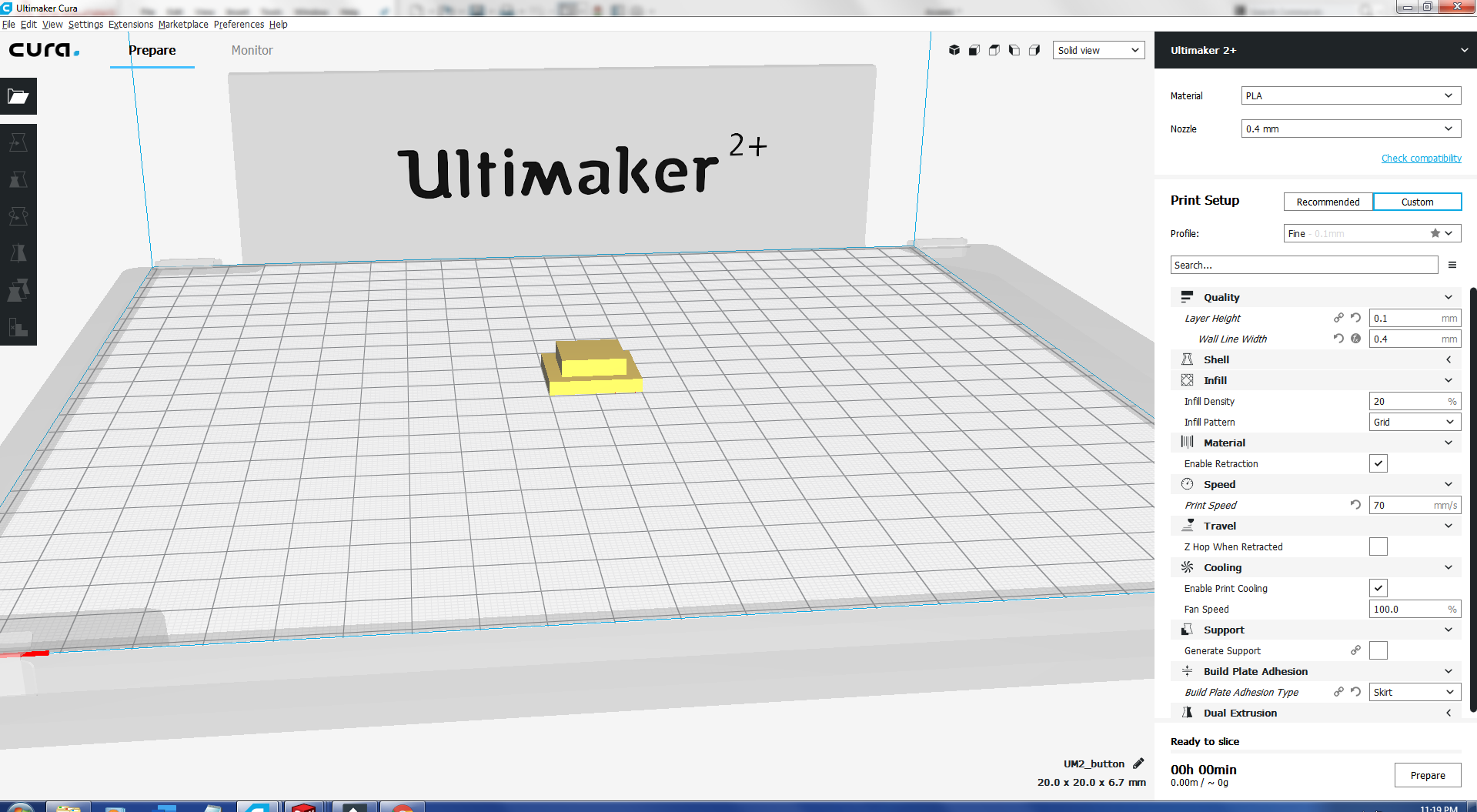
Cura
I Setting cura file according to the Extend+2 printer that i savailable in our lab.
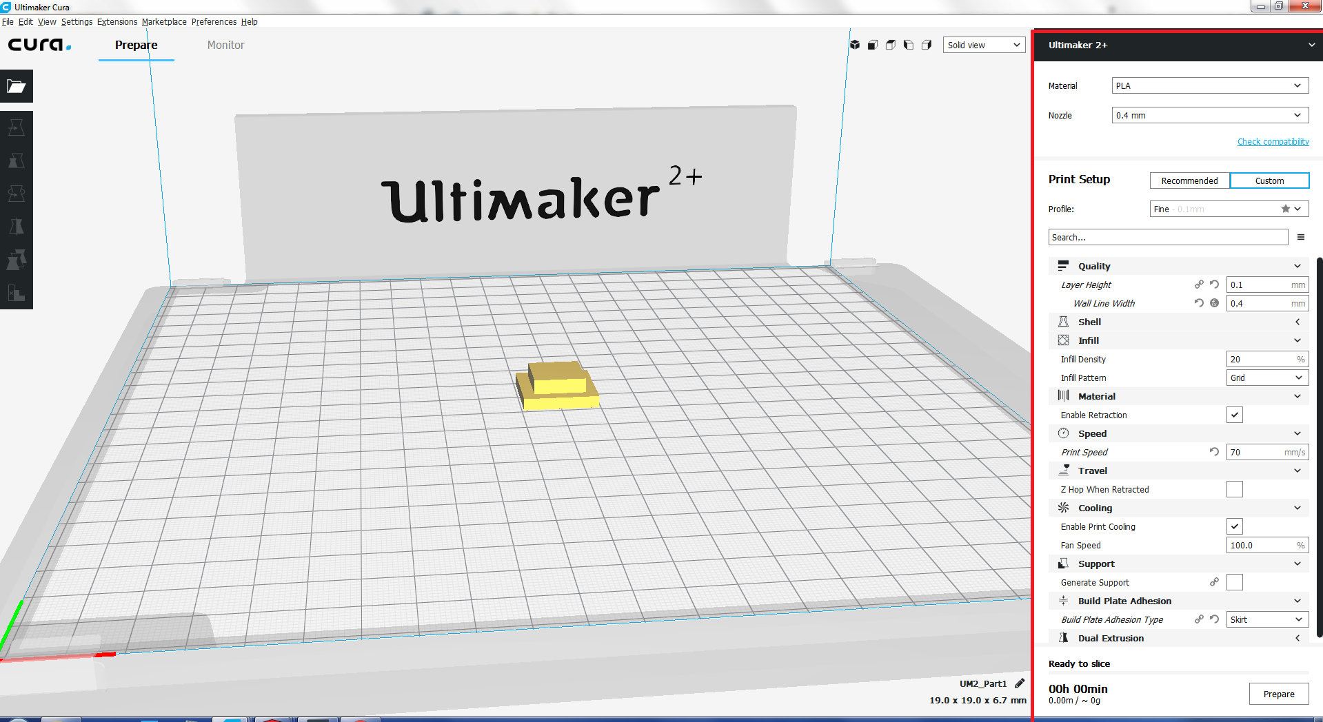
Setting
I printed three color buttons two of blue and one is red and white rspectively. Here is the video of 3d printed button during printing.
After printing one button I printed body of the board.
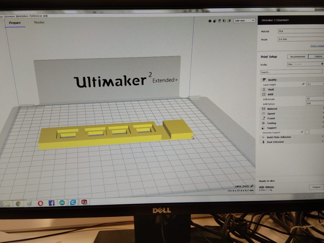
body
I decide to add one button and print simultanously because this time Iam going to print blue color button. Here is the another video during printing
After printing I tested the button when I pressed buttons it looks fine 😜
After testing I fixed that in my table and assign name to the buttons .
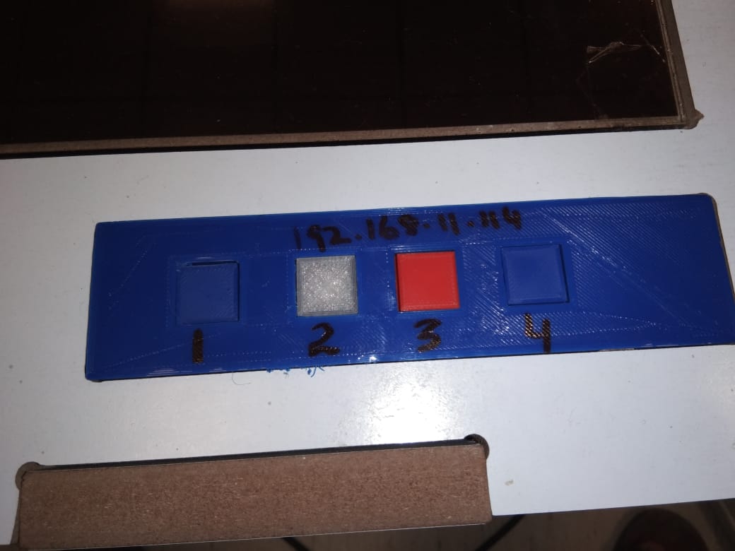
Buttons
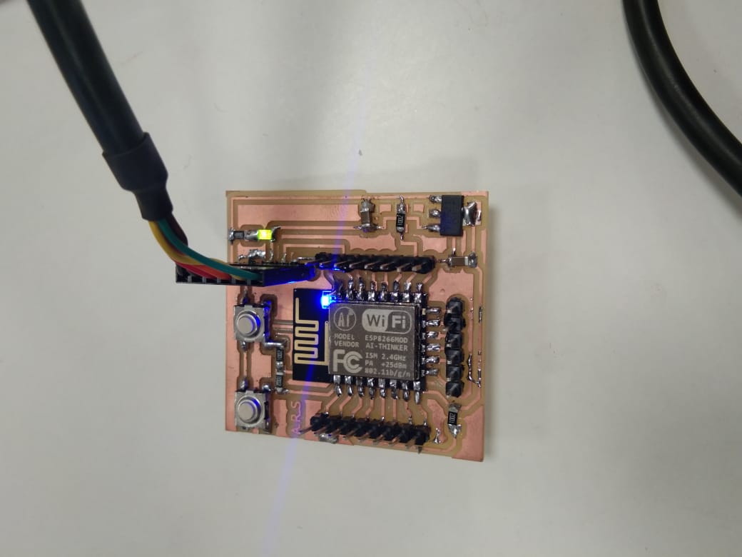
ESP-12E is a miniature Wi-Fi module present in the market and is used for establishing a wireless network connection for microcontroller or processor.
The core of ESP-12E is ESP8266EX, which is a high integration wireless SoC (System on Chip). It features ability to embed Wi-Fi capabilities to systems or
to function as a standalone application. It is a low cost solution for developing IoT applications.Source
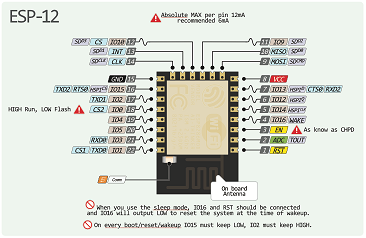
ESP-12E Pin Description
For PCB designing I worked on Eagle 7.5 First I made a schematic of board:
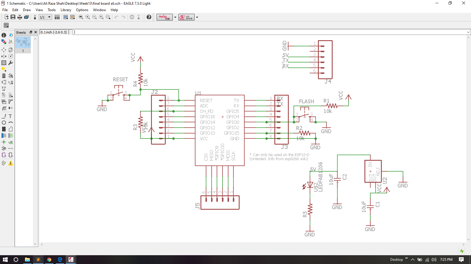
ESP-12E Board Schematic
After Schmatic I generate PCB board and route it.
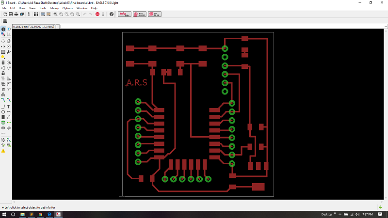
ESP-12E Board
For generating RML files, first I need my PCB design in .png format for that I export my PCB design in .png while setting up 2000 dpi and Monochrome
Exporting PCB design into .png format
.png is processed in Paint for making seperate files for traces, outline and drill holes of a PCB design
PCB Trace

PCB outline

Holes
After making traces, outline and drill holes of pcb I used fabmodules to generate RML files of both traces and outline, all important settings are mentioned in a pictures below, for detailed fabmodules settings visit Electronics Production Week
Generating .rml file of PCB traces
Generating .rml file of PCB outline
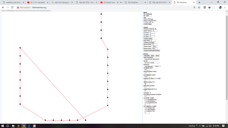
Generating .rml file of PCB drill Holes
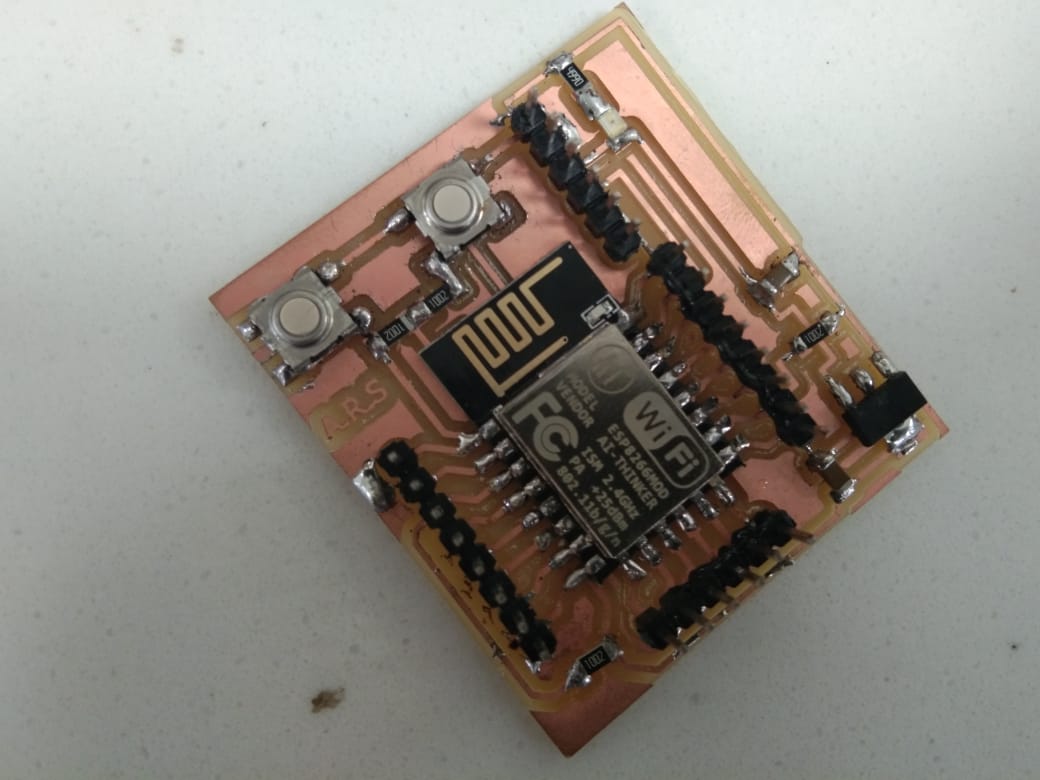
.rml files are given to Roland SRM-20 for milling, 1/32 drill bit is used for cutting outlines and for drill holes, and 1/64 bit drill is used to make a trace on a board and here is the result.
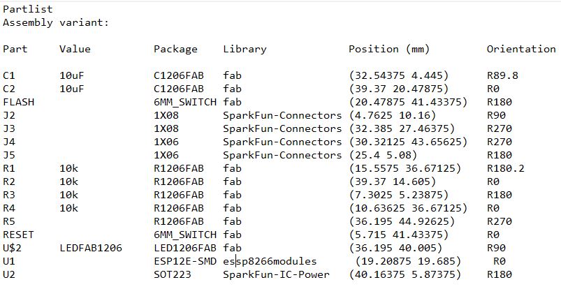
List Of Compoents
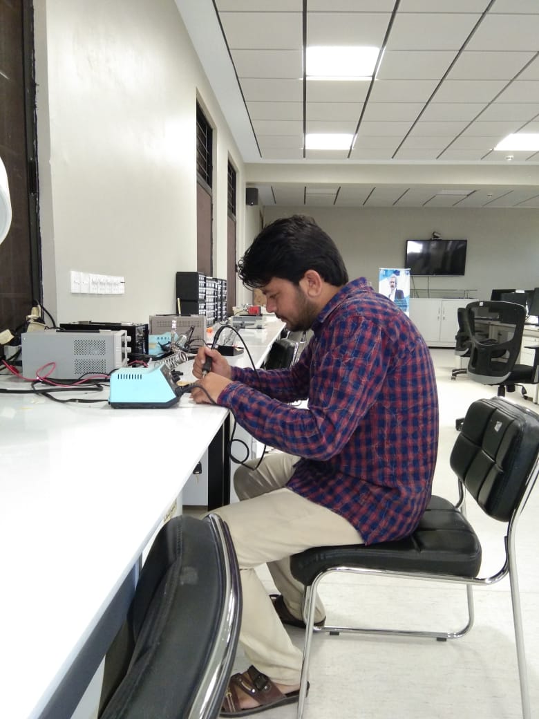
Soldering
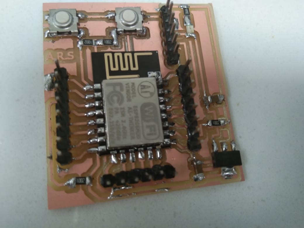
Soldered and ready to burn board
After soldering the next step is programming the board .I configure esp8266 tcp server, and download Tcp Telenet Terminal Mobile application from Playstore.
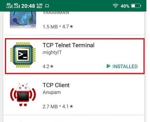
Download and Install TCP Client
After Downloading TCP client I programmed My Esp8266 in such way that it work like Access point or TCP server, and tcp client get IP Address that is offered by TCP server and make connection with server and start two way communication with each other.
\Initially I faced error realted to wifi library.I did not add Wifi library and continue uploading code. 😜
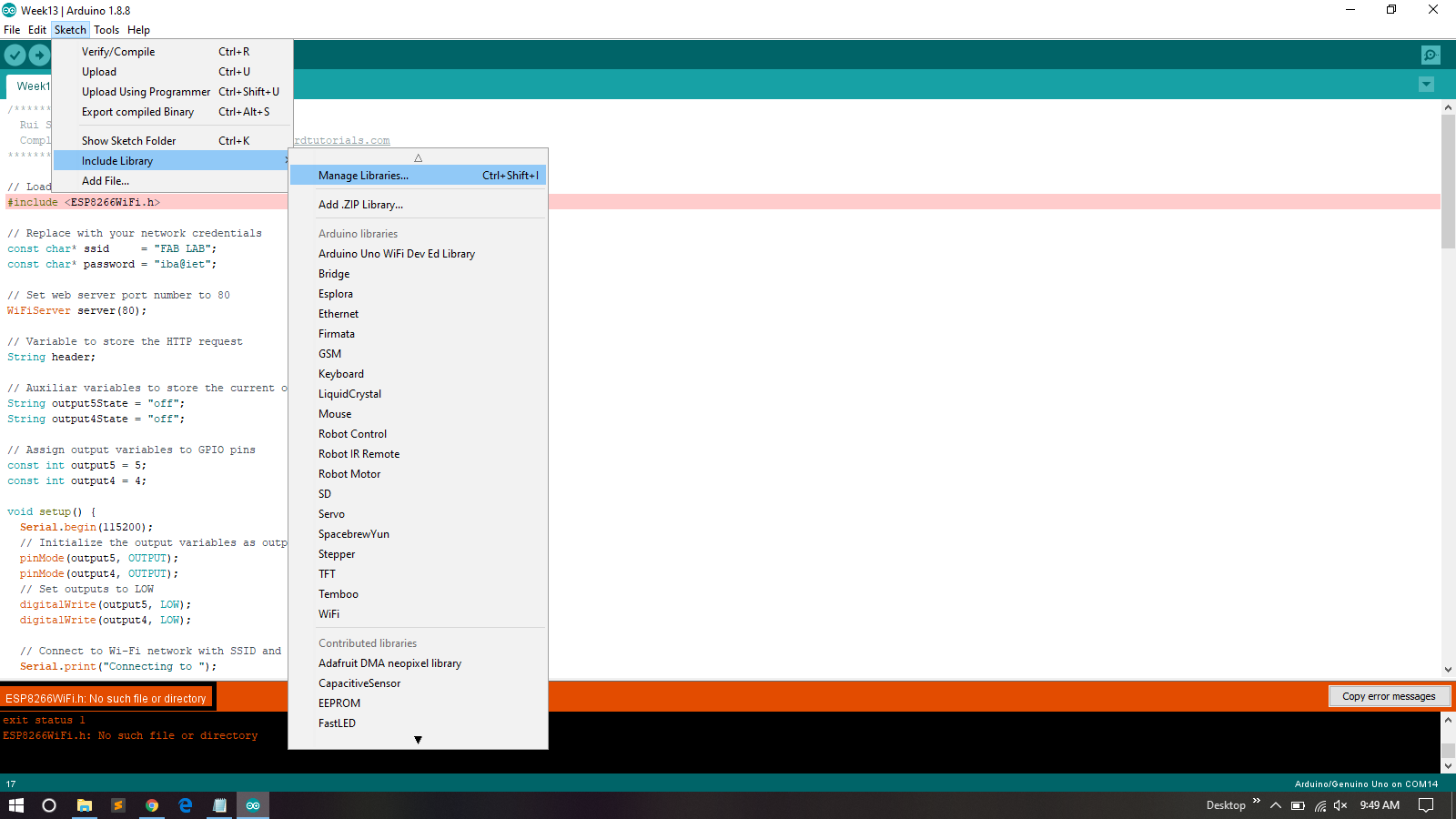
Library Error
After That I add Wifi Libray
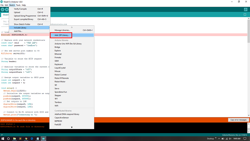
Add Zip File
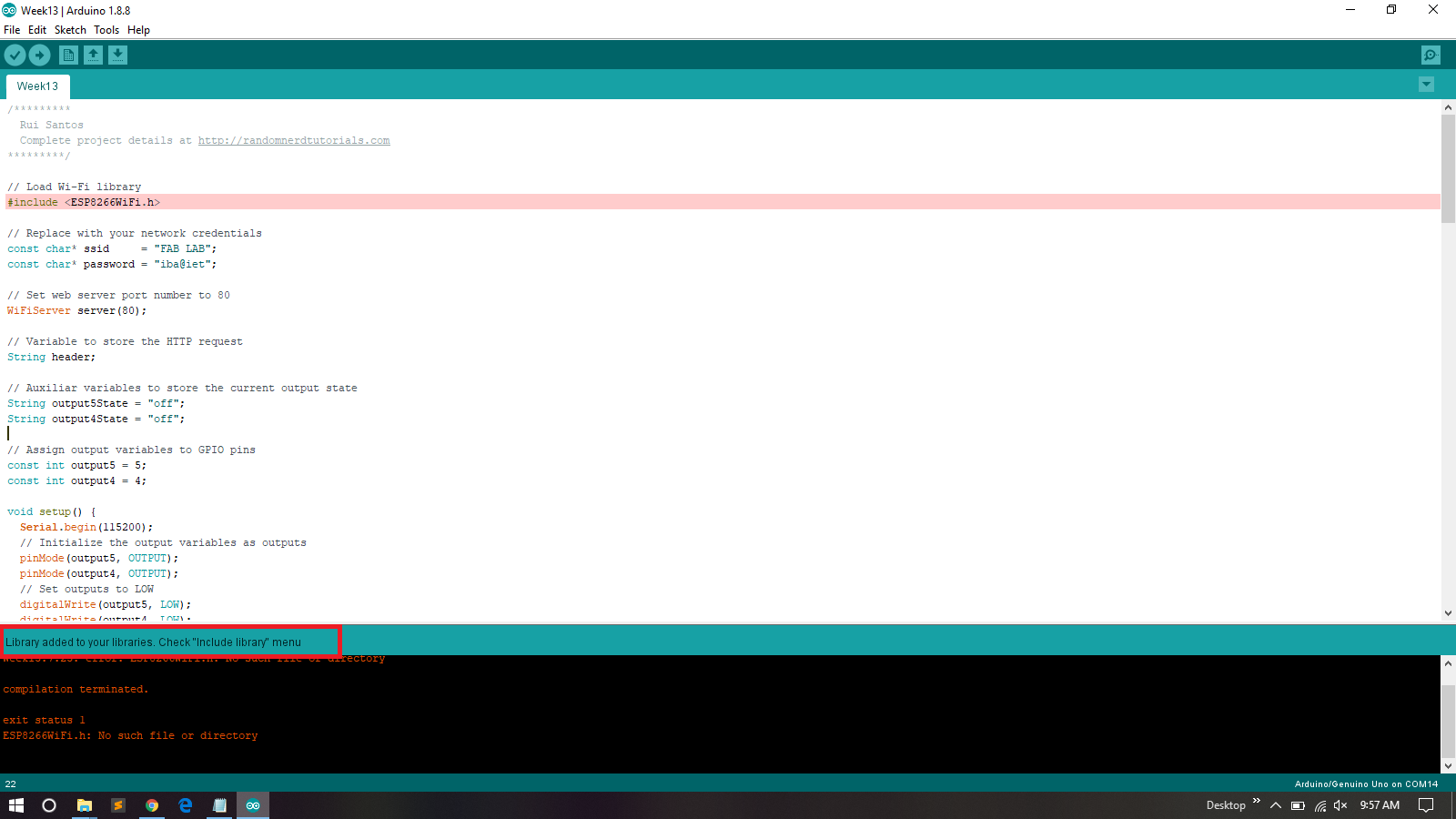
Included
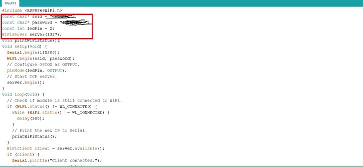
Set SSID , Password and PORT Number
I Define my SSID , pasword and pot Number of the local aera network , and client must be connected to same network if client connected with other network then communication between Server and client is not possible.
For this assignment I want to write an application in java which can send and receive data from a given IP as TCP client and will make its GUI using Andorid Studio. I made Esp-12E board in Networking and communication week so for this week Iam also interface that board with my Mobile application.
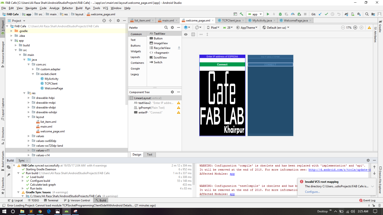
As I mentioned earlier that for this week Assignment Iam going to design mobile App, For App devolpment I used Andorid Studio.
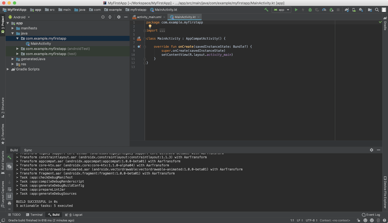
Android Studio is the official Integrated Development Environment (IDE) for Android app development, based on IntelliJ IDEA . On top of IntelliJ's powerful code editor and developer tools, Android Studio offers even more features that enhance your productivity when building Android apps, such as: A flexible Gradle-based build system A fast and feature-rich emulator A unified environment where you can develop for all Android devices Instant Run to push changes to your running app without building a new APK Code templates and GitHub integration to help you build common app features and import sample code Extensive testing tools and frameworks Lint tools to catch performance, usability, version compatibility, and other problems C++ and NDK support Built-in support for Google Cloud Platform, making it easy to integrate Google Cloud Messaging and App Engine Source
The Android Studio main window is made up of several logical areas
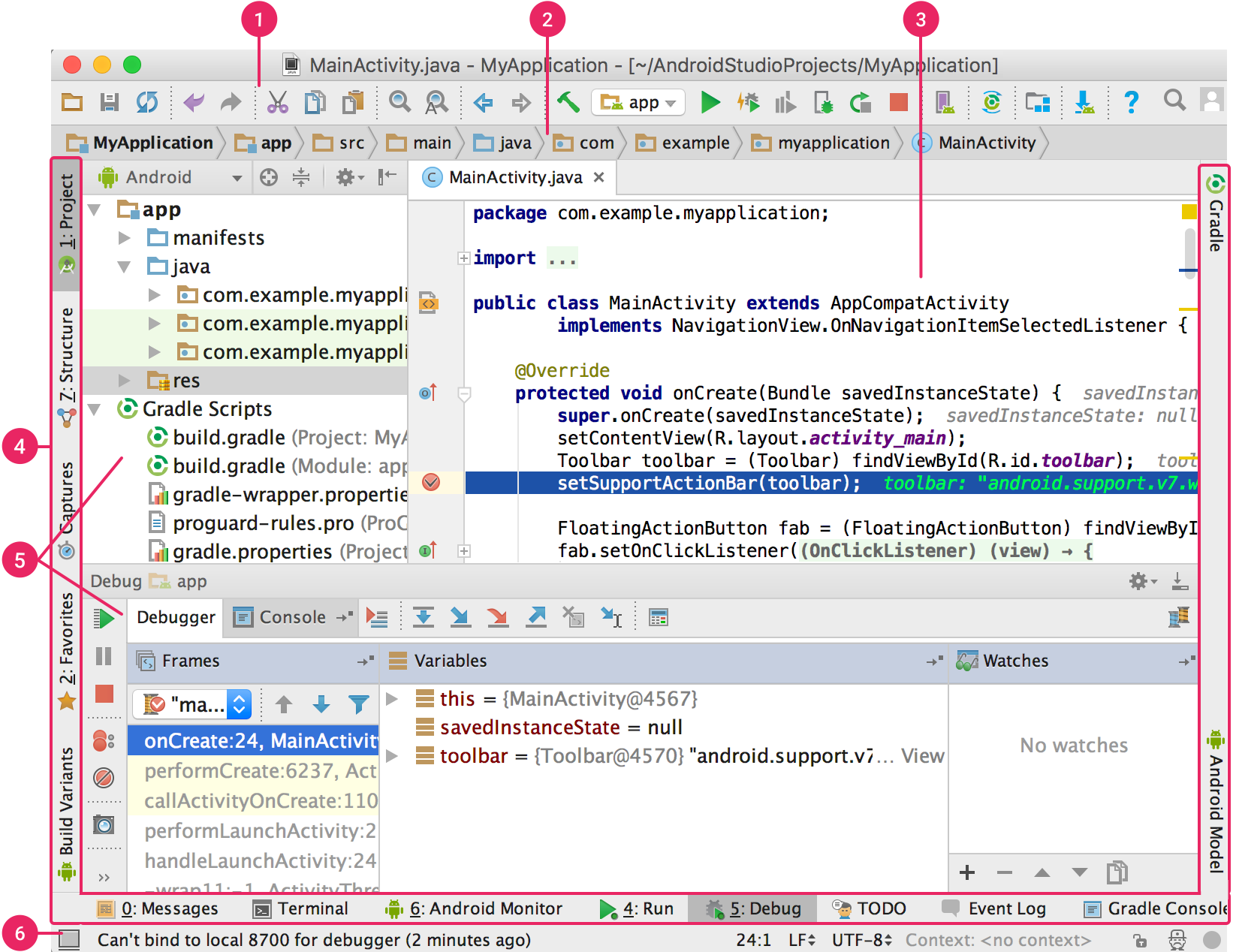
User Interface Of Andorid Studio
For Runing Andorid Studio you need to downald and install jdk and and set path. You may Download Java Devolpment kit from Here
After Downloading and installation of Jdk the next step is to download andorid Studio.For downloading andorid studio you may click Here
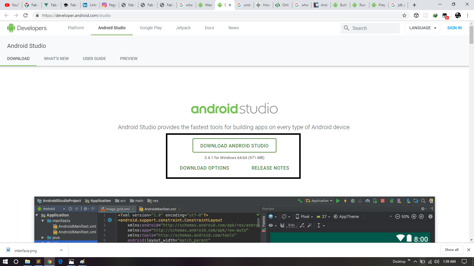
Downloading Andorid Studio
For Complete Process for Installation Process You May Follow this helpful Tutorial
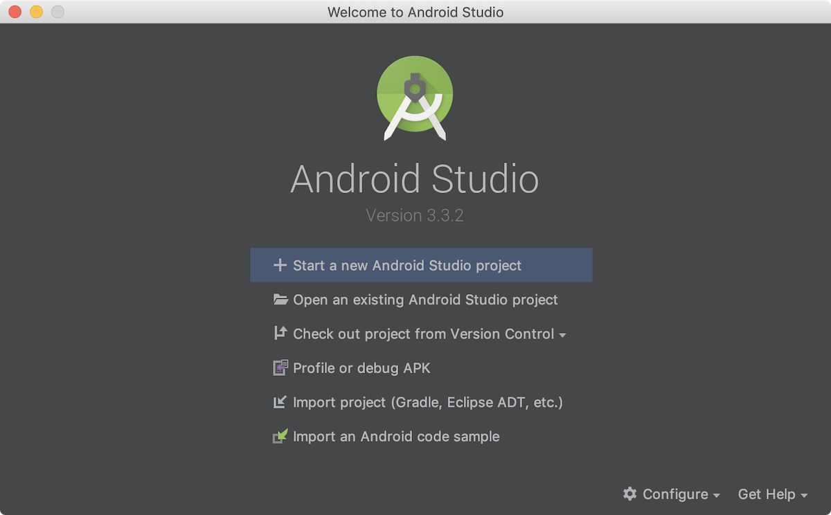
Start New Project
Or if you have a project opened, select File > New > New Project.
In the Choose your project window, select Empty Activity
Click Next.
In the Configure your project window, enter the following values:
Name: "My First App"
Package name: "com.example.myfirstapp"
Check the box next to Use AndroidX artifacts
You might want to change the project location.
Leave the other options as they are.
If you prefer to write your app in Java, select Java from the Language drop down.
Click Finish.
After some processing, Android Studio opens the IDE.
initially when we open IDE it takes time to open.
After processing
After opening
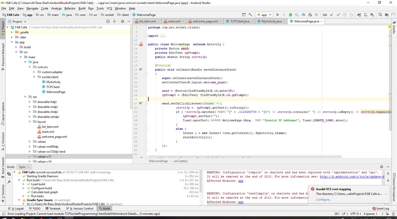
Fab Cafe Welcome page

Fab Cafe My Activity Page
You can run an app from an Android Studio project, or you can run an app that's been installed on the Android Emulator as you would run any app on a device.
To start the Android Emulator and run an app in your project:
Open an Android Studio project and click Run .
The Select Deployment Target dialog appears.
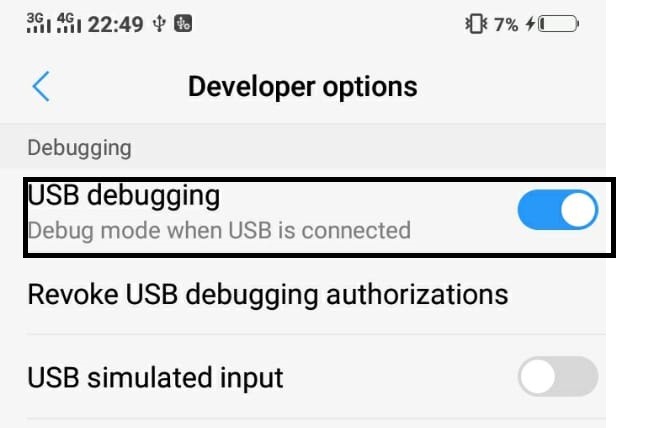
USB Debuging Mode
Before Run the appliction you need to On Debuging from device in which you are want to build application.For that you need to Go to the Setting and then you have to ON Devolper Options , then Go to the USB Debuging Option and ON it.
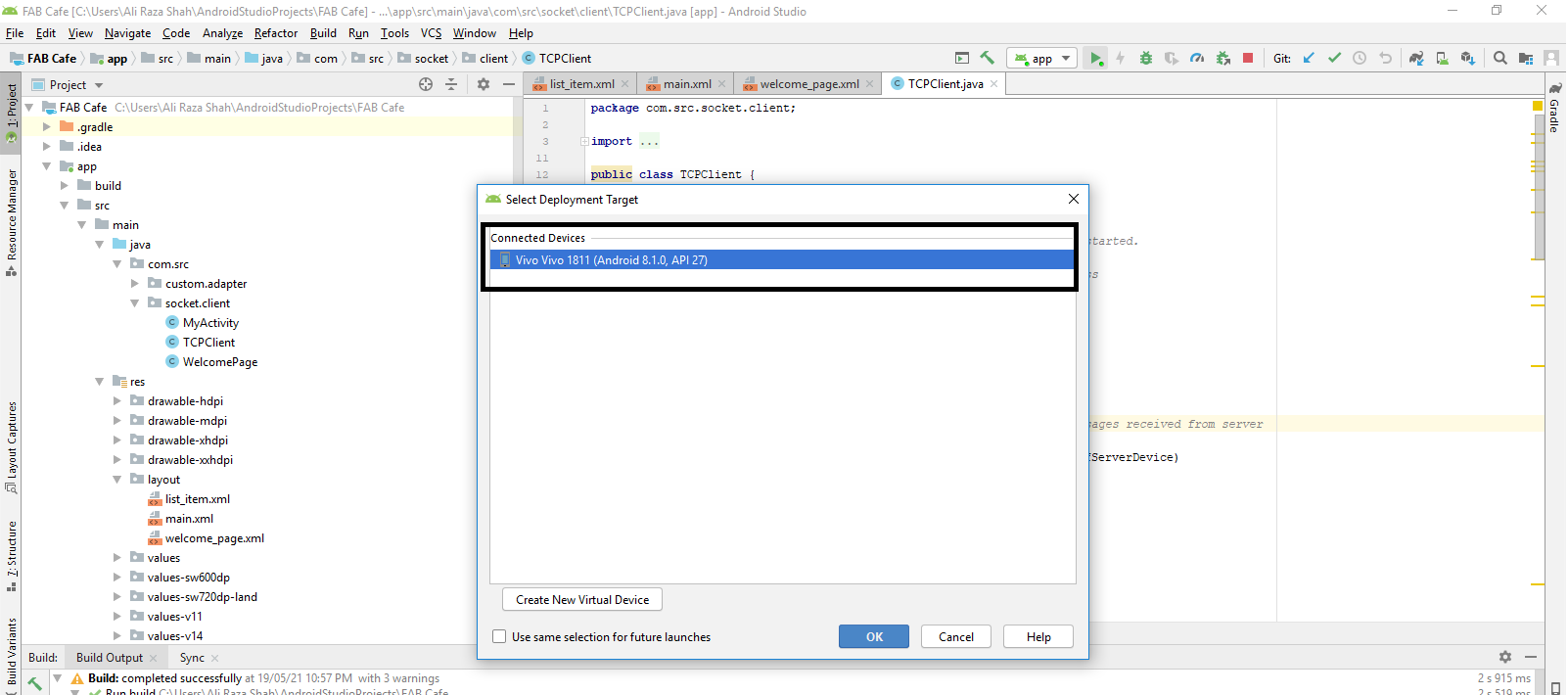
Selecting Device
Mobile Model
For Logo Design I take one cup of cofee from Google and edit it according to the requirement.I used Microsoft Powerpoint and paint for designing logo.
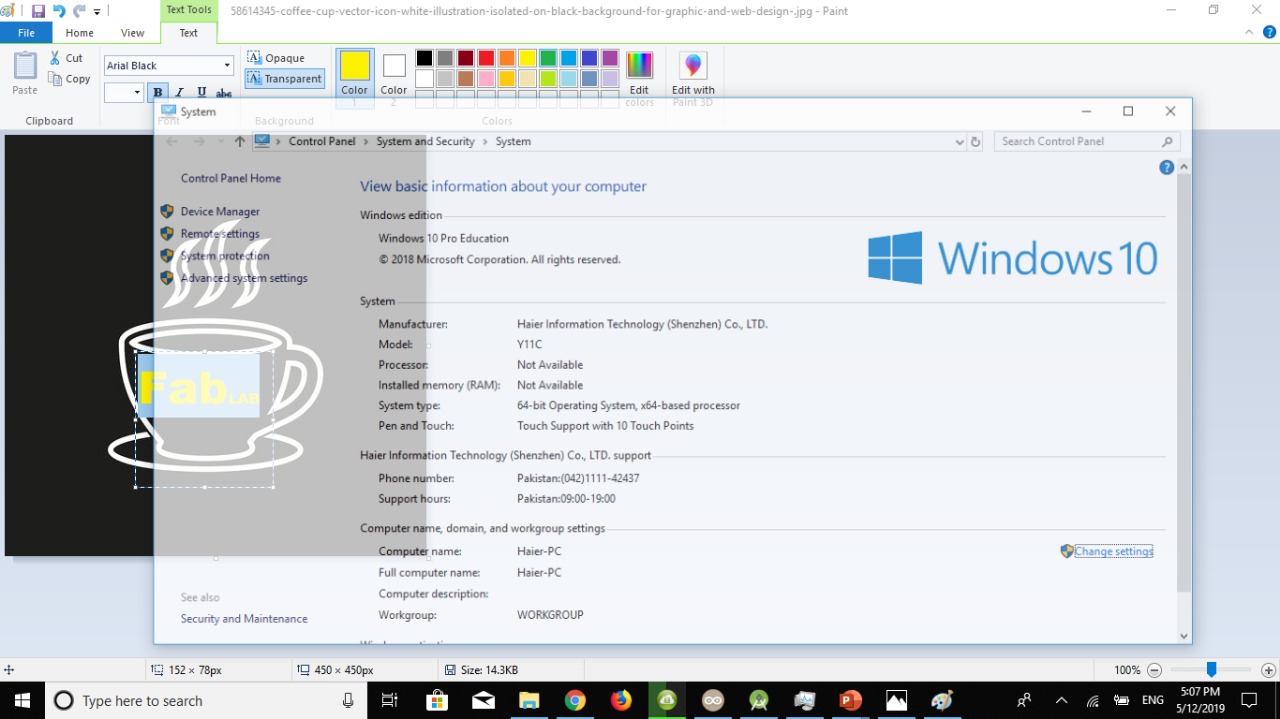
Paint
Initially I opend this picture in paint and write text on it.I tried differnt text colors for logo finaly I go for yellow .
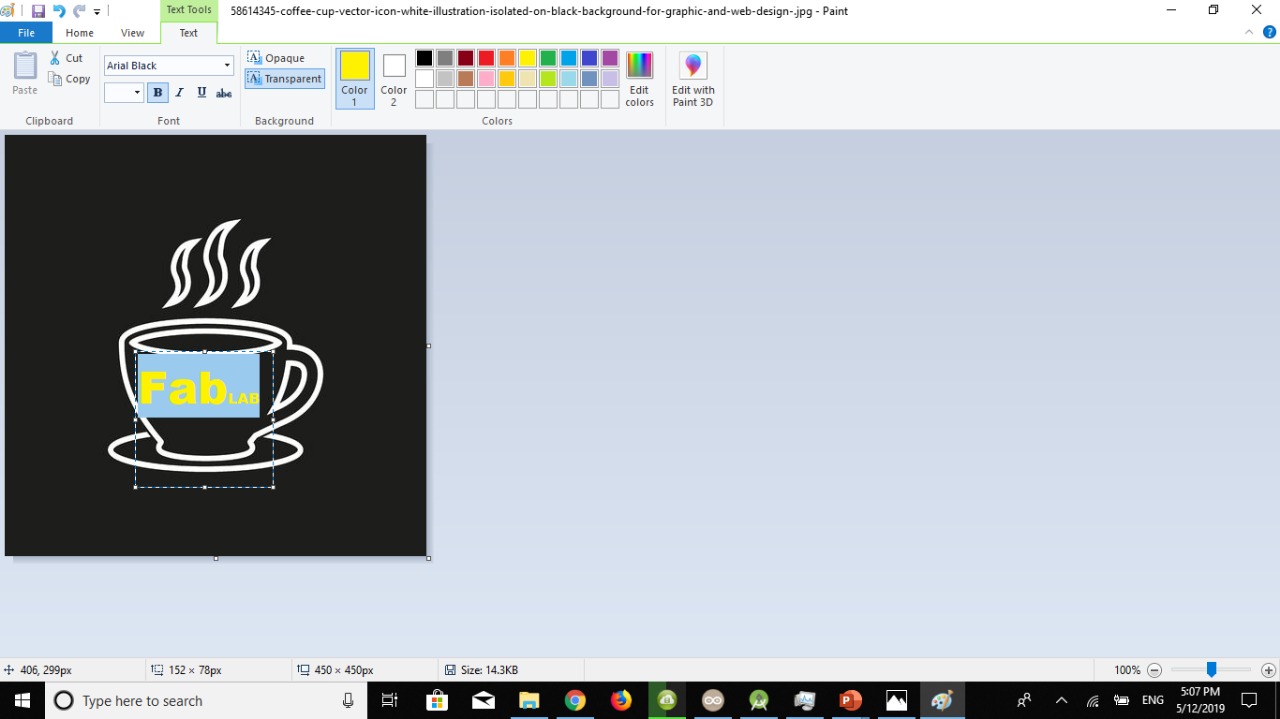
Microsoft Paint
Microsoft Paint
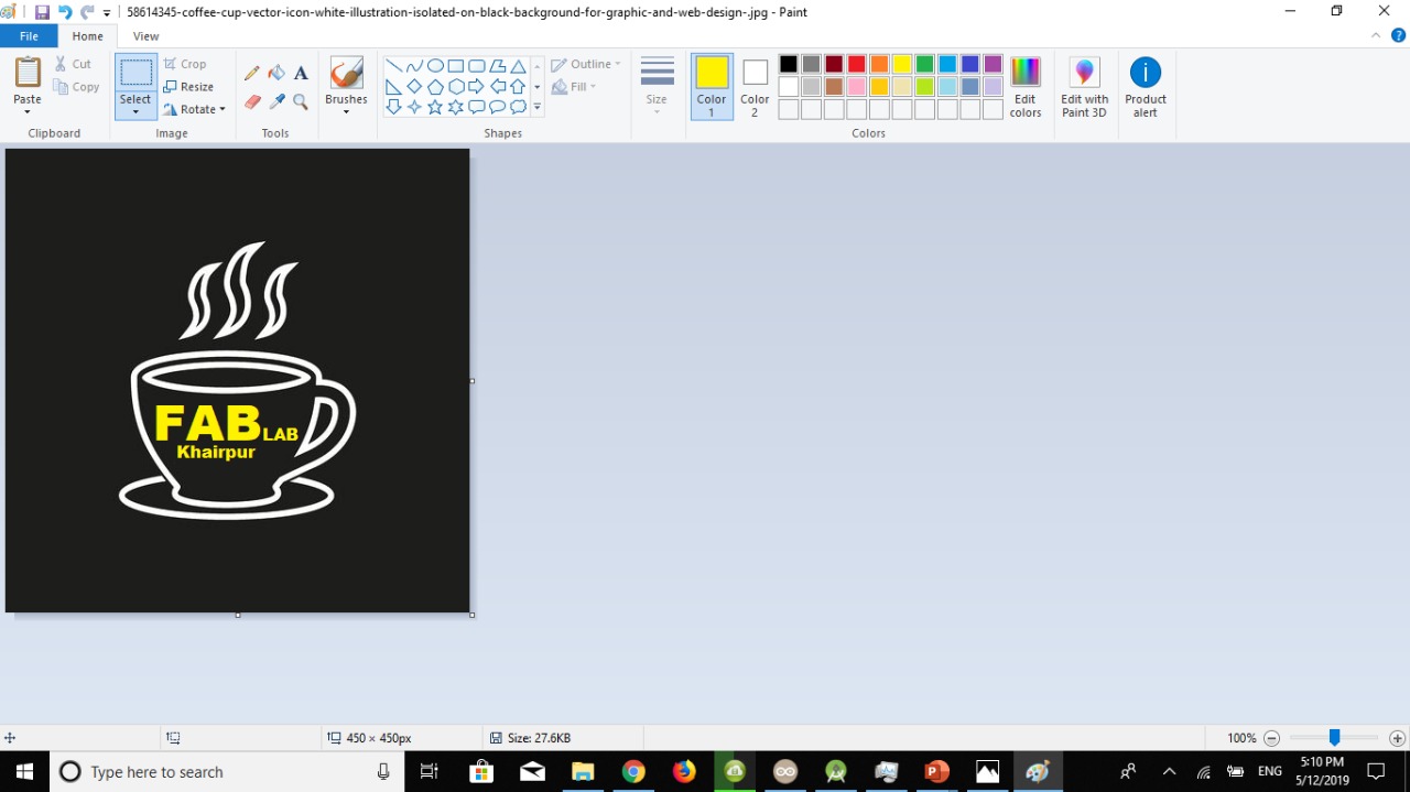
Here is look of the logo that I have esignd for App.
Logo
After Designing Logo for app the next I design some text for front page of mobile application. I make text FABCaFe Fab Lab Khairpur
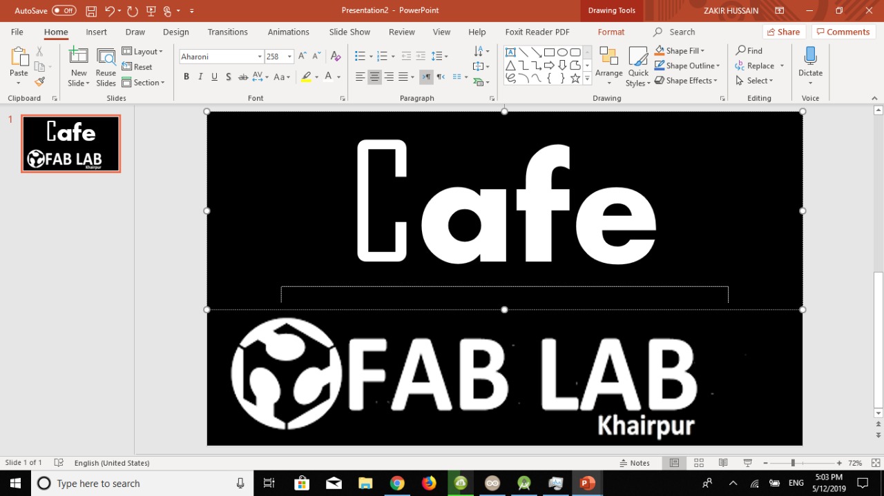
Microsoft Powerpoint
For desiging this text I used mirosoft powerpoint, I take logo and edit it.After Designing text I place this text in front page of my app.
Text View
I opened text view of the application and place text accordingly.
After Doing designing and Runing Application I have interfce my app with ESP12-E board that I have designed in Networking and Communication Week
ESP12-E
For commuication with my app I connect FTDI cable with Esp board and configure ESP as TCP Server.
Connecting FTDI
As I mentioned earlier that I made ESp12-E as TCP Server and all client within range of that (Server )can connect using Ip Address. For that client and Server must have same network connection.
I create a hotspot Network fom my laptop and set SSID and password for that network.
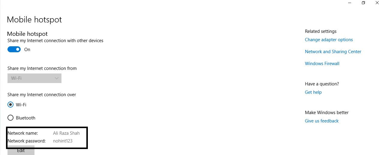
creating Hotspot
After creating hotspot I uploaded program and connect my app.
Select Setting
Code
Code
While Assembling
After assembling the table the next task that I did is to assemble each and everything and packging of table like fiting electronic circutry, 3d printed buttons, frame for rgb strips etc.
Condition During Week8 Assignment
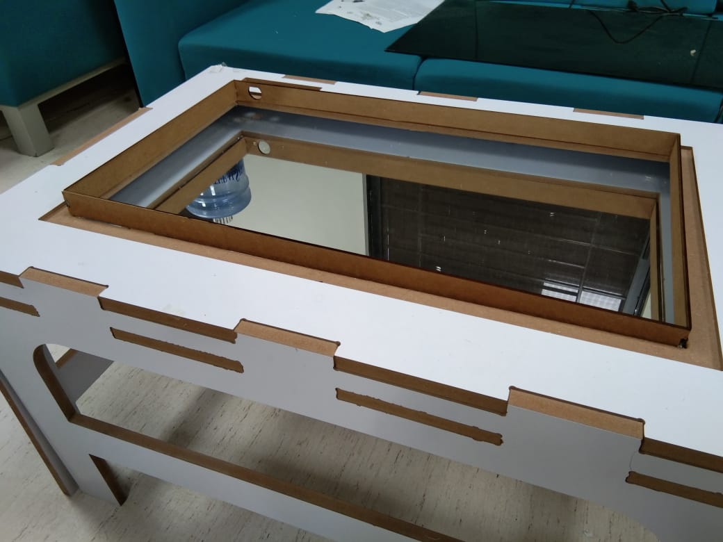
After that I reassemble the parts of the table buy mirror according to my requirement and placed inside the table.
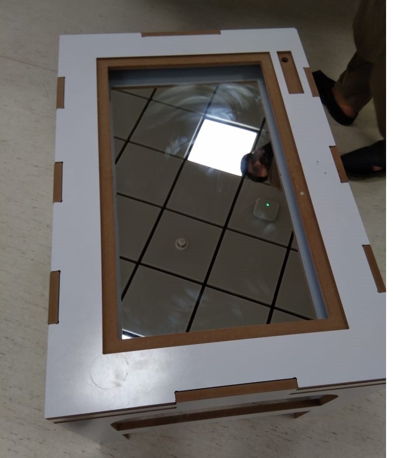
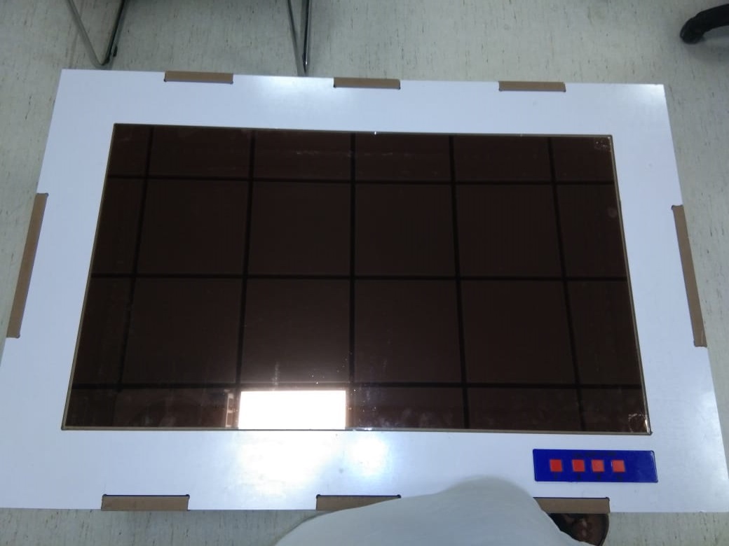
Table After Placing Mirror
The next step is to buy a glass and put solar film on one side of the glass. Following are the some images while placing solar film.
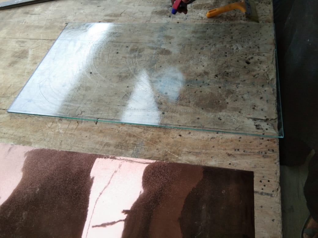
cleaning The Glass
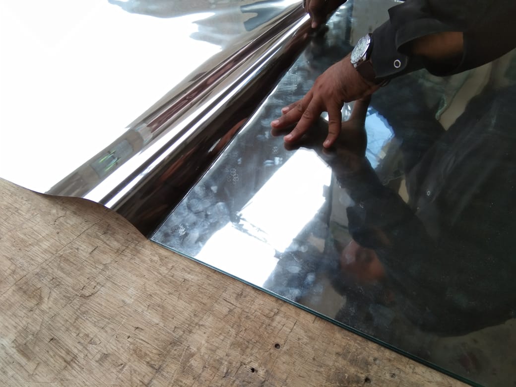
placed Plastic Cover
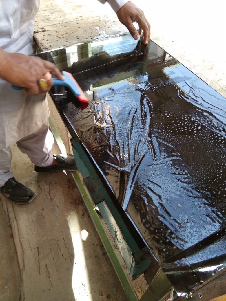
Remove Bubbles
After Covering With palstic
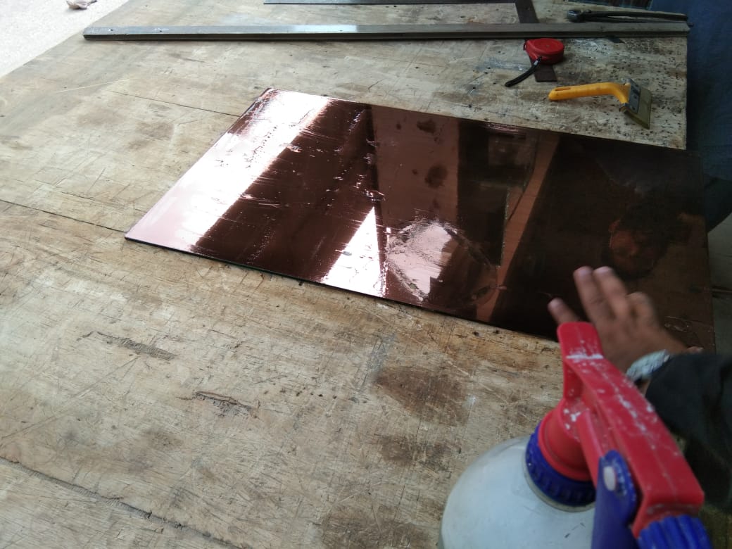
After packing Of Mirror & Glass
After That I design frame for Leds Strips . For that please visit this page with heading Frame for Led Strips
Bill Of The Material
| Components | Number of components * Price of components(USD) | Total price (USD) | link |
|---|---|---|---|
Acknowledgment:
Allah - beginning with the name of - the Most Gracious, the Most Merciful . All praise is due to Allah; we praise Him, seek His help, and ask for his forgiveness. I am thankful to Allah, who supplied me with the courage, the guidance, and the love to complete this course. Also, I can not forget the ideal man of the world and the most respectable personality for whom Allah created the whole universe, Prophet Mohammad(Peace Be Upon Him).
I would like to express my special thanks of gratitude to Professor Neil Gershenfeld, director of Fab Academy whose lectures increases our exposure and encourage us to learn more, specially thanks to Vice Chancellor Sir Professor Nisar Ahmed Siddqui along with his team whose vision and mission make FABLAB possible in Pakistan, local Instructors Sohail Ahmed, Noor Ahmed Pirwani and Rasheed Ahmed Qazi as well as Global Instructor Nuria Robles for reviewing my assignments. this wonderful learning Opertunity is also helped me in doing a lot of Research and I came to know about so many new things I am really thankful to them. Secondly I would also like to thank my parents and friends who helped me and motivate for to avail this learning opertunity.
You may Download All files from mention below Links
You may Download all files Related To Table here
Click Here For Main Board fILe
p>Download Andorid Studio Code From Here
You May Download ESP12-E Files and Code From Here
You May Download Final code From Here
You May Download 3d Printed Files From Here
You May Download Lasercut(Frame For Led Strip) Files From Here
.png)