
|

| Sukkur IBA University Khairpur Campus Merit, Quality, Excellence |
Week - 14
Networking and Communications
Assignment
Group Assignment
- send a message between two projects
Individual Assignment
- design, build, and connect wired or wireless node(s) with network or bus addresses
Group Assignment
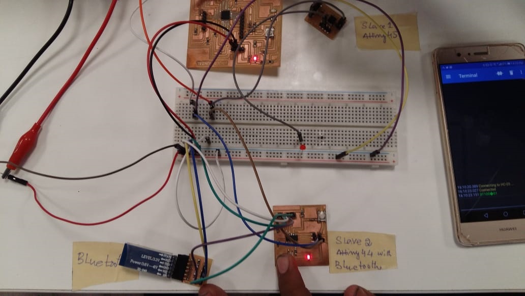
As a group assignment this week we used HC05 bluottoth module, connected it to atinny44. We then communicated with two slaves (slave 2 was atinny 44 with address 27 and slave 1 was atinny45 with address 26) making 328p the master. Hence led blinking every for one mili second shows the reception of data. Data here is just 0 and 1, and so led will just blink for 100ms. Connection can be seen below.
Next we used terminal as to see data received..
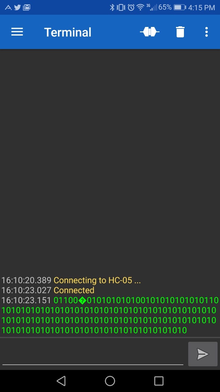
Below attached video illustrates working network. Note: Led on breadboard is attached to slave atinny45 as it didn't have any built in led.
Embedded Communication
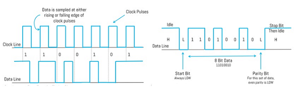
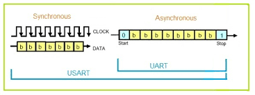
Embedded communication is the process of sending information between two MCUs or from one circuit to other. For a communication to happen there needs to be a transmitter and a receiver. Communication may be in one direction or in both directions, there are different classifications according to this, but the basic classification is Synchronous and Asynchronous communication.
Synchronous: means sender and receiver use the same clock signal. Asynchronous: means sender provides a synchronization signal to the receiver before starting the transfer of each message.
Synchronous & Asynchronous Data
Communication protocol
Communication protocols are formal descriptions of digital message formats and rules. They are required to exchange messages in or between computing systems and are required in telecommunications.
Communications protocols cover authentication, error detection and correction, and signaling. They can also describe the syntax, semantics, and synchronization of analog and digital communications. Communications protocols are implemented in hardware and software. There are thousands of communications protocols that are used everywhere in analog and digital communications. Computer networks cannot exist without them.
There are two types of communication protocols which are classified below:
1. Inter System Protocol
2.Intra System Protocol
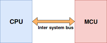
1.Inter System Protocol:
The inter system protocol using to communicate the two different devices. Like communication between computer to microcontroller kit. The communication is done through a inter bus system.
Different categories of Inter system protocol:
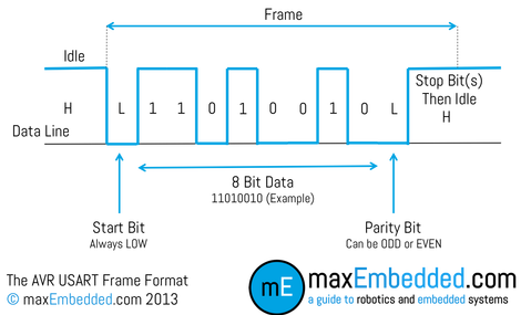
UART Protocol
UART stands for universal asynchronous transmitter and receiver .UART Protocols is a serial communication with two wired protocol .The data cable signal lines are labeled as Rx and Tx. Serial communication is commonly used for transmitting and receiving the signal. It is transfer and receives the data serially bit by bit without class pulses. Ex: Emails, SMS, Walkie-talkie.
USART Protocol
USART stands for universal synchronous and asynchronous transmitter and receiver. It is a serial communication of two wire protocol. The data cable signal lines are labeled as Rx and TX. This protocol is used to transmitting and receiving the data byte by byte along with the clock pulses. It is a full-duplex protocol means transmitting and receiving data simultaneously to different board rates. Different devices communicate with microcontroller to this protocol. Ex:-Telecommunications.
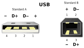
USB Protocol
USB stands for universal serial bus. Again it is a serial communication of two wire protocol. The data cable signal lines are labeled D+ and D-.This protocol is used to communicate with the system peripherals.USB protocol is used to send and receive the data serially to the host and peripheral devices.USB communication requires a driver software which is based on the functionality of the system.USB device can transfer data on the bus without any request on the host computer. Ex: Mouse, Keyboard, Hubs, switches, pen drive.
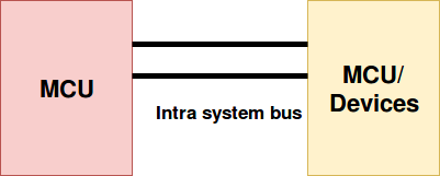
2.Intra System Protocol:
The Intra system protocol is used to communicate the two devices within the circuit board. While using this intra system protocols, with out going to intra system protocols we will expand the peripherals of the microcontroller. The circuit complexity and power consumption will be increases by using intra system protocol. Using intra system protocols circuit complexity and power consumption, cost is decrease and it is very secure to accessing the data.
Different categories of Inter system protocol
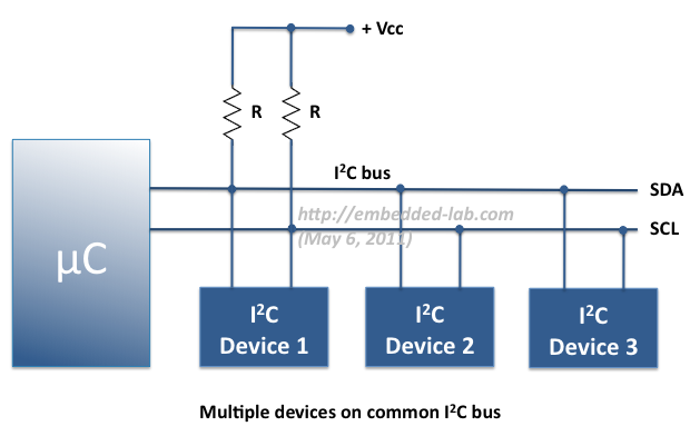
I2C Protocol
I2C stands for inter integrated circuit. I2C requires only two wires connecting all peripherals to microcontroller.I2C requires two wires SDA (serial data line) and SCL (serial clock line) to carry information between devices. It is a master to slave communication protocol. Each slave has a unique address. Master device sends the address of the target slave device and read/write flag. The address is match any slave device that device is ON, remaining slave devices are disable mode. Once the address is match communication proceed between master and that slave device and transmitting and receiving the data.
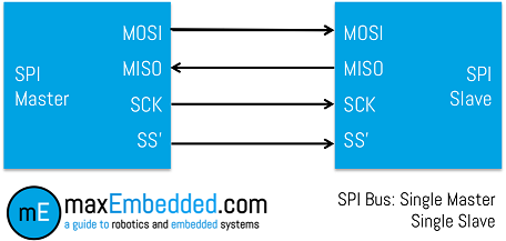
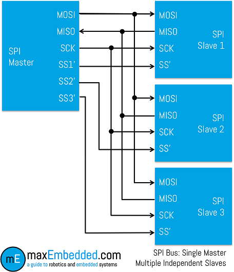
SPI Protocol
SPI stands for serial peripheral interface. It is one of the serial communication protocol developed by Motorola. Some times SPI protocol is also called a 4-wire protocol. It requires four wires MOSI, MISO, SS, and SCLK.SPI protocol used to communicate the master and slave devices. The master first configures the clock using a frequency. The master then selects the particular slave device for communication by pulling the chip select button. That particular device is selected and starts the communication between master and that particular slave. The master select only one slave at a time. It is full duplex communication protocol. Not limited to 8 bit words in the case of bit transferring.
CAN Protocol
CAN stands for controller area network .It is a serial communication protocol. It require two wires CAN High (H+) and CAN low (H-). It was developed by the Robert bosh company in 1985 for in vehicle networks. It is based on a message oriented transmission protocol.
Source-1
Source-2
Individual Assignment
For my final project, I will need to power Electric heater, so i decided to control Electric heater with HM-10 bluetooth via mobile application to ON/OFF the heater.
HM-10 programming and Contact
Bluetooth was too difficult to connect at first. So I studied by looking for datasheets for HM-11 and HM-10. I referred to it here on the site.
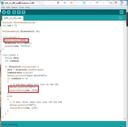
The HMP-10 is Bluetooth 4.0 and serial communication is available at 9600. When I send a serial through Bluetooth communication, Lamp is connected with 328p board which lights up and when I send it again, I wrote down a code that turns it ON/OFF.
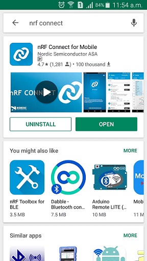
Enter the bluetooth connection code and check that the connection signal is received. Its name is HMSoft. Then download the nRF connector from Google Play. (I'm not sure if the iPhone goes down.)
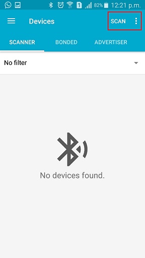
In the nRF application, press Scan to find the Bluetooth signal
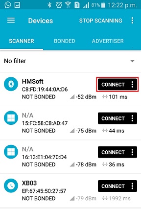
Connect An HMSoft. If the connection fails, connect it from the top to the connector again.
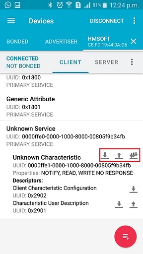
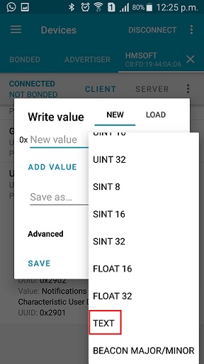
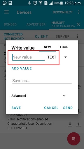
Then click UnKnown Service and press the emoticon at the end of the Characteristic line. (Bluetooth connection button.) Then click the up arrow next to it to call up the Write value window. Then press TEXT to set it.
I write my serial. I will turn the lamp which is connected 328p board, on and off by sending the letter "1" and "0" respectively.
I2C Communication
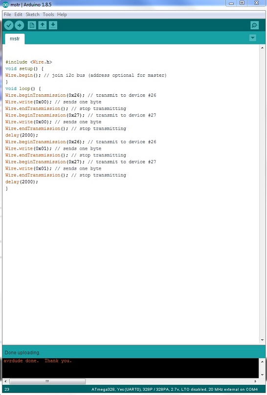
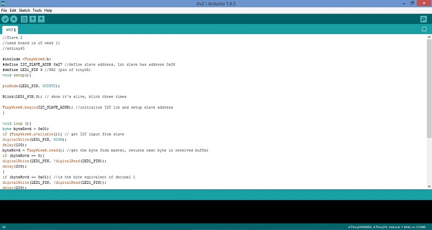
I used one board for Master and other two for Slaves. For master device, I used my atmega328p board which I designed in Week 12. . And, For Slave1, I used my board of attiny44 which I designed in Week 7. For Slave2, I used my board of attiny45 which I designed in Week 11 . For source code of slave and master, I explored the fab academy website and found my required source, then I modified the source bit according to my requirement. There are several libraries in arduino which supports this communication. For Master, I downloaded and installed "Wire.h" library, and for slave I downloaded and installed "tinywireS.h" library. Without installing these libraries I was unable to upload the code to the devices.
Code Uploading for Master board
Code Uploading for Slave1 board
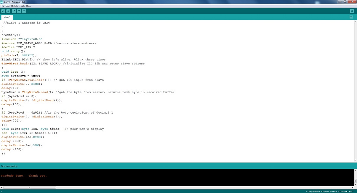
Code Uploading for Slave2 board
Video will illustrates the successful completion of I2C communication between Master and Slaves.
"Click here"to download all files of this week

Automatic Hot Water Dispenser by Tariq Ahmed Shaikh is licensed under a Creative Commons Attribution-ShareAlike 4.0 International License.
Based on a work at http://fabacademy.org/2019/labs/khairpur/students/tariq-ahmed/