|

| Sukkur IBA University Khairpur Campus Merit, Quality, Excellence |
Week - 6
3-D Scanning and Printing
Assignment
Group Assignment
•Test the design rules for your 3D printer(s)
Individual Assignment
•Design and 3D print an object (small, few cm3, limited by printer time) that could not be made subtractively •3D scan an object (and optionally print it)
Group Assignment
For group assignment, we are using .STL file which we found from thingivers.com the file is: here
Then we opened the (.stl) file in the Cura software 3.6.0, as you can see in the image below.
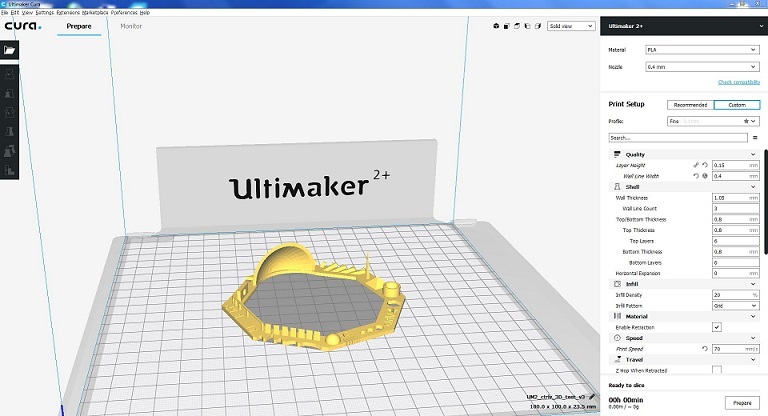
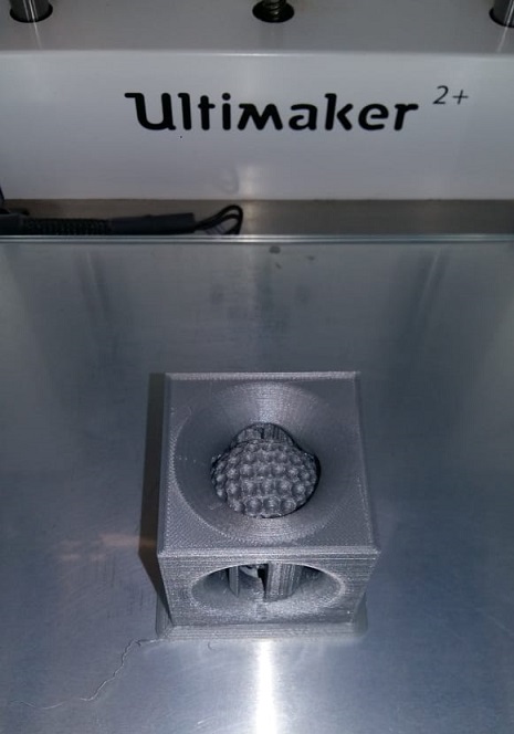
The insert cura file in (ultimate 2+) 3D printer
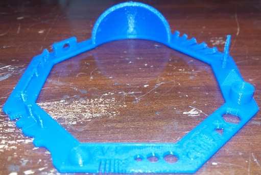
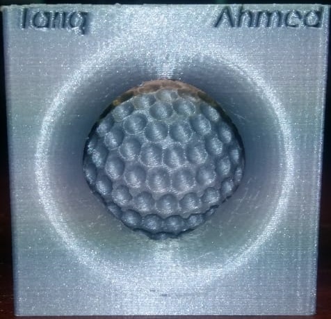
Here is our Final picture of our testcard.
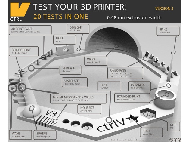
In this test we checked the machine calibration and it test how much precise the machine is. We have to check these parameters:
•Nut, Size M4 Nut should fit perfectly •Wave, rounded print
•Star, Sharp Edges
•Name, Complex Shapes
•Holes, Size 3, 4, 5 mm
•minimal Distance: 0.1, 0.2, 0.3, 0.4, 0.5, 0.6, 0.7 mm
•Z height: 0.1, 0.2, 0.3, 0.4, 0.5, 0.6, 0.7, 0.8, 0.9, 1.0, 1.1 mm
•Wall Thickness: 0.1, 0.2, 0.3, 0.4, 0.5, 0.6, 0.7 mm
•Bridge Print: 2, 4, 8, 16 mm
•Sphere, Rounded Print 4.8mm height
•Sphere Mix, 7 mm height
•Pyramide, 7 mm height
•Overhang: 25, 30, 35, 40, 45, 50, 55, 60, 65, 70°
•3D Print Font, optimized for 3D printing
•Size, 100 x 100mm x 23.83 (10mm width)
•Spike, minimum Layer Time, 21 mm height from Bottom (include Baseplate)
•Hole in Wall, 4 mm diameter, check for proper print
•Raft Test, raft should be just under the model
•Retract Travel, check retract settings for longer travel
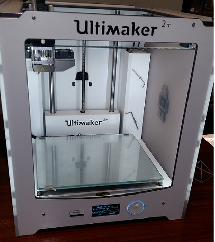
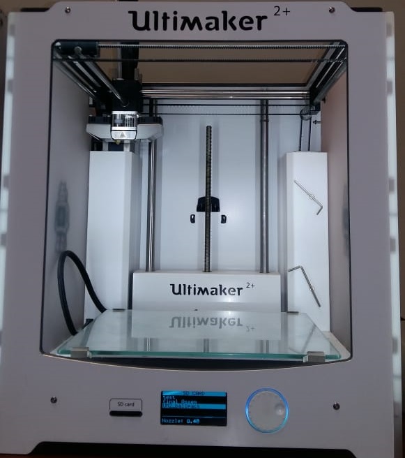
In FabLab Khairpur we have Ultimaker 2+ and Ultimaker Extended 2+, we set infill to 30 %, layer height to 0.1mm and 0.4mm nozzel. In this testcard we learn
•It is better to calibrate 3D Printer before giving job, otherwise test results may effect. •3D Printers have different efficiency, which can be measured by giving same file with same settings to different type of 3D Printers
Advantages of 3D Printing
Customization- A major advantage in 3d printing. With just a raw material, a blueprint and a 3d printer, one can print any design no matter how complex it might be.
Constant Prototyping and Increased Productivity – It enables quick production with a high number of prototypes or a small-scale version of the real object in less time than using conventional methods. This helps designers to improve their prototypes, for any design flaws that may affect the quality of the product.
Affordability – The initial cost for setting up a 3d printing facility is definitely high; however, it is much cheaper compared to labor costs and manufacturing costs while using the conventional way. Adding to it, is the fact that the cost of producing or manufacturing products using 3d printing technology is equal for small-scale and mass manufacturing.
Storage – Traditional manufacturing produces additional products that you probably know you will eventually need thus storage problems arise. However, 3d printing technology, products can be “printed” when needed thus excess products are eliminated and no storage cost is required.
Employment Opportunities – The widespread use of 3d printing technology will definitely increase the demand for engineers who are needed to design and build these printers. Technicians who are skilled at troubleshooting and maintenance and Designers to design blueprints for products and more jobs will be created.
Health Care – With the advancement of technology, a customizable human body parts and organs can now be manufactured this technology is termed as Bioprinting. Although right now this is still experimental, the potential is huge. This breakthrough will not only address the shortage of organ donors, but also organ rejection since the organs that are built will consist of the patient’s unique characters and DNA.
Disdvantages of 3D Printing
Decrease in Manufacturing Jobs – The decrease in manufacturing jobs will greatly affect the economy of countries that rely on a large number of low skill jobs.
Limited Size – The size of objects created with 3d printers is currently limited however, in the near future; large items such as architectural structures can be created using 3d printing.
Limited Raw Materials – Traditional manufacturing of products has an enormous range of raw materials that can be used. Presently 3d printers can work up to approximately 100 different raw materials and creating products that uses more raw materials are still under development.
Violation of Copyrights – The biggest disadvantage of 3d printing is Counterfeiting. Anyone who gets a hold of a blueprint will be able to counterfeit products easily. It will become more common and tracing the source of the counterfeited items will be nearly impossible. Many copyright holders will have a hard time protecting their rights and businesses producing unique products will suffer.
Production of Dangerous Items – With 3d printers, plastic knives, guns and any other hazardous objects can be created. It makes easier for terrorists and criminals bring a weapon without being detected.
Individual Assignment
- Design and 3D print an object (small, few cm3, limited by printer time) that could not be made subtractively
- 3D scan an object (and optionally print it)
Design and print a 3D model
For the 3D printed object, I want to make different objects to use more commonds as much as i can use in solidworks,SolidWorks software have huge applications especially in engineering field, which will help me in designing during diploma and after diploma,thats why i use solidworks software for desinging. The first step is to make the 3D model in SolidWorks.
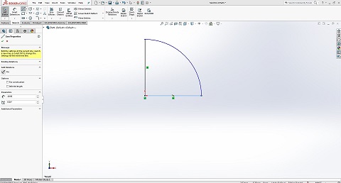
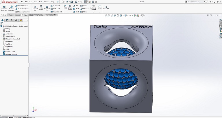
Designing Golf Ball
I started with sketch to make a arc of 10mm on front plane and joined by line,make sure the bottom line of sketch should be in horizontal.
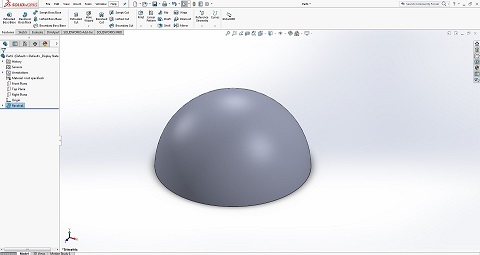
Then go to feature and revolve the object, and you can choose any color from right corner click Appearance
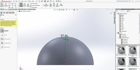
Go to front plane,draw center line and select outerline then click convert entities now it is converted. (Convert Entities. You can create one or more curves in a sketch by projecting an edge, loop, face, curve, or external sketch contour, set of edges, or set of sketch curves onto the sketch plane. Original part. Sketch plane above part. Loop of edges projected onto plane using Convert Entities.) Now draw a line on half circle and arc the sizes are 1 mm and 1.25mm respectively.Make center line and arc tangent. After that go to trim commond and choose power trim,then press left key and drag on circle(The Trim Entities tool is mainly used for removing unwanted parts or portions from your design sketch)
After that go to revolve cut, select verticle line and axis.
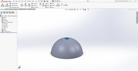
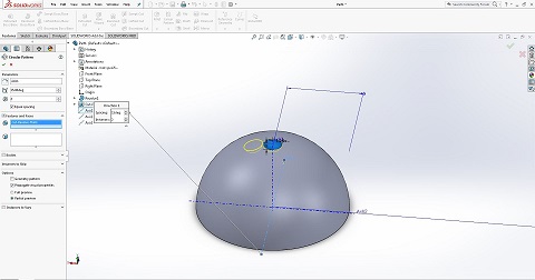
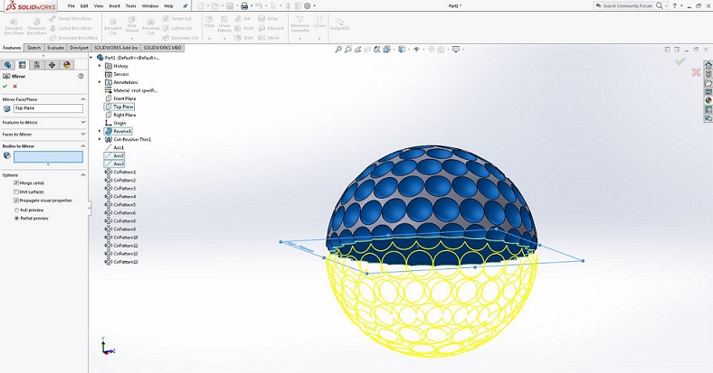
Then go to geometry reference make axis on top and right plane,same way make axis on front and top plane,again make axis on front and right plane. Now select axis1 and go to circular pattern,make 15° spacing and 2 numbers instances, then select cut revolve in feature and faces.
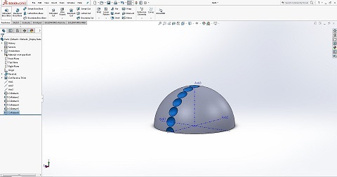
Same Method, select axis1 and go to circular pattern,make 30°/45°/60°/75°/90° spacing and 2 numbers instances, then select cut revolve in feature and faces.
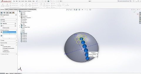
After that select Axis3 and go to circular pattern,make 360° spacing and 6 numbers instances,then select circular pattern1 in feature and faces.
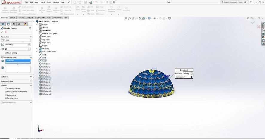
Same method, select Axis3 and go to circular pattern,make 360° spacing and 12/18/21/24/27 numbers instances,then select circular pattern2/3/4/5/6 in feature and faces.
Hide the axis then go to top plane and click Mirror commond,to make full circle.
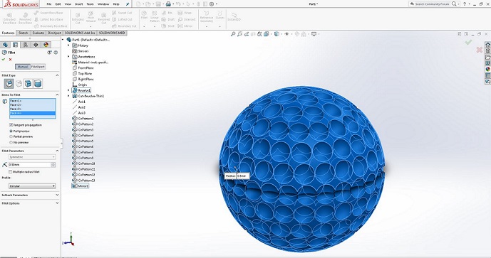
Go to fillet, select face and choose 0.5mm as radius.
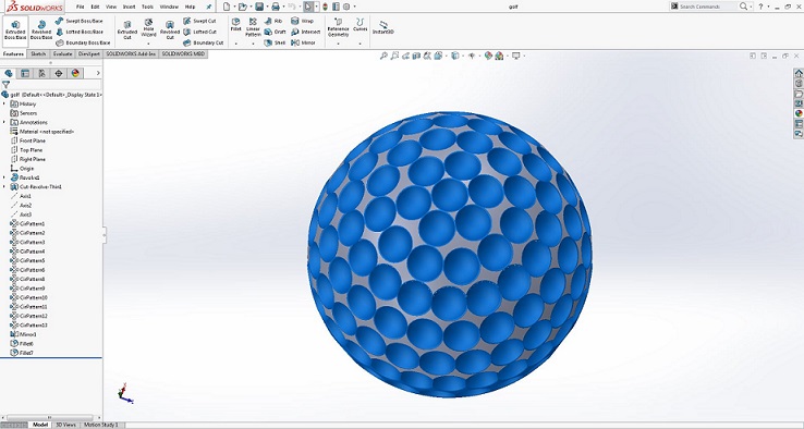
Here is final picture of Golf ball.
Here is a helpful link for this process
Designing a Square
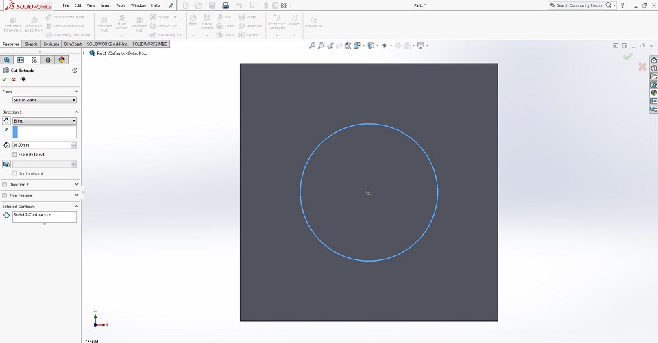
Draw a square of 30 x 30 mm.
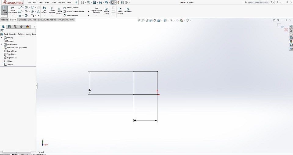
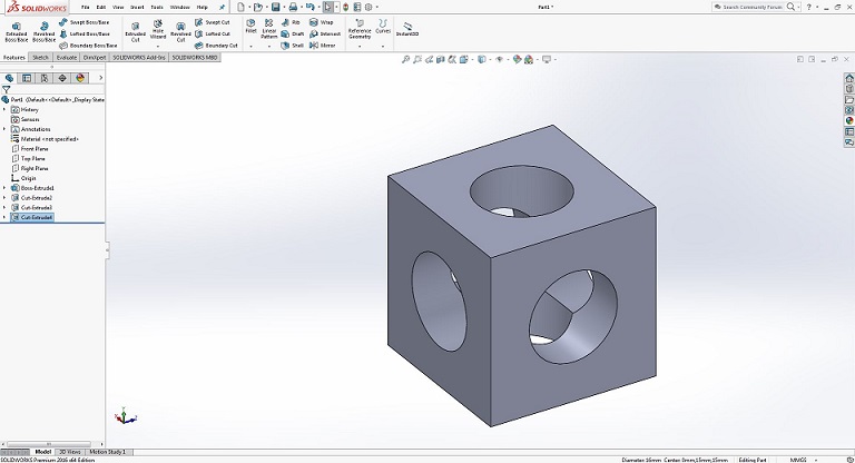
then extrude square to 30 mm, draw a center line on it and draw a circle from center point with radius of 16mm for extrude cut.
Same method, Extrude cut other sides of square.
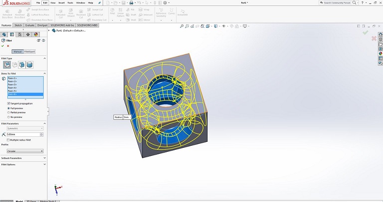
After that go to fillet commond, to make corners fillet face with radius of 5mm
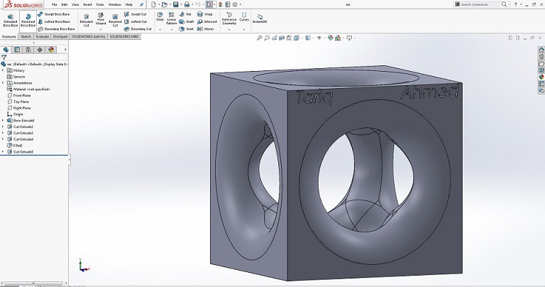
Here is final picture of Square with Text extrude cut.
Now assemble both parts,go to solidworks open new assemblely file.
after that, save as parts file then open it and again save as .stl file. Now open .stl file in cura software
Quality
Layer height (mm)- The larger your layer height is the longer the print time takes. If you make your layer heights to small you may end up with gaps in your model. I chose 0.15 mm because it is suitable layer height for both printing time and structure support.
Shell thickness(mm)- Is the thickness of the outer shell of your model I chose 1.05 mm.
Fill
Bottom/top thickness(mm) – This controls the thickness of the bottom and top layers, the amount of solid layers put down is calculated by the layer thickness and this value. I chose a thickness of 0.8mm
Fill Density(%)- Controls how strong the part becomes. Usually set at 20%. For a solid part density is set to 100% and if part is empty it is set to 0%. I chose 20% for my Extractor. because I did not want it to be fully solid.
Speed and Temperature:
Print Speed (mm/s)- Affects the quality of your print. The slower the speed the higher the quality is and the faster the quality gradually gets worse. I chose a print speed of 70 mm/s.
Support:
Support type- There are 3 different support settings. None creates no support, touching build plate only creates a support where the support structure will touch the build platform and the final one is everywhere which creates support from top to bottom. I chose support density 5% because it can be remove easily.
Platform adhesion type
This allows the filament to flow through the nozzle before it starts printing your model. Which allows for a smoother transition into your first layers. The two options are skirt and brim. I used the brim option because my model didn’t have a lot of contact with the bed.
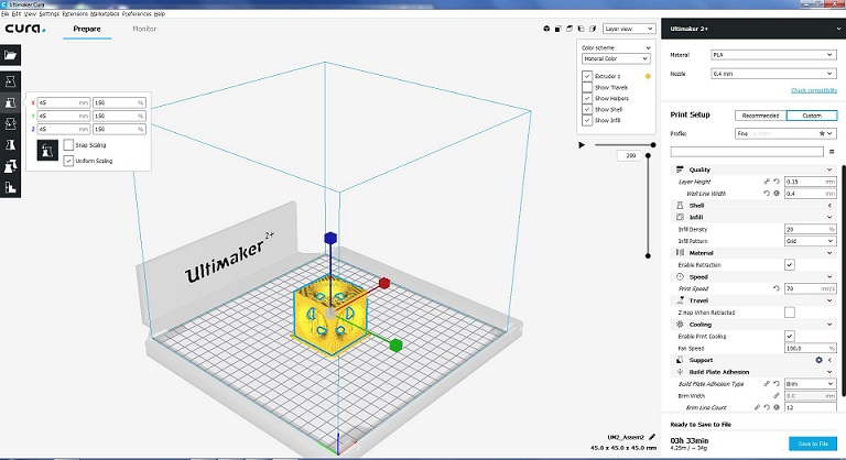
I scaled up upto 150% because it's size was small, it increased from 30x30x30 to 45x45x45mm, it took 3 hours and 33 minutes to print, and was used 4.25 meter and 34 grams of PLA (polylactic acid).
Here is a helpful link for this process
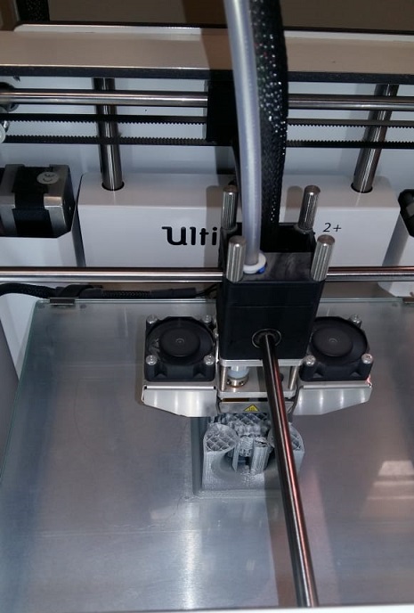
When 3D printer started
I then took another picture after some time so I could make sure that my model was printing correctly.
Some hours later, the extractor completed printing.I really liked the results, the extractor was as perfect as I designed it to be.
Final job after removing support.
Calibration of Ultimaker 2
I used these exact steps for my project these are the same steps copied from this link
Bed Leveling:
After the “Welcome” screen, the Ultimaker 2 will guide you through some steps for calibrating the build plate. For printing it is very important that the first layer is nicely squished into the glass plate and sticks well to it. If the distance between the nozzle and build plate is too big, your print won’t stick properly to the glass plate. On the other hand, if the nozzle is too close to the build plate it can prevent the filament from extruding from the nozzle.
Before the bed leveling can be done, the Ultimaker 2 will first do the "homing". This means that it will move the print head to the left back corner and the build plate towards the bottom, in order to set the origin point. After this, you can follow the next steps for leveling the build plate.
Setting the height:
The first step is to roughly level the build plate by rotating the button at the front of your Ultimaker 2 until there is approximately 1 mm distance between the nozzle and build plate. The measurement here is not critical, just make sure that the nozzle is close to the build plate without touching it.
Rough Leveling:
Next, a rough adjustment will be done on the front left and right side by turning the build plate screws. Turning the build plate screws to the left means that the build plate will get closer to the nozzle. Again, there should be approximately 1 mm between the nozzle and build plate.
Fine-tuning:
The last step will be fine-tuning of the build plate with the calibration card. Place the calibration card in between the nozzle and build plate on all 3 points and adjust the build plate screws until you feel slight friction when moving the card.
Ultimaker 2 Specifications:
Build Volume: 223 mm × 223 mm × 205 mm Layer resolution: up to 20 microns Print Speed: 30 mm - 300 mm/s Travel speed:30 mm - 300 mm/s Filament diameter: 2.85 mm recommended Nozzle diameter: 0.4 mm swappable Operating nozzle temperature: 180°C - 260°C Operating heated bed temperature: 50°C – 100°C Frame Dimensions: 342 x 493 x 588 mm Printer technology: Fused Filament Fabrication (FFF) Software: Cura
3D Scanning:
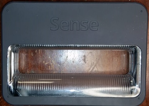
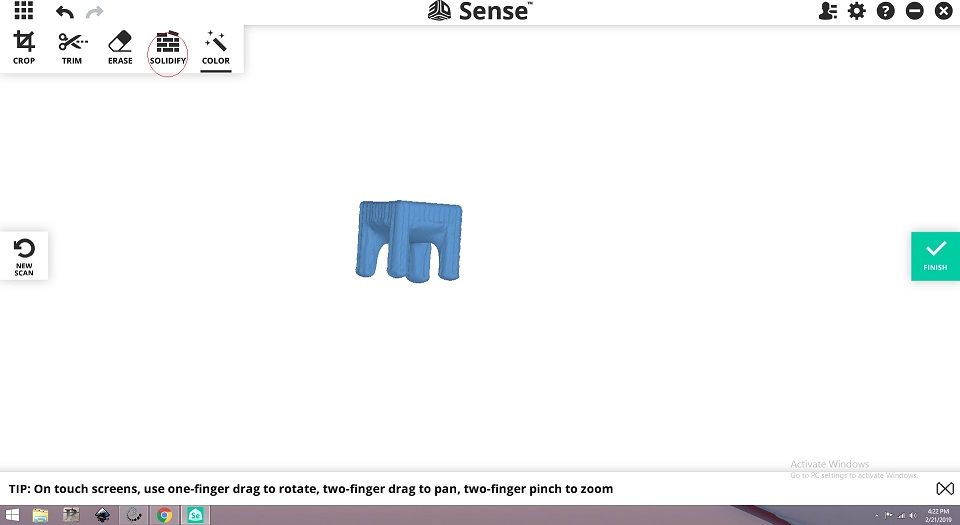
Sense
One of the assignments for this week was to make a scan of what you printed using the 3D printer. I used the Sense scanner and software name is Scense 3D Scanner, to scan object. The machine and software has limitations on what it can scan. Its limitations include scanning details such as rolls and internal parts.
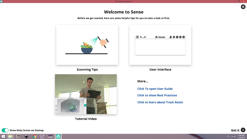
first step is to open sense software
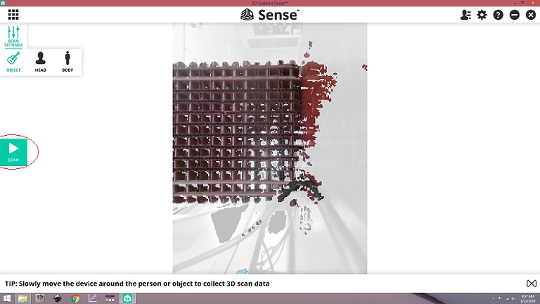
Second step is click to start scaning
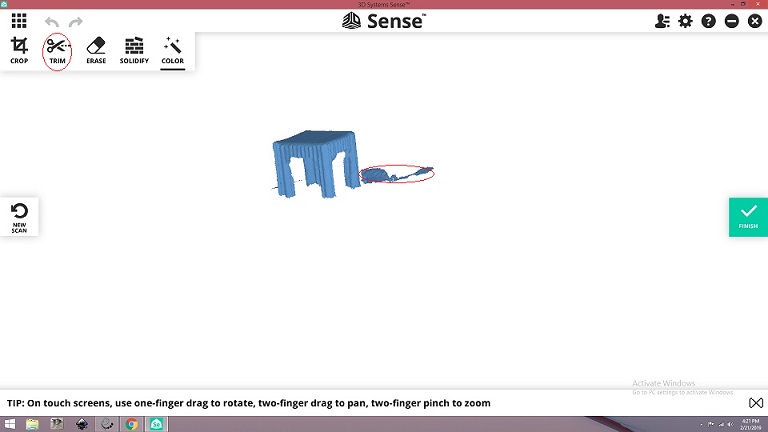
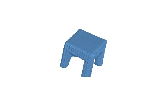
When scaning complete,use trim tool to remove unwanted objects
Then go to solidify tool to make solid.
Now you have solidify design.
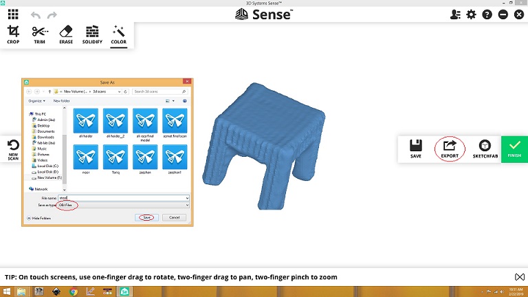
After that you are ready to save the file as (.obj)
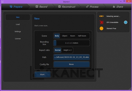
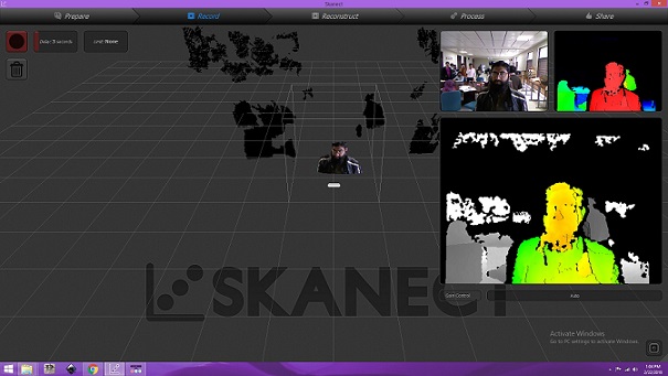
Skanect
<The software was pretty simple to use and didn’t require any tutorials,Once the program was started the software looks for any connected scanning devices. Then you can create your new project by clicking the new button. This offers a variety of option that you can select depending upon the nature of the scanning.I used kinect as scanner.
After opening software click on Record button(red button).
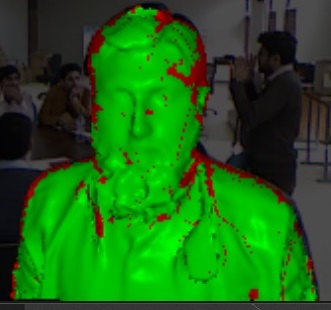
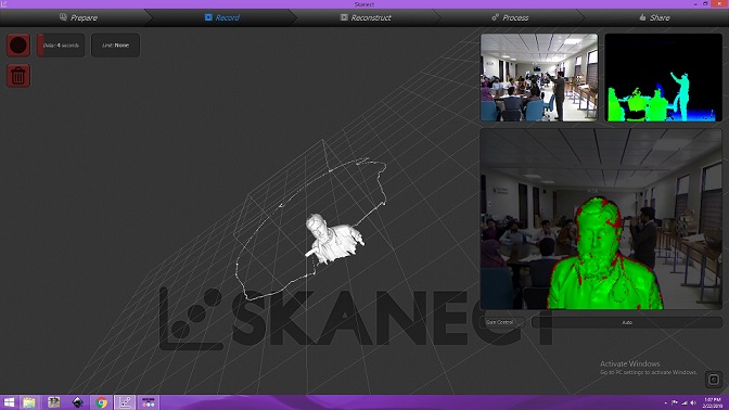
Move slowly and precisely to record video, stop and wait if red color comes on screen
Press red button when circular scanning is complete, After processing the reslt will be shown:
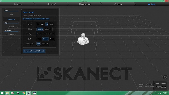
In Share tab select .STL as format and scale as millimeter and click on export preview and save it
"Click here"to download all files of this week
« Week5 Week7 »
Automatic Hot Water Dispenser by Tariq Ahmed Shaikh is licensed under a Creative Commons Attribution-ShareAlike 4.0 International License.
Based on a work at http://fabacademy.org/2019/labs/khairpur/students/tariq-ahmed/