
Input devices
So it's the 11th week since I begin my fab journey. In this week, I got following assignments,
- Measure something: add a sensor to a microcontroller board that you have designed and read it
- Probe an input device's analog levels and digital signals
Input devices
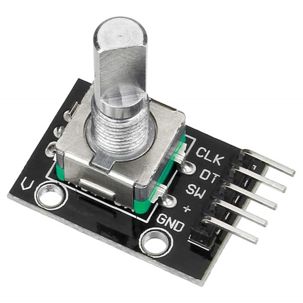
Rotary Encoder
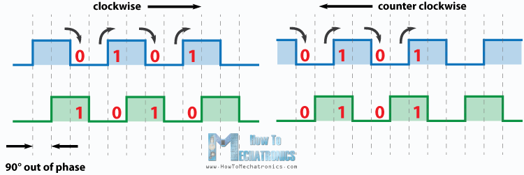
A rotary encoder is a type of position sensor which is used for determining the angular position of a rotating shaft. It generates an electrical signal, either analog or digital, according to the rotational movement. This rotary encoder is also known as quadrature encoder or relative rotary encoder and its output is a series of square wave pulses
In computing, an input device is a piece of computer hardware equipment used to provide data and control signals to an information processing system such as a computer or information appliance. Examples of input devices include keyboards, mouse, scanners, digital cameras and joysticks.
So in this week I have desided to make a Rotary encoder which was commonly use for selection . I am going to use a rotary encoder for that
PCB Design
i design my PCB in Proteus, This week is not a task for me. I have some experience in PCB design and Embeded
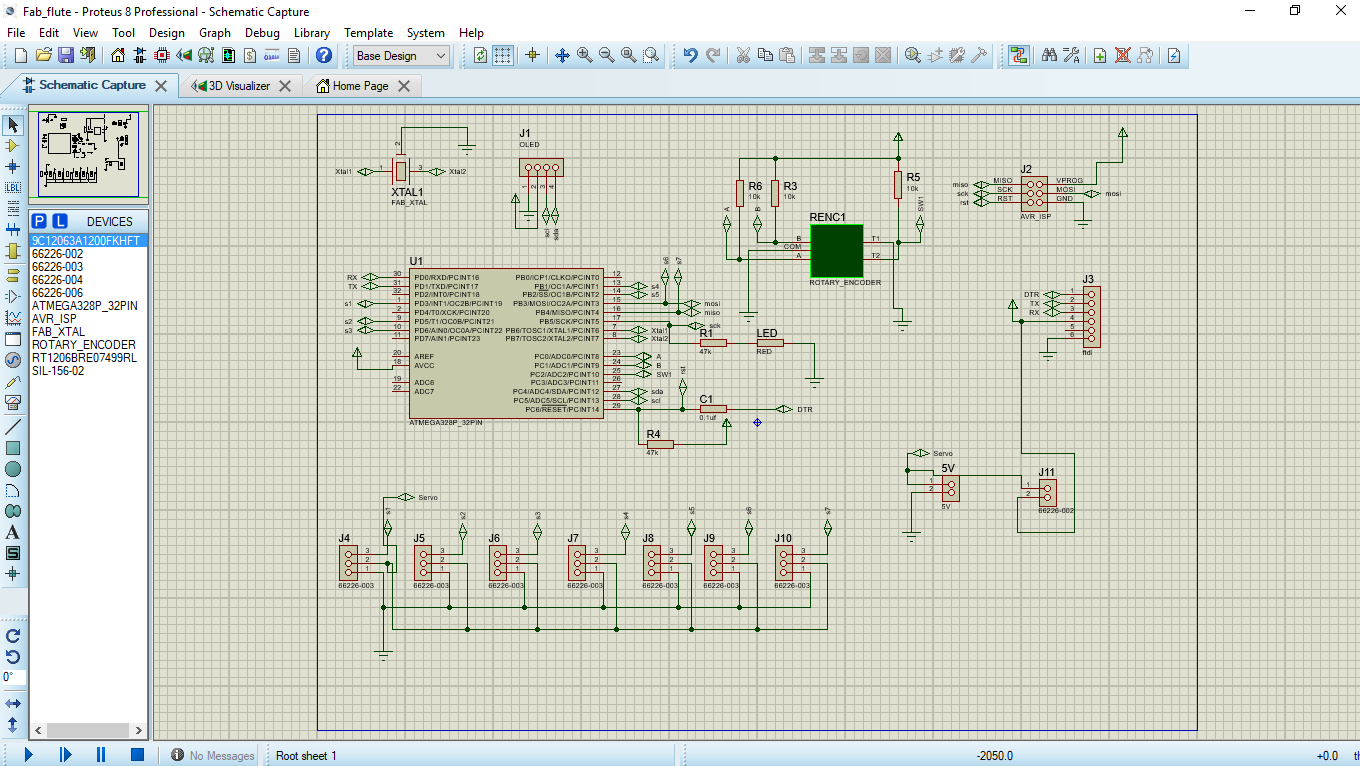
i route the tracks using proteus 8.0;
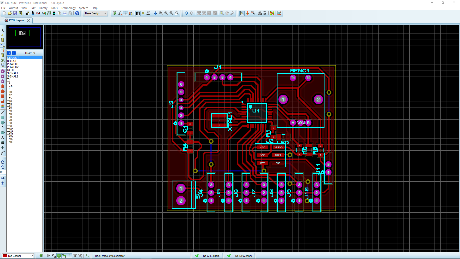
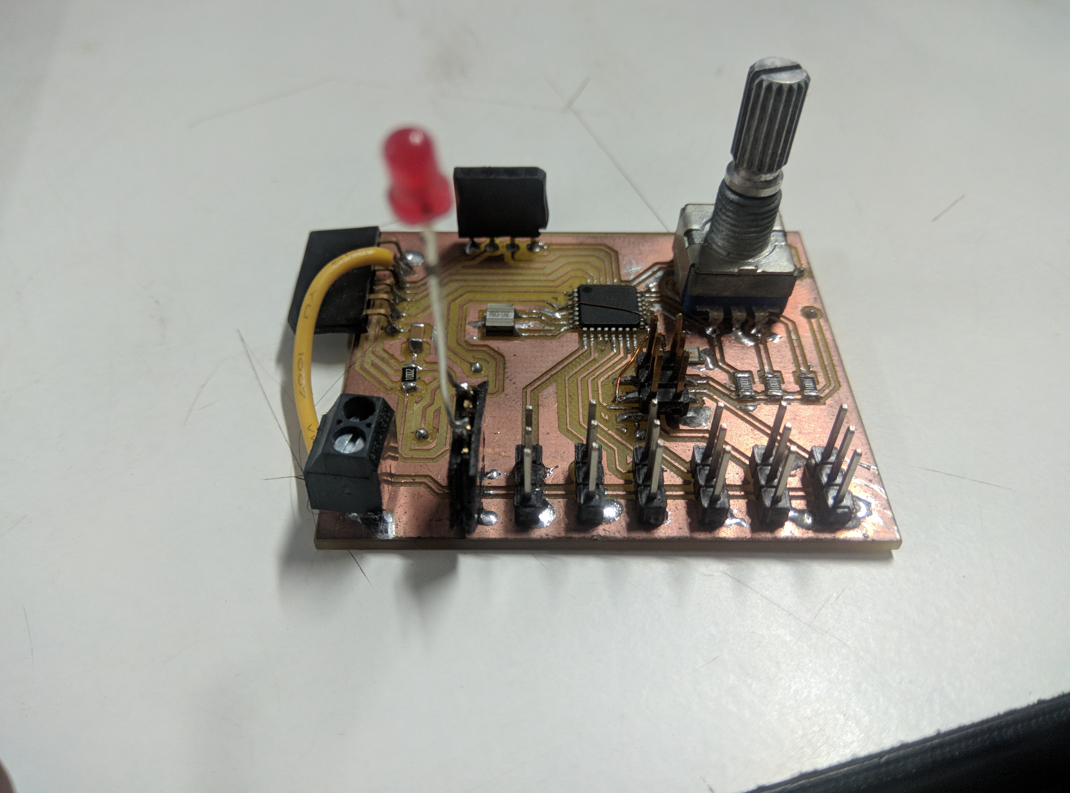
This is the PCB i made.
Download proteus PCB design files
PCB milling
You can refer my Electronics Production week to learn, how to use modella to mill PCB
Programing
I use Arduin ide to program my board. In this program we can adjest the brightness of LED using Rotary encoder. And this rotary encoder also have a PUSh feature. In this program, if we push encorder chaft BLUE LED on the board will glow. To turn off push it again.
  #define rotA A1
  #define rotB A0
  #define butt A2

  int counter = 150;
  int aState;
  int aLastState;
  int flag = 1;

  unsigned long lastDebounceTime = 0;
  unsigned long debounceDelay = 50;
  int ledState = HIGH;
  int buttonState;
  int lastButtonState = LOW;
  const int buttonPin = 0;
  const int ledPin = 13;

  void setup() {

    pinMode (rotA, INPUT);
    pinMode (rotB, INPUT);
    pinMode (butt, INPUT);

    pinMode (3, OUTPUT);
    pinMode (13, OUTPUT);

    aLastState = digitalRead(rotA);
  }

  void loop() {
    aState = digitalRead(rotA);
    switc();
    if (aState != aLastState) {
      if (digitalRead(rotB) != aState) {
        counter ++;
      } else {
        counter --;
      }

      if (counter > 255)
        counter = 255;
      if (counter < 0)
        counter = 0;
      analogWrite(3, counter);

    }
    aLastState = aState; // Updates th
  }

  void switc()
  {
    int reading = digitalRead(buttonPin);
    if (reading != lastButtonState)
    {
      lastDebounceTime = millis();
    }

    if ((millis() - lastDebounceTime) > debounceDelay)
      if (reading != buttonState) {
        buttonState = reading;


        if (buttonState == HIGH) {
          ledState = !ledState;
        }
      }
    digitalWrite(ledPin, ledState);
    lastButtonState = reading;
  }
Final board
Group assignment
Probe an input device's analog levels and digital signals So I measured the the analog and digital values of the "Hall Effect Sensor". For that we upload the following code to ATtiny 45. board and drsign files can be downlod from his page.
                              #include <SoftwareSerial.h>
                              int sensorPin = 1;// hall effect sensor
                              int digitalValue = 0;// variable to store the value coming from sensor
                              int analogValue = 0;
                              SoftwareSerial Serial(3, 4);
                              void setup()
                              {
                                pinMode(sensorPin, INPUT_PULLUP);

                                Serial.begin(9600); // initialize serial communications at 9600 bps

                              }
                              void loop()
                              {
                                digitalValue = digitalRead(sensorPin);
                                analogValue = analogRead(sensorPin);
                                Serial.print("Digital Value ");
                                Serial.println(digitalValue); //print the value of sensor in digital
                                delay(1000);
                                Serial.print("Analog Value ");
                                Serial.println(analogValue); //print the value of sensor in analog
                                delay(1000);
                              }
The analog signals are varying when the magnet is bring closer to the sensor. The values are given below

we also confirmed the working using a DSO.
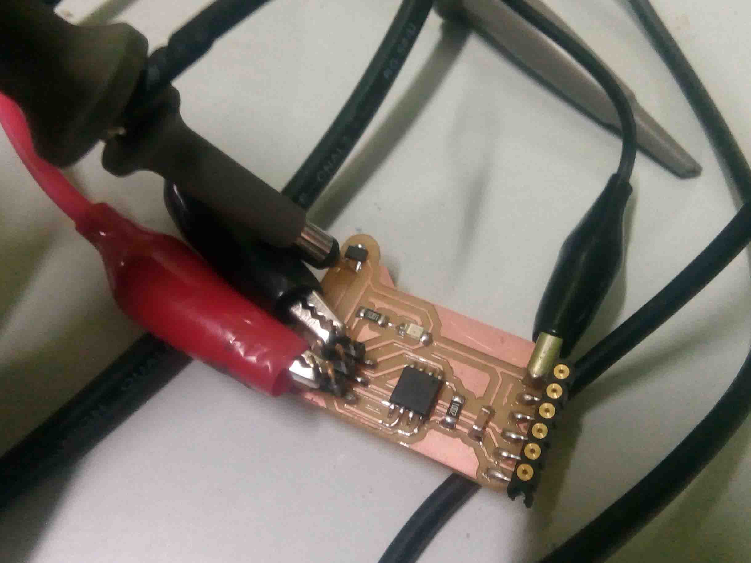
Here is the video..