Computer Controlled Cutting
This Week's Assignment
Group assignment: make lasercutter test part(s), varying cutting settings and slot dimensions
Individual assignment (1): Cut Something on the vinyl cutter.
Individual assignment (2): design, make, and document a parametric press-fit construction kit.
Vinyl cutter
A vinyl cutter is a type of computer-controlled machine. Small vinyl cutters look like a desktop printer. Like a printer controls a nozzle, the computer controls the movement of a sharp blade over the surface of the material. This blade is used to cut out shapes and letters from sheets of thin self-adhesive plastic (vinyl). The vinyl can then be stuck to a variety of surfaces depending on the adhesive and type of material. The one major limitation with vinyl cutters is that they can only cut shapes from solid colours of vinyl. A design with multiple colours must have each colour cut separately and then layered on top of each other as it is applied to the substrate. Also, since the shapes are cut out of solid colours, photographs and gradients cannot be reproduced with a stand alone cutter. In our fab lab, we use Roland Camm-1 vinyl cutter.
Cutting using Vinyl Cutter:
Vinyl cutter is one the most interesting machine. For cutting something on the vinyl, you need to (1) Set your machine and (2) Prepare your file.
Preparing your file:
I prepared my file in Photoshop.
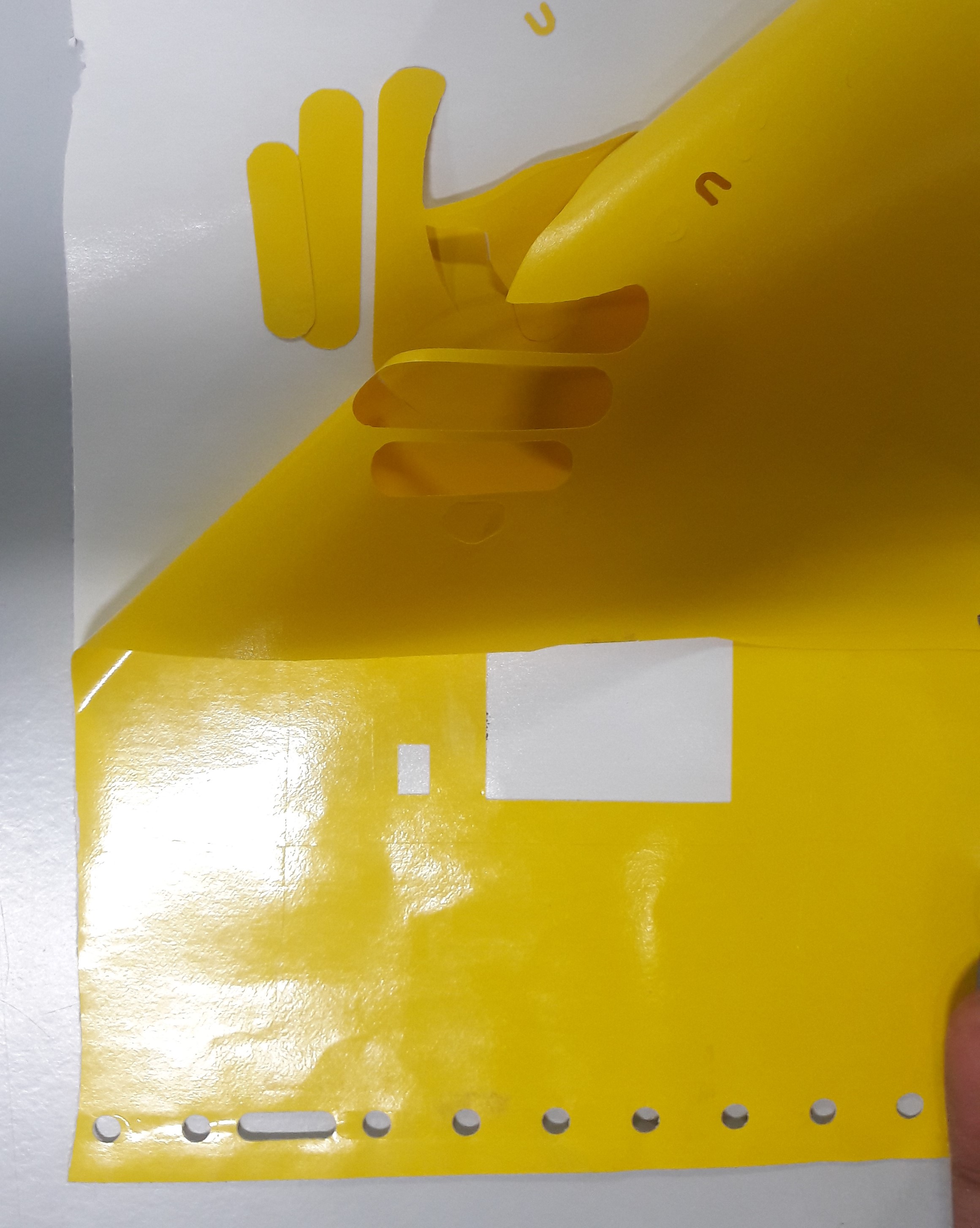
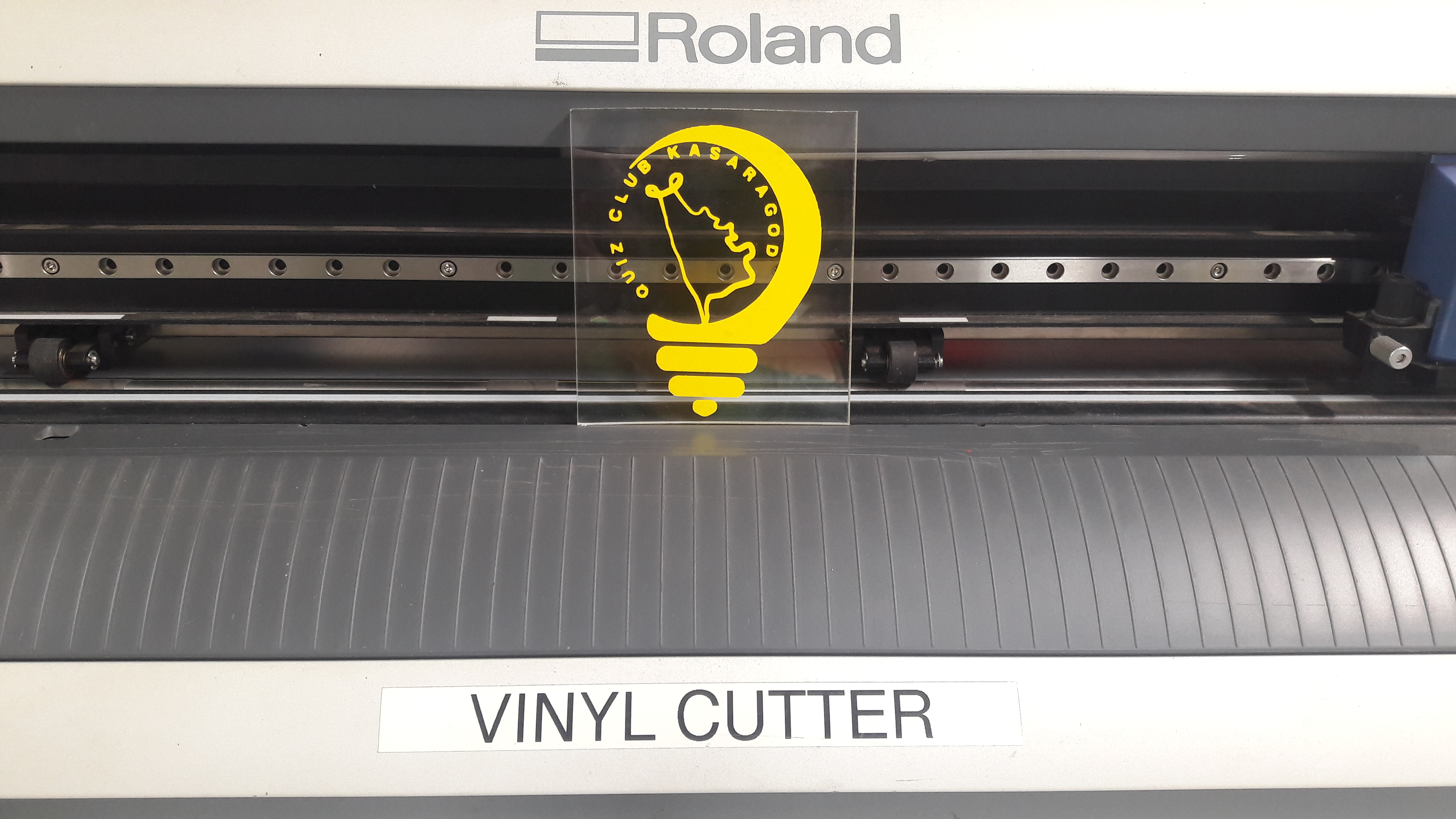
I thought of printing the logo of quiz club Kasaragod, which I am actually working on its logo editing.
I have made the image size 10 x 10 cm.
My actual logo colour was set in yellow and I directly saved the file in png and loaded in the desktop for vinyl cutting. But attend failed due to the colour.
Once again I worked on the Photoshop file and made everything into black and loaded the edited file into the desktop for printing.
Then i saved the file into my desktop.
You can download the whole project from here.
Setting your machine:
1. Fix your sheet to the machine and make sure the rolls are placed correctly on the white marks (the start must be within the main white mark "placed to your extreme right"). These marks play the role of the sensors that measure your sheet and gives you the dimensions within which you'll implement your design.
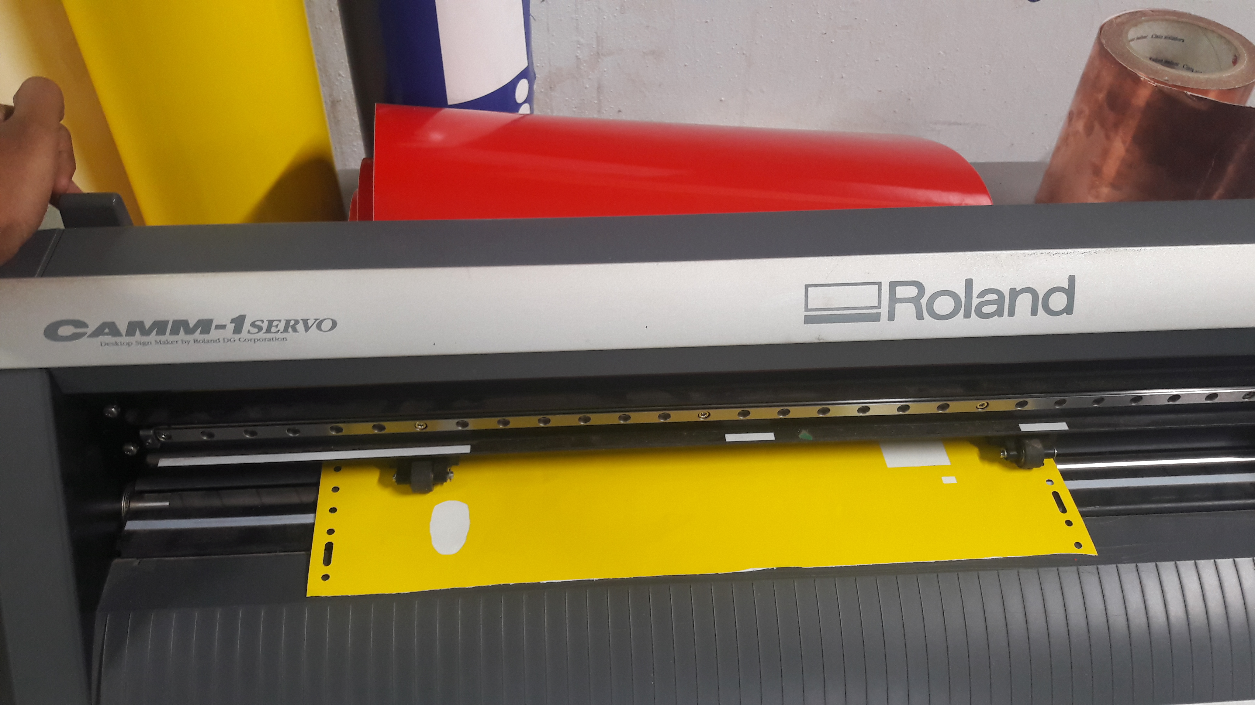
2. Open the machine and select your work piece (Roll, piece or edge).
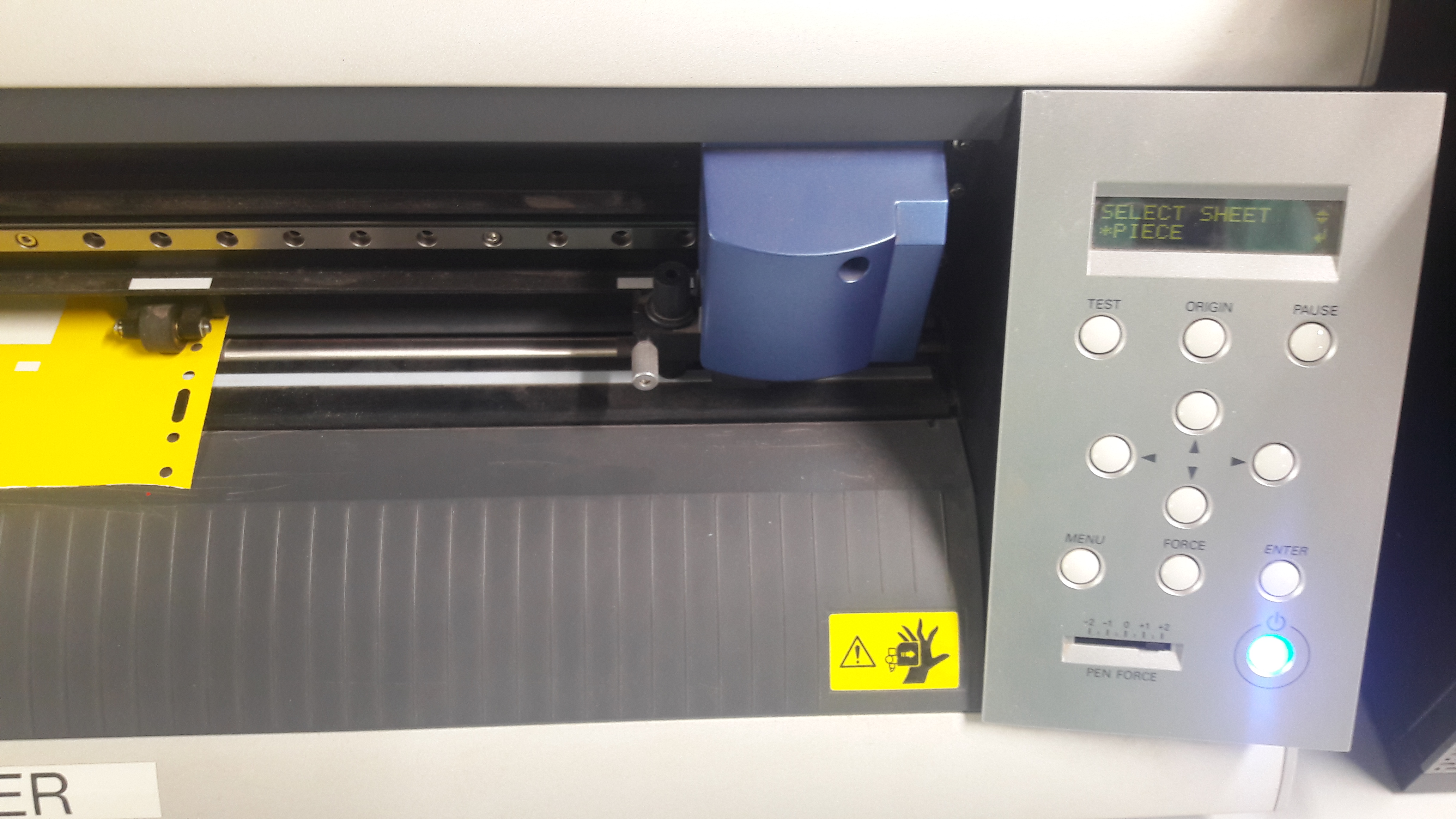
First I used piece for doing a trial run. Due to the small size of the sheet loaded in the machine, attend failed. The machine couldn’t print half of my design.
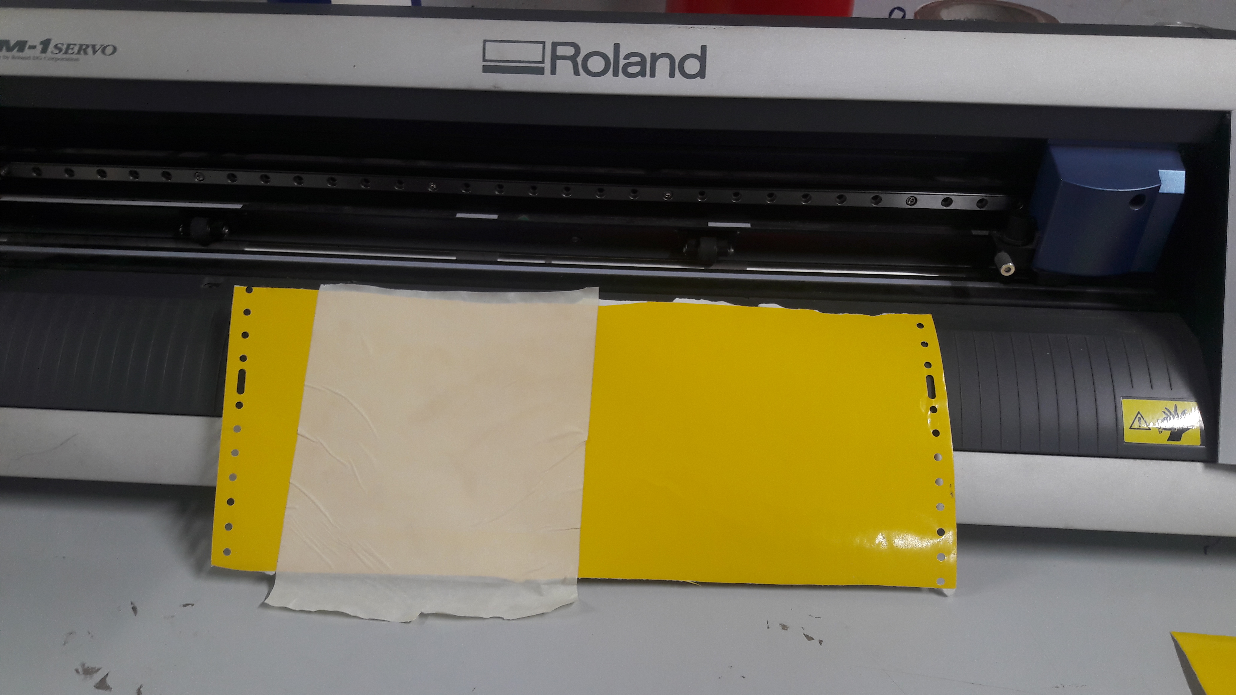
Later I repeated the assignment with proper roll and I could print my work properly.
Getting your sticker:
1. After finishing cutting, take out your piece and Remove the parts you don't need. Actually I forget to do this step.
2. Put the adhesive tape or regular transparent scotch tape on the design to transfer it.so that the design sticks to the tape.
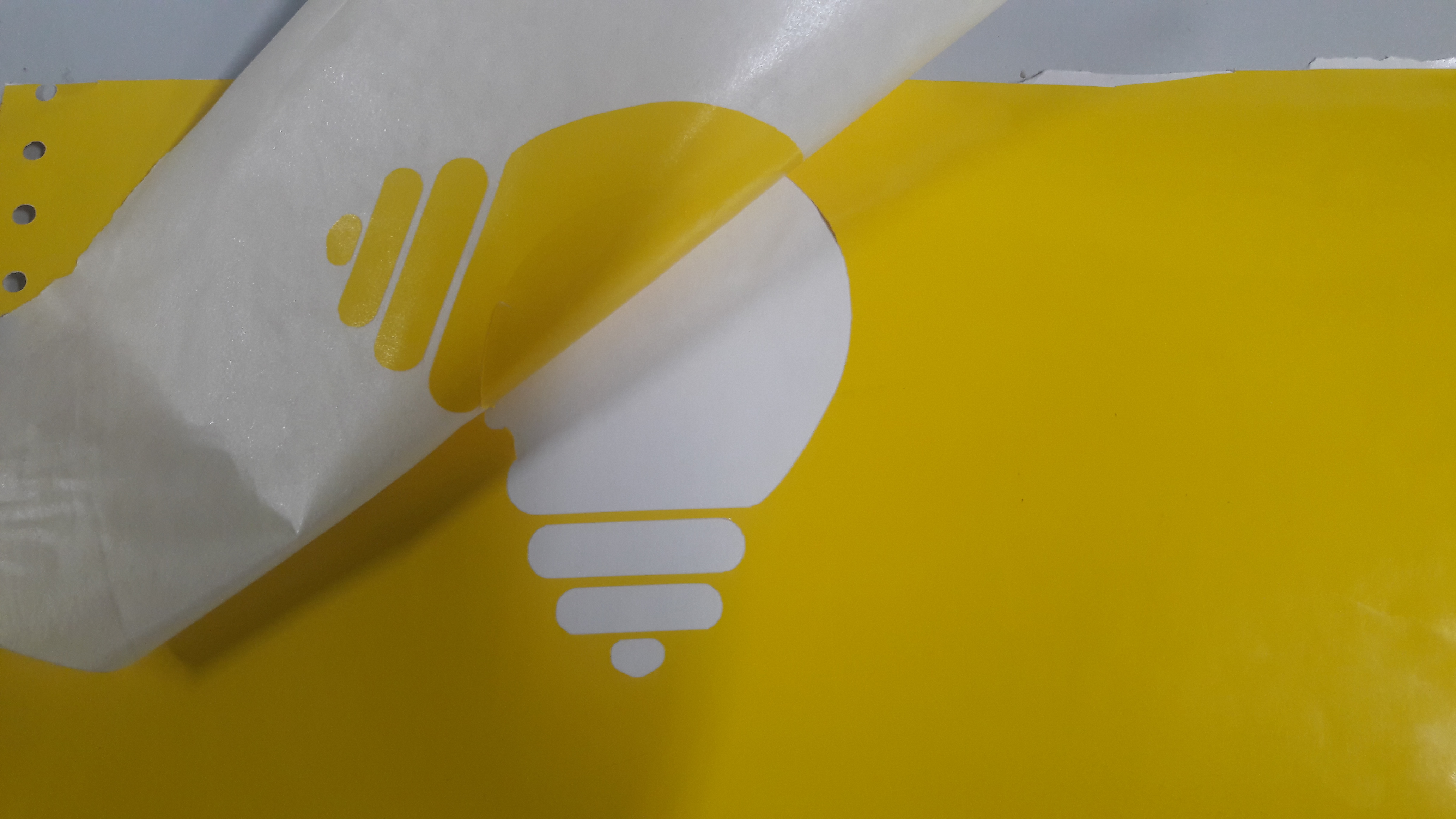
3.3. Now carefully transfer the design to the surface we need.
(Stick the scotch tape in the surface and press it evenly without the formation of air bubble.)
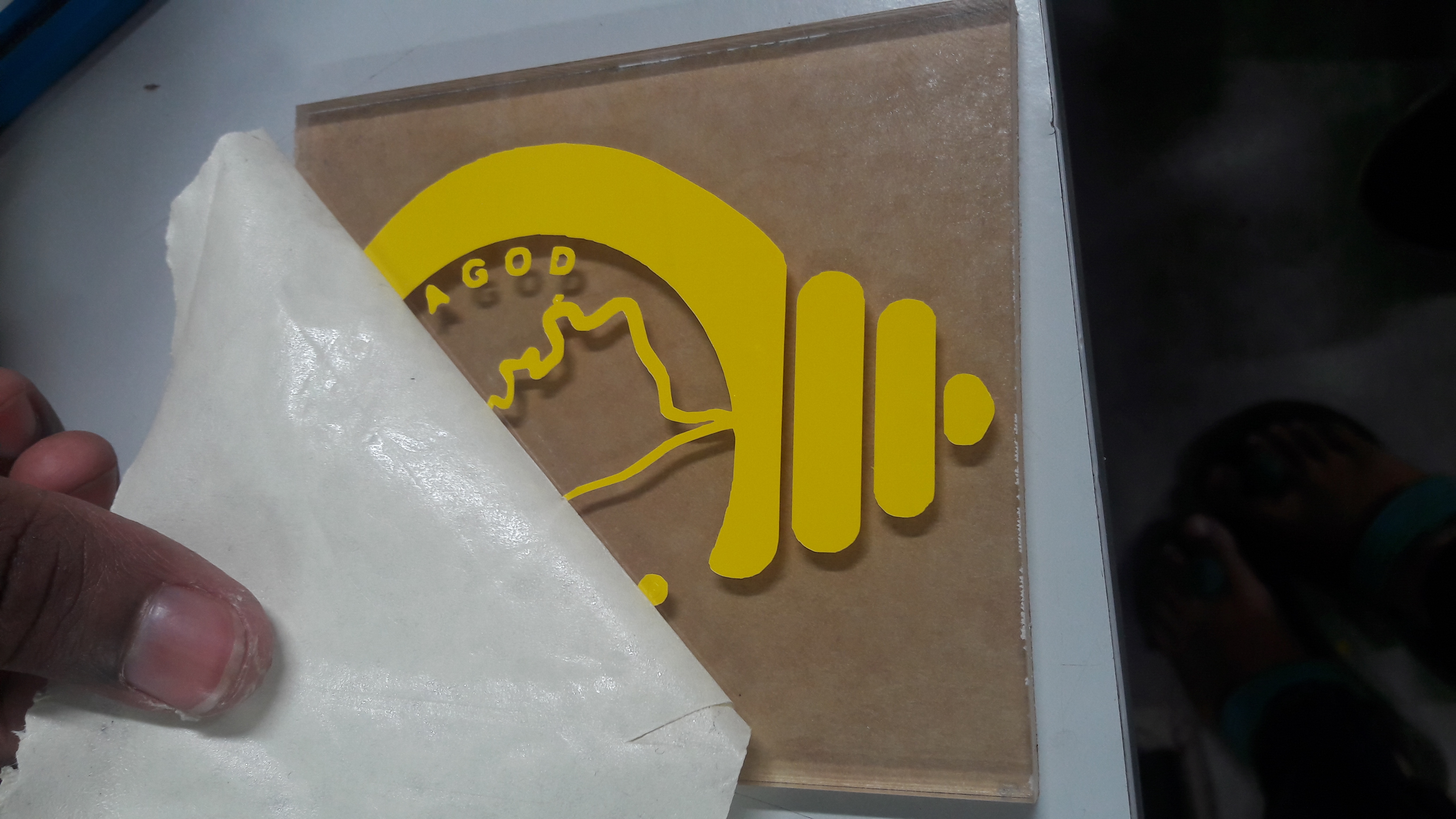
4. Now the design will get stick into the surface. Remove the tape slowly and carefully.
(Use NT cutter if the surface is still not getting detached.)
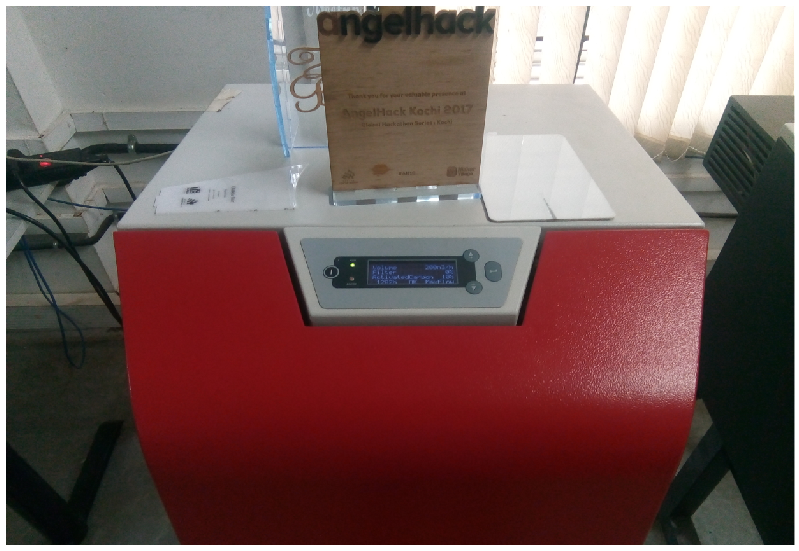
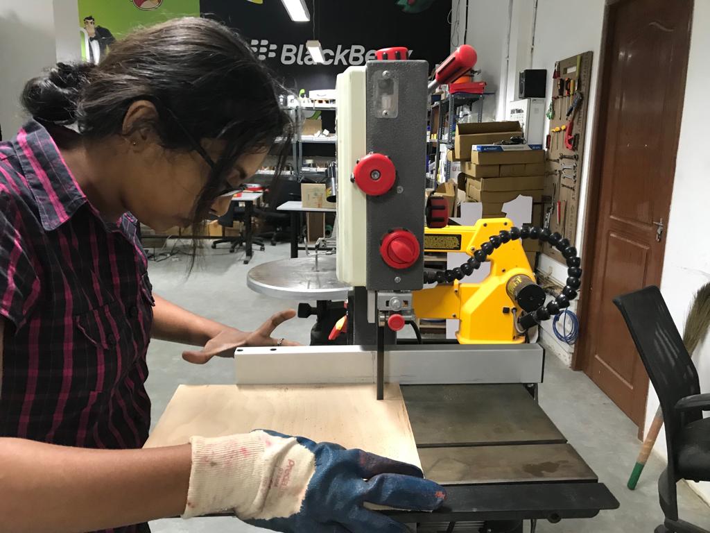
Laser cutter
Laser cutting is a technology that uses a laser to cut materials, and is typically used for industrial manufacturing applications, but is also starting to be used by schools, small businesses, and hobbyists. Laser cutting works by directing the output of a high-power laser most commonly through optics. The laser optics and CNC (computer numerical control) are used to direct the material or the laser beam generated. A typical commercial laser for cutting materials involved a motion control system to follow a CNC or G-code of the pattern to be cut onto the material. The focused laser beam is directed at the material, which then either melts, burns, vaporizes away, or is blown away by a jet of gas, leaving an edge with a high-quality surface finish. Industrial laser cutters are used to cut flat-sheet material as well as structural and piping materials.
Machine details
Filter and ON/OFF switch
Focusing the laser beam
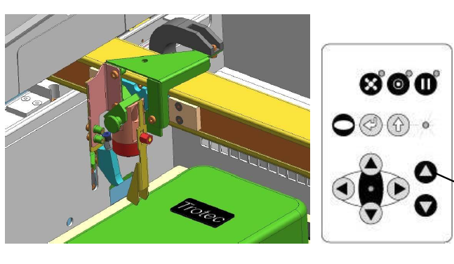
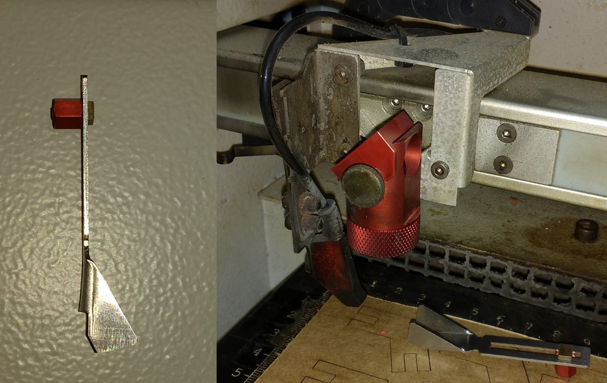
Move the processing head over the material to be engraved by means of the positioning keys X/Y.Hang the focus tool on the external ring of the working head so that the focus tool can move unhindered. Move the working table upwards by pressing the Z positioning key . While doing this carefully observe the focus tool.Before the focus tool reaches the work piece, move the working table upwards only very slowly and step by step by briefly tapping the positioning key, until the tool tilts to the side. Now the lens is focused onto the surface of the material (Source: Users maual.)
Select to print the document(Ctrl + P).Choose "Trotic Engraverv10.4.0" as printer
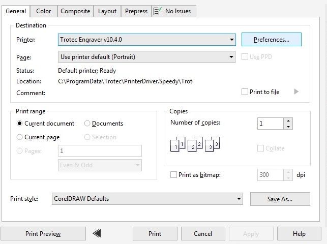
Go to preference -> print -> material Setting -> paper/plastic/wood and their corresponding thickness -> proceed to print.
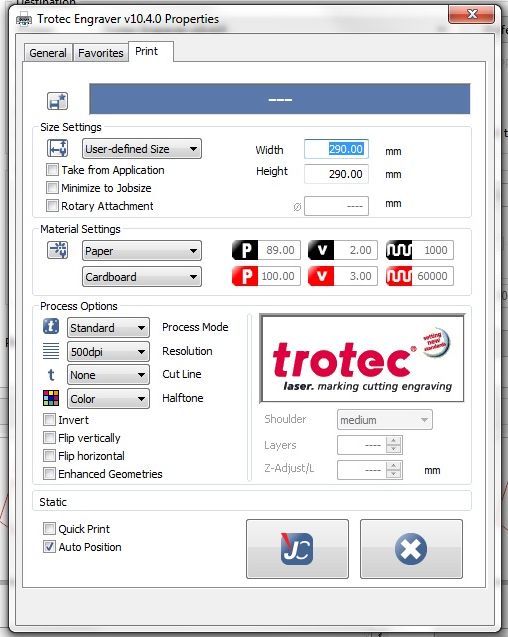
The trotic software will popup .From the list choose our file .Double click on the file and ensure wether the proper file is choosen.
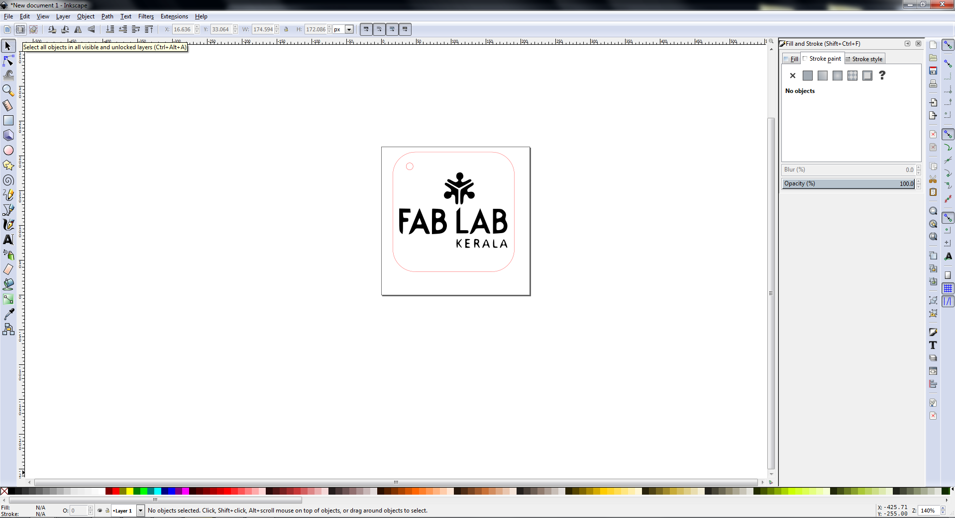
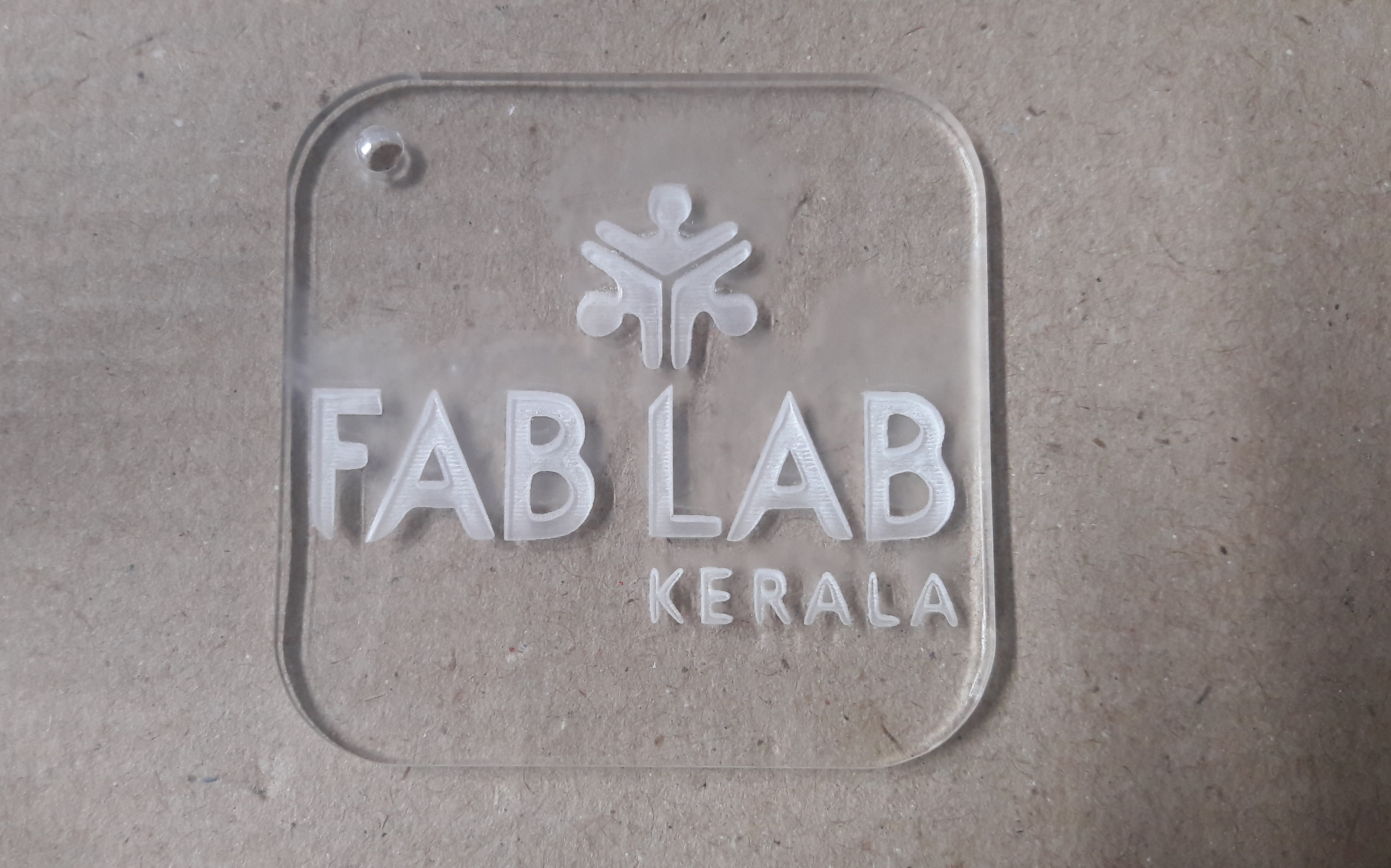
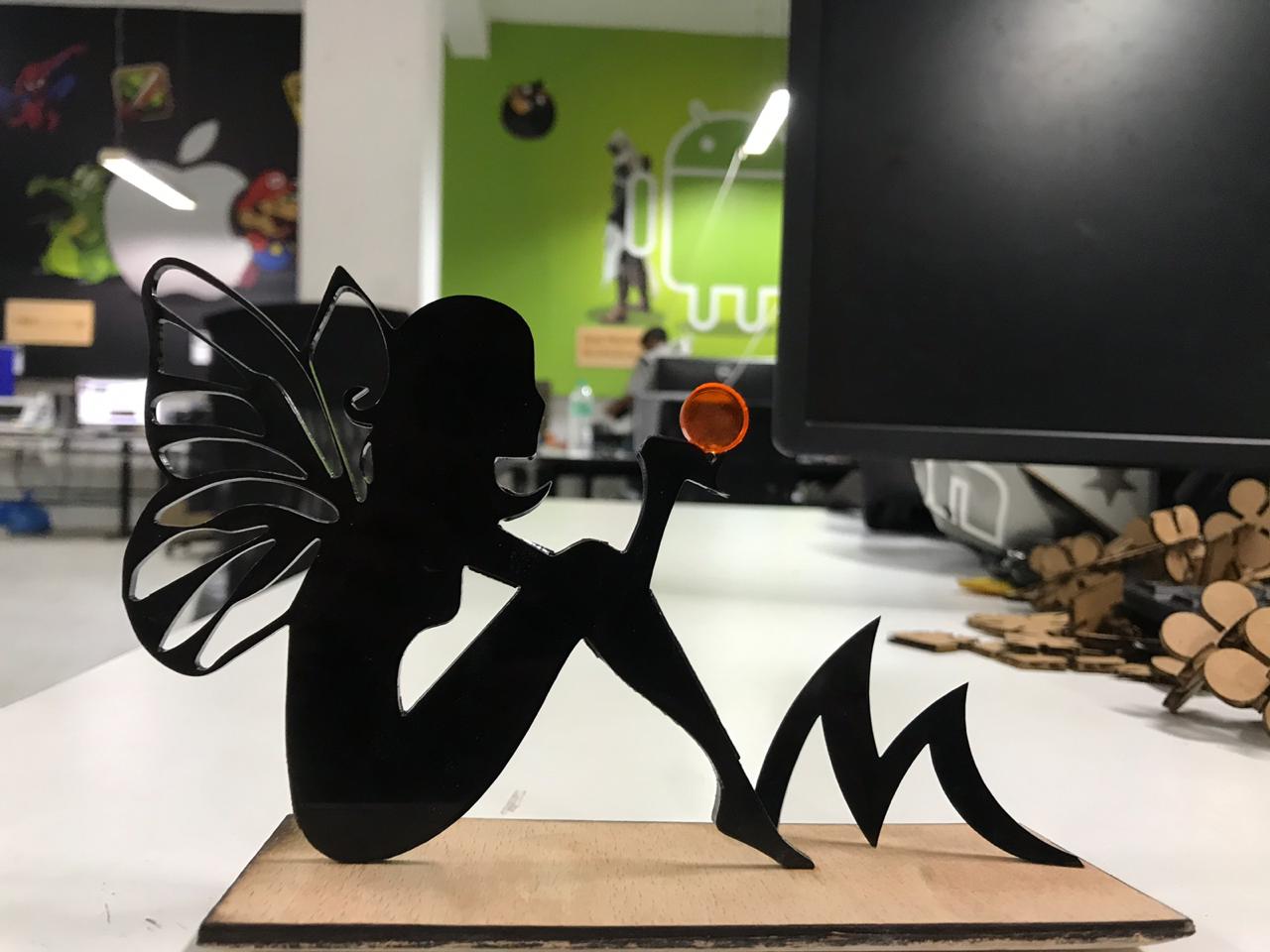
Now the machine is ready to do any work. I want to take a test drive with my fab lab kerala logo. So I have made a key chain. For that I load the image into inkscape and took it's bitmap. For cutting into a key chain, I drew a rectangle around it and colour it outline as red. Now add a circle for the hole and press print.
When print option is given, Trotec laser driver software comes online. First I set red to cut and black to engrave. Then I selected material and thickness.
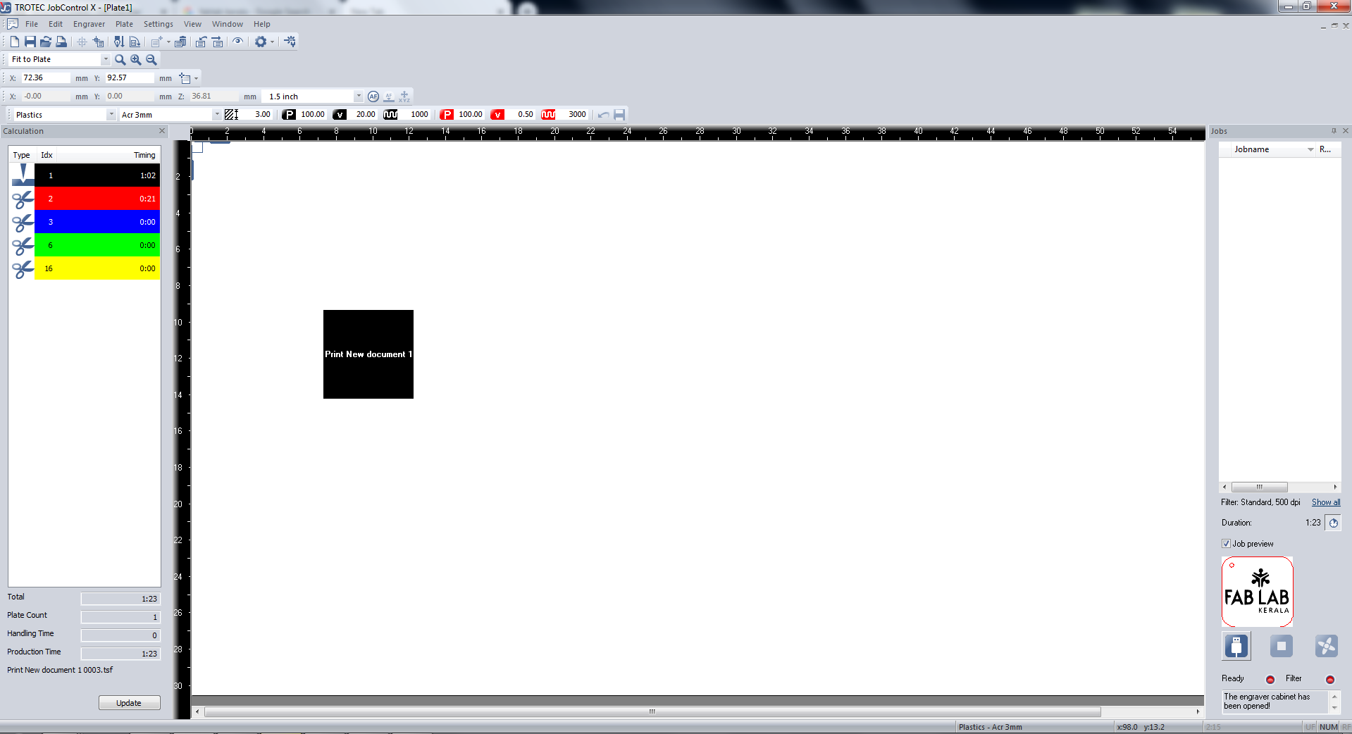
now postion the laser where to start cut and aline the job in the window like below and press ready.
You can download the inkscape file from here.
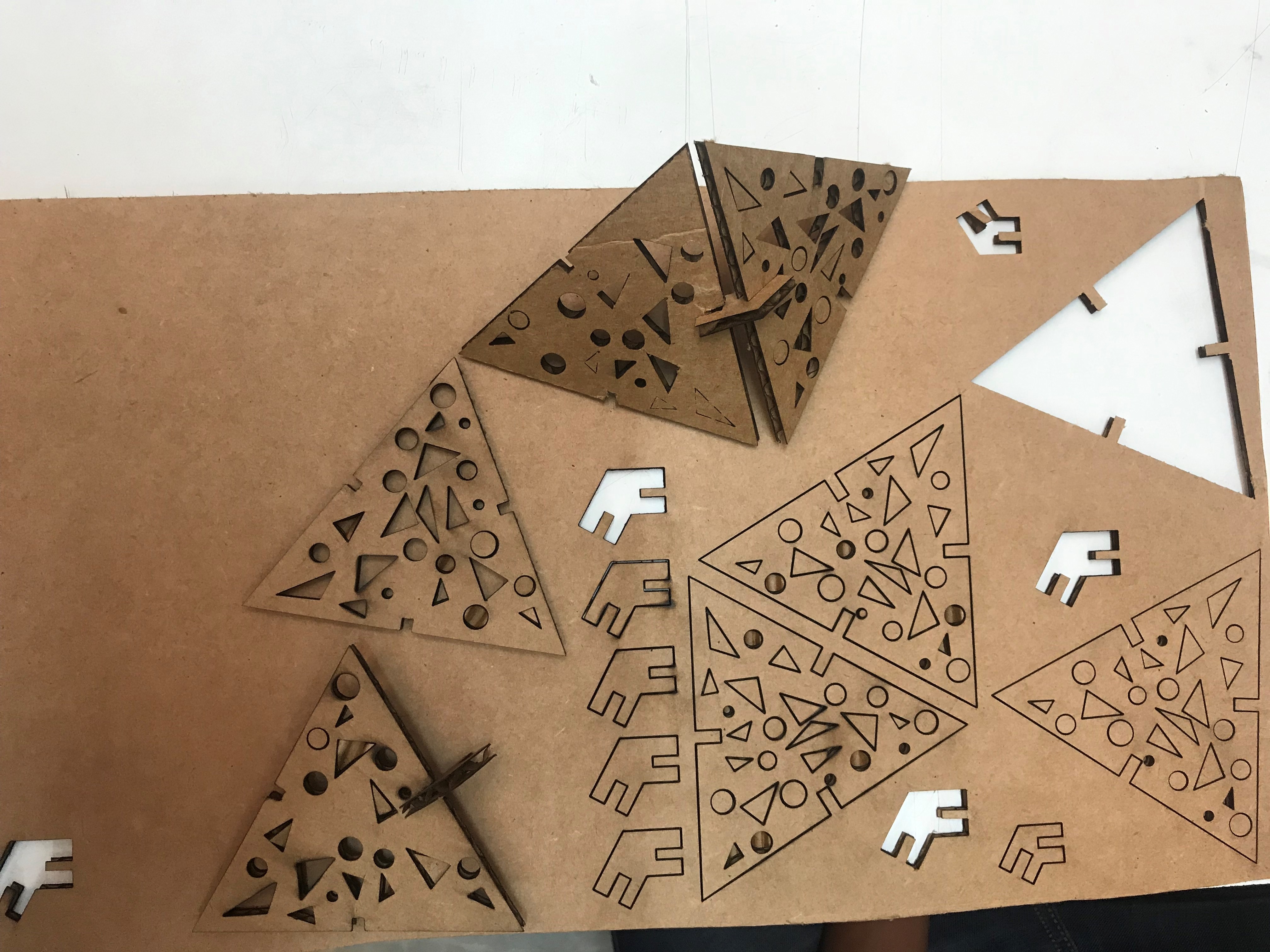
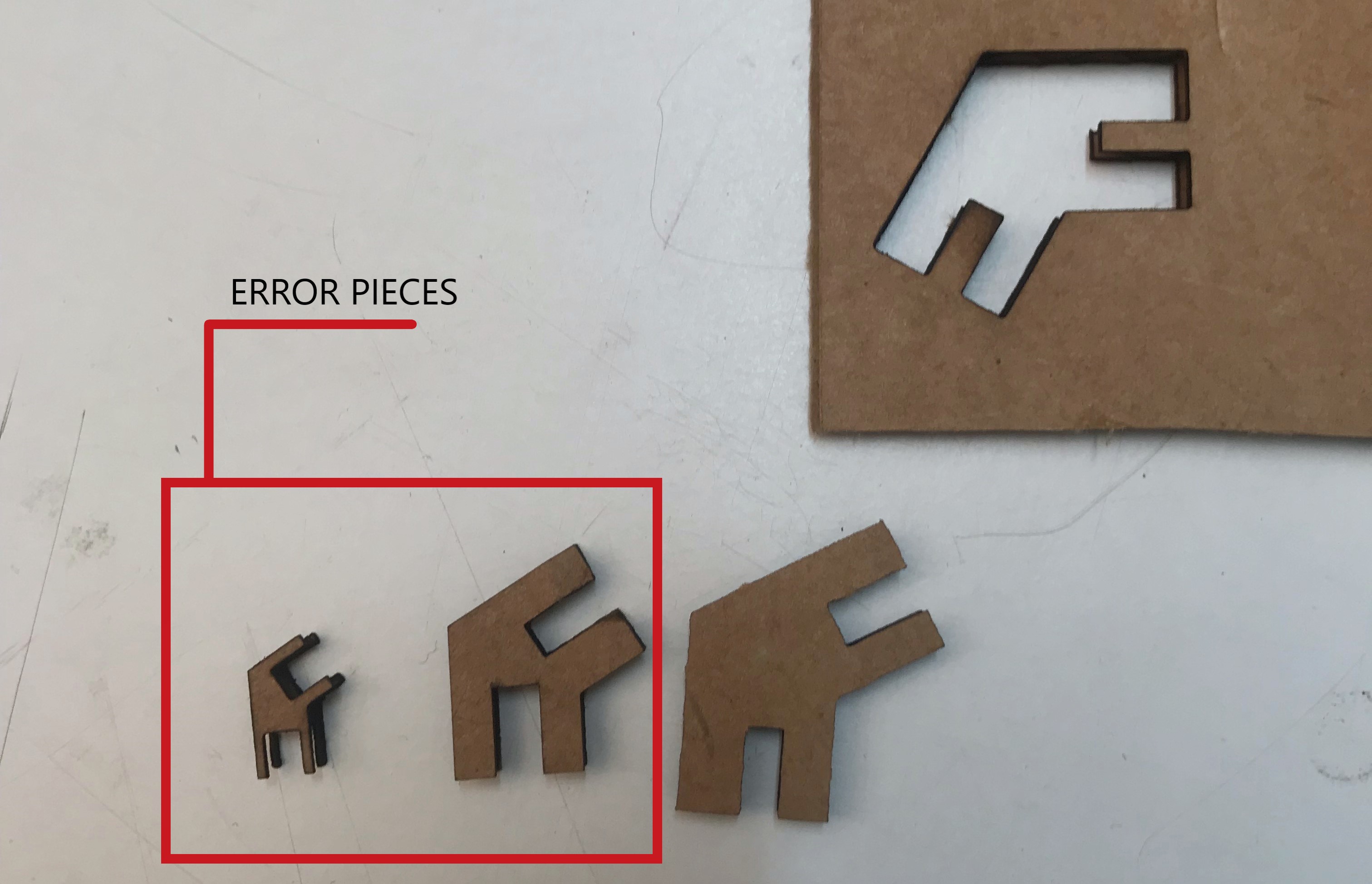
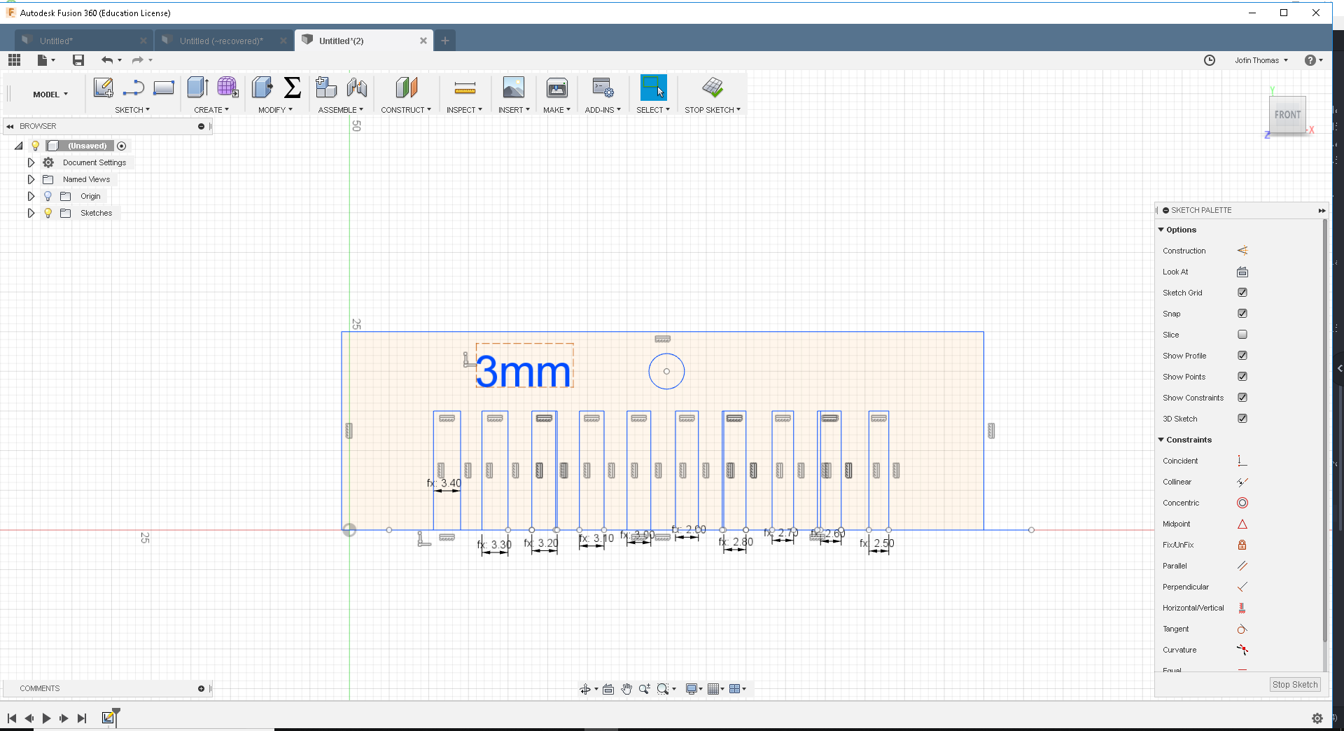
Parametric Press-Fit design
The main assignment for this week was to create a parametric press fit design.In parametric design each measurement is related to other values with some kind of equations. So that when we change one, the rest changes automatically. Parametric designing makes our project easily editable. In case of our press fit design, we can always use different materials ranging from cardboard pieces to acrylic and each of them has different thickness and kerf values. So redesigning every value for different materials is a difficult task. But in parametric design, all you have to do is to change the thickness value according to your materials and rest of the values automatically adjusts to this.
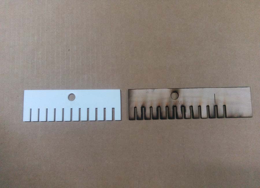
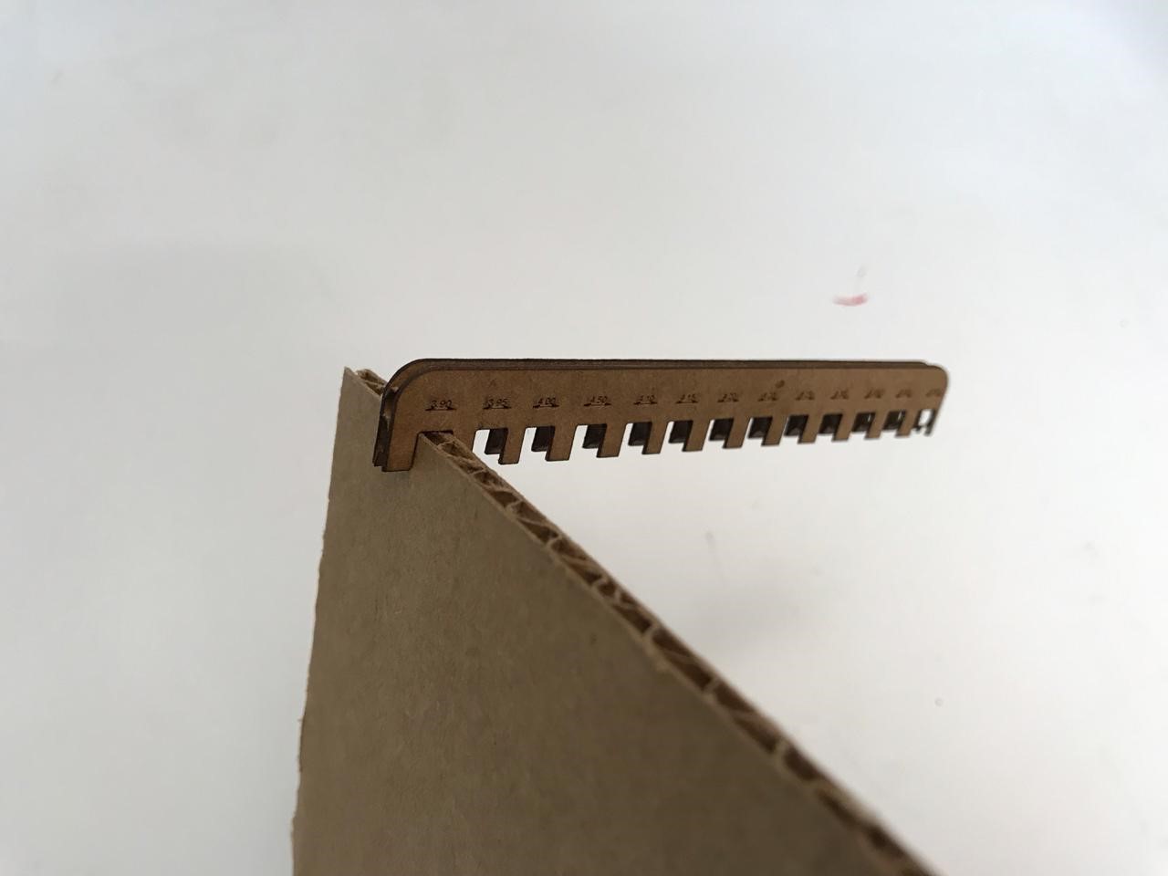
I designed a scale and print it using laser cutter for checking the pressfit.
Kerf Scale
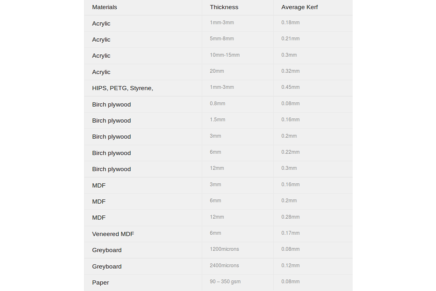
The laser burns away a portion of material when it cuts through. This is known as the laser kerf and ranges from 0.08mm – 1mm depending on the material type and other conditional factors.
Kerf is determined by material properties and thickness. But other factors also have an impact on how much the laser takes away. The focal length of the lens, pressure of compressed air both have an impact. Kerf widths can vary even on the same material sheet, whether cutting a straight line or a curve line or from laser cutting in the x or Y dimension. The manufacturing tolerance of the material can also impact the kerf.
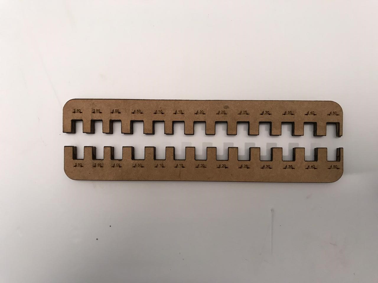
It got pressfit on 3.9 scale, that means the kerf value is .1 mm.therefor the design parameter can be designed using the kerf value .1 mm.
Design
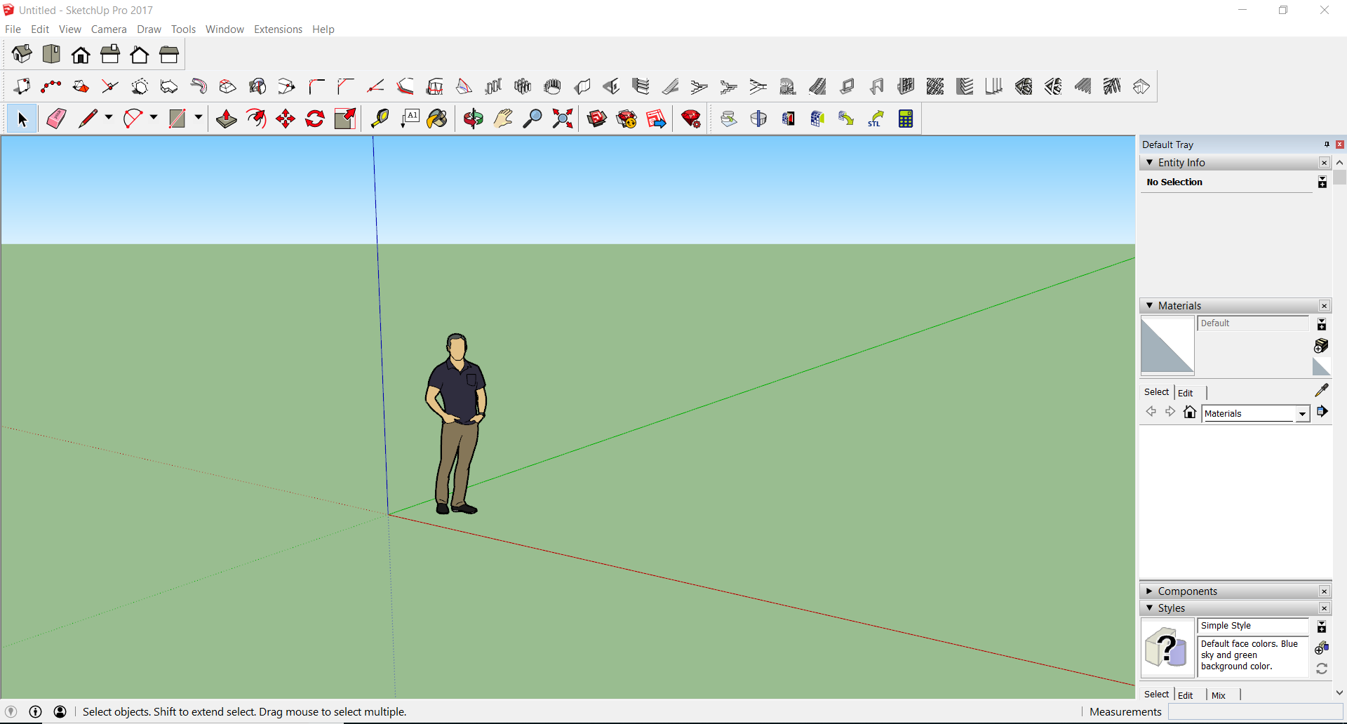
The software i used for designing the model is sketchup pro 2017.
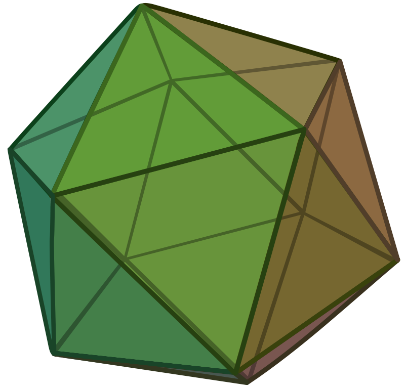
In geometry, an icosahedron is a polyhedron with 20 faces
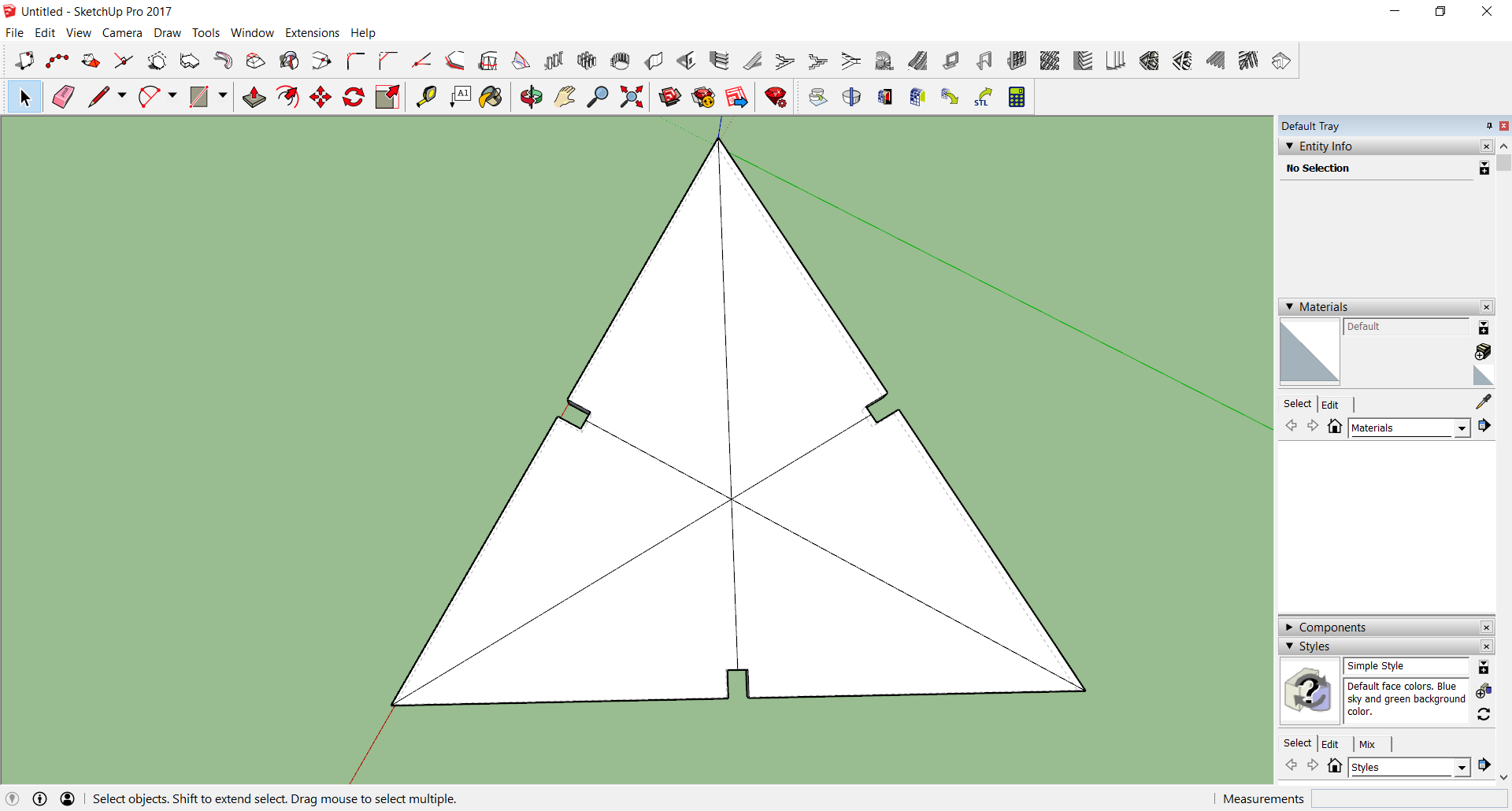
I made the basic triangular unit first.
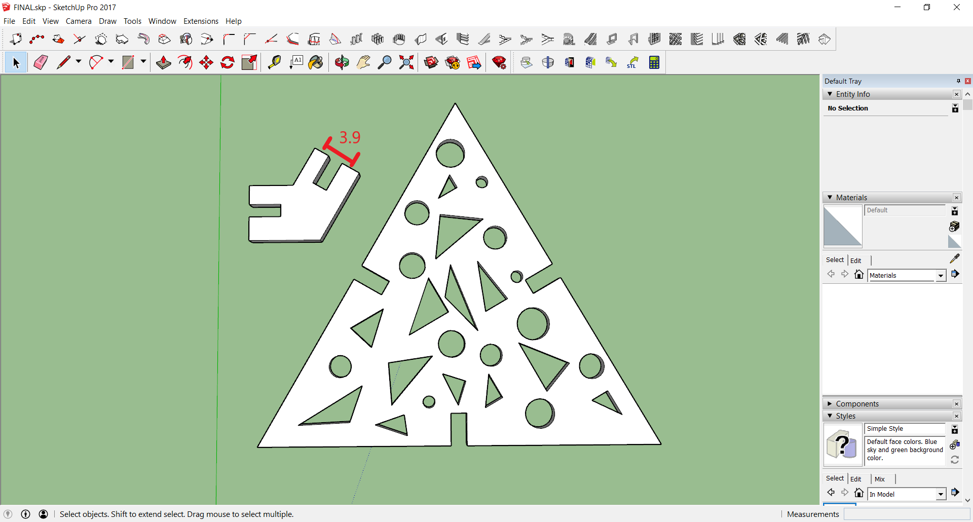
The angle of joint is 138
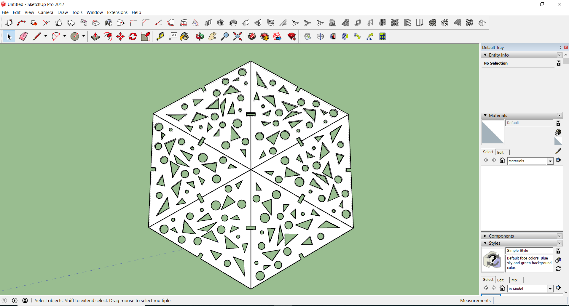
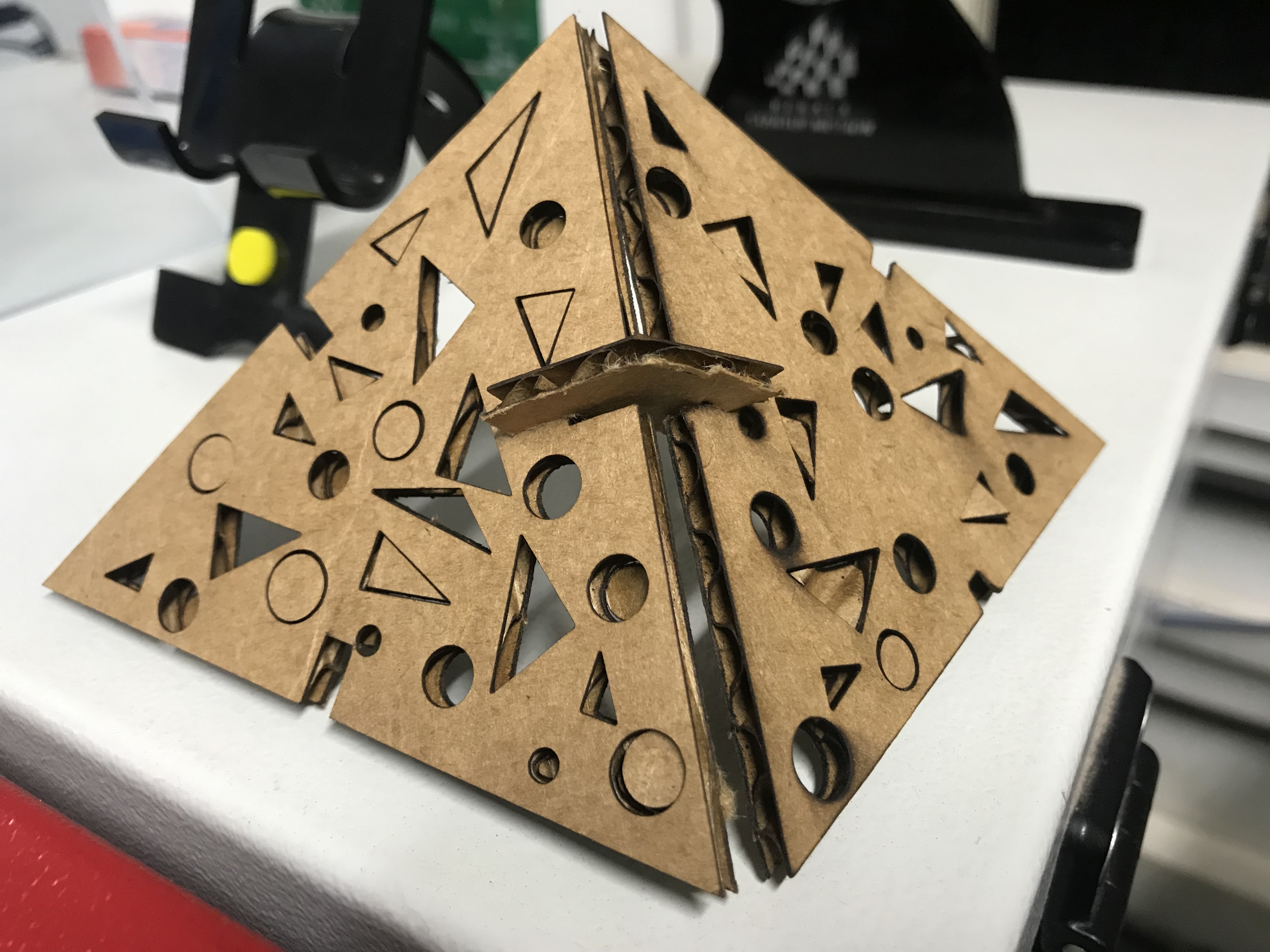
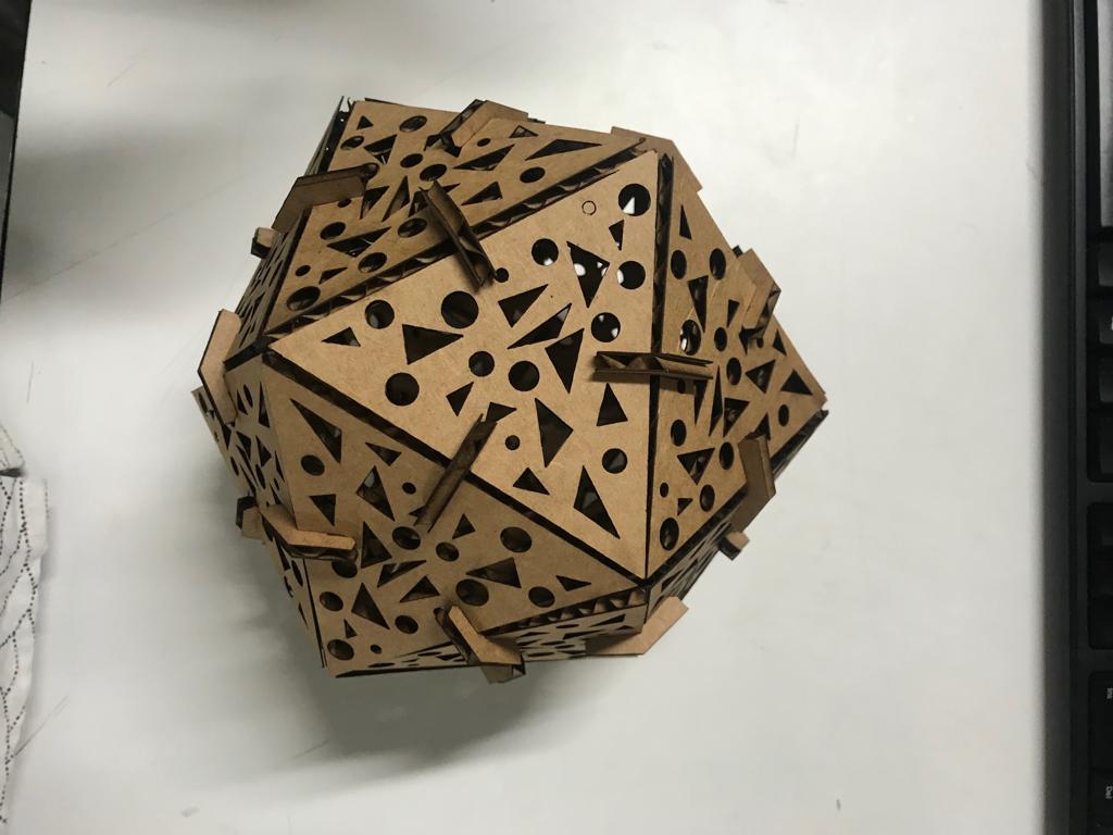
The convex regular icosahedron is usually referred to simply as the regular icosahedron, one of the five regular Platonic solids, and is represented by its 20 triangular faces, with 5 faces meeting around each vertex.
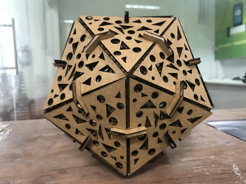
You can download the whole project from here.
EXPERIMENTING
Group Assignment
This week we got our first group assignment.
Characterize your lasercutter, making test part(s) that vary cutting settings and dimensions
As part of testing out the laser cutter we had made a Kerf Scale. Kerf is simply the amount of materilal removed during the cutting process.The different kerf scales is as follows.
So we designed a scale and print it using laser cutter
Cutting Parameters
Power - 75
Velocity - .90
Freq - 7000
Engraving Parameters
Power - 75
Velocity - 90
Freq - 500
Kerf Scale