
Individual assignment: Add an output device to a microcontroller board you've designed, and program it to do something
Group assignment: Measure the power consumption of an output device
.
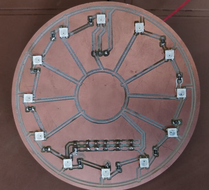
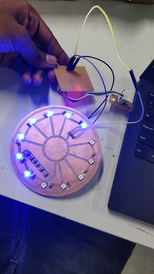
In this week i was hoping to do a neopixel ring which could be added to my clock from Week 8 - computer comtrolled cutting.The same board atmega 328p board from week 11 could be used for this neo pixel ring
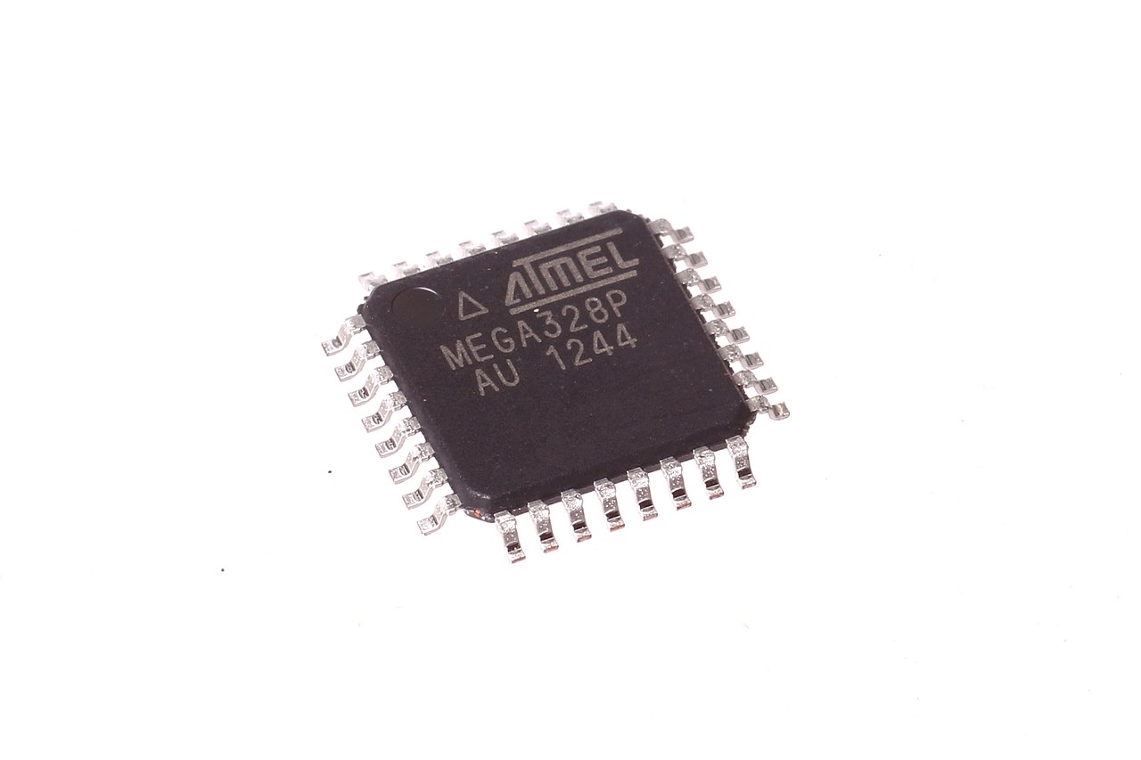
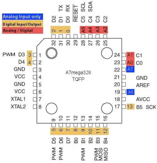
The ATmega328 is a single-chip microcontroller created by Atmel in the megaAVR family (later Microchip Technology acquired Atmel in 2016). It has a modified Harvard architecture 8-bit RISC processor core.The Atmel 8-bit AVR RISC-based microcontroller combines 32 kB ISP flash memory with read-while-write capabilities, 1 kB EEPROM, 2 kB SRAM, 23 general purpose I/O lines, 32 general purpose working registers, three flexible timer/counters with compare modes, internal and external interrupts, serial programmable USART, a byte-oriented 2-wire serial interface, SPI serial port, 6-channel 10-bit A/D converter (8-channels in TQFP and QFN/MLF packages), programmable watchdog timer with internal oscillator, and five software selectable power saving modes. The device operates between 1.8-5.5 volts. The device achieves throughput approaching 1 MIPS per MHz.
.
.
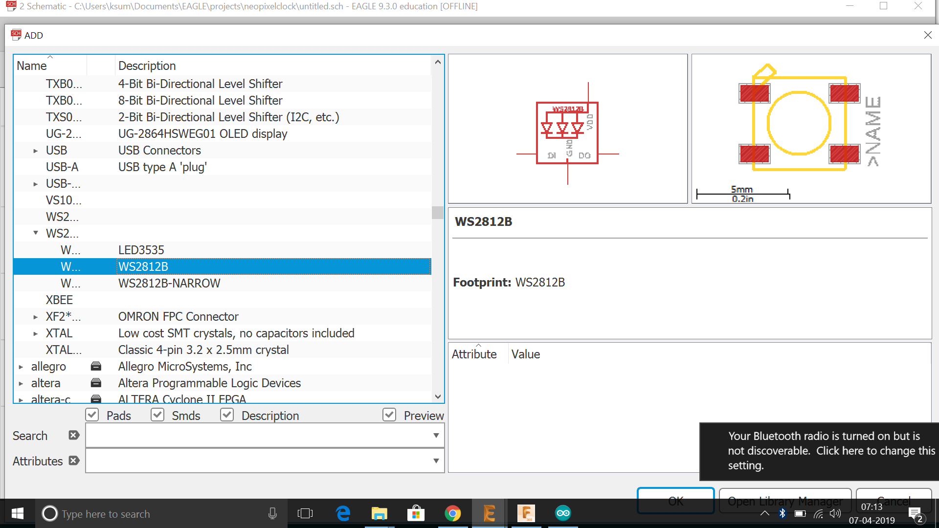
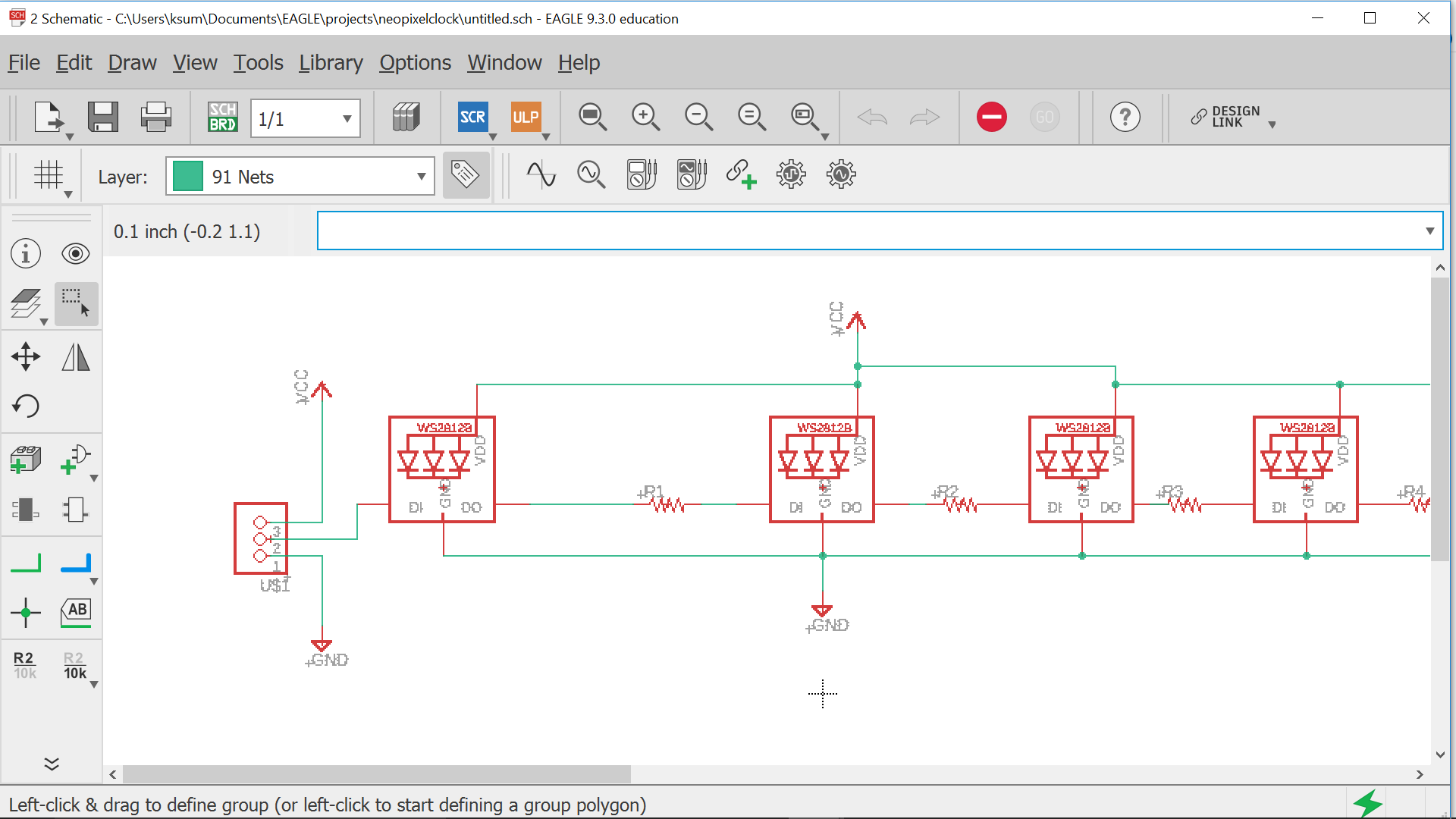
WS2812B is a intelligent control LED light source that the control circuit and RGB chip are integrated in a package of 5050 components. It internal include intelligent digital port data latch and signal reshaping ampli fication drive circuit. Also include a precision internal oscillator and a 12V voltage programmable constant curr e-nt control part, effectively ensuring the pixel point light color height consistent.
.
.
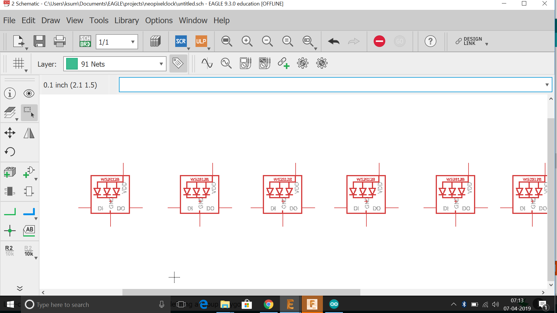
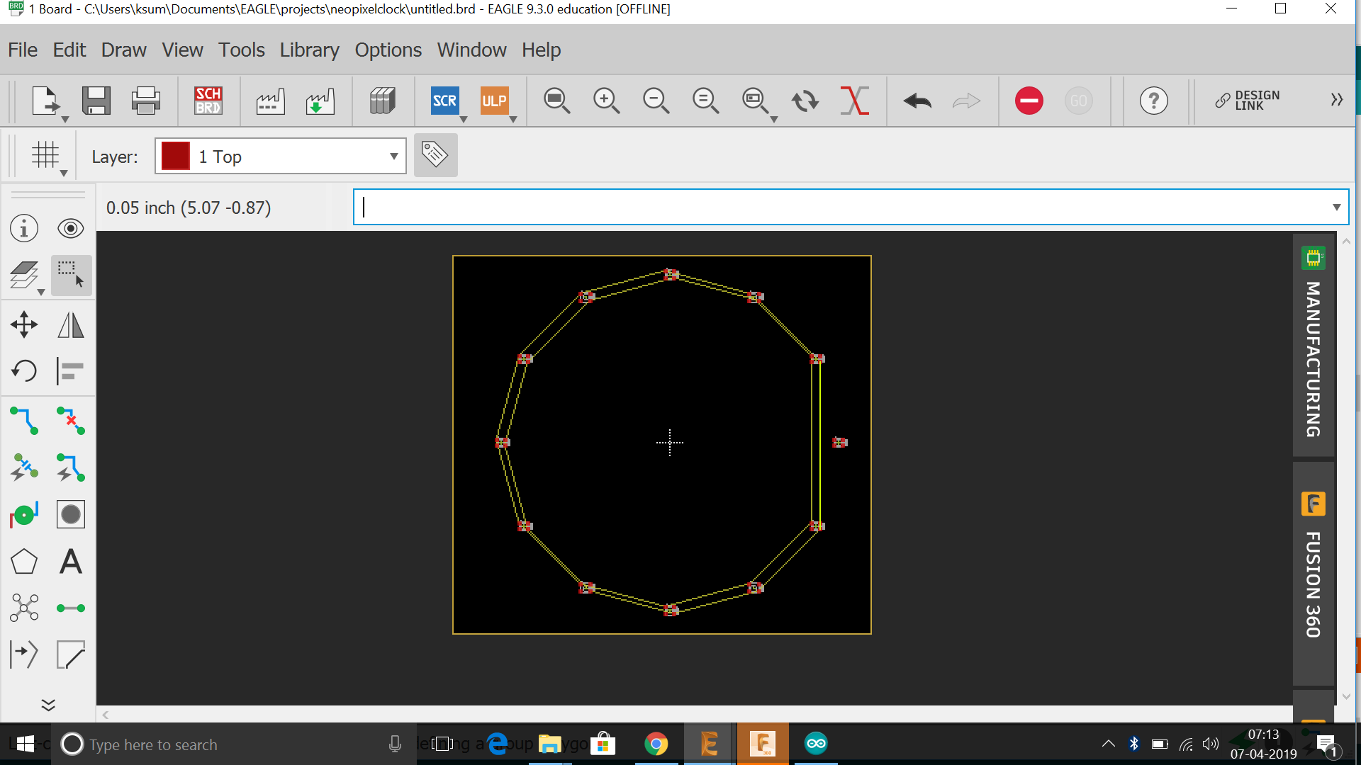
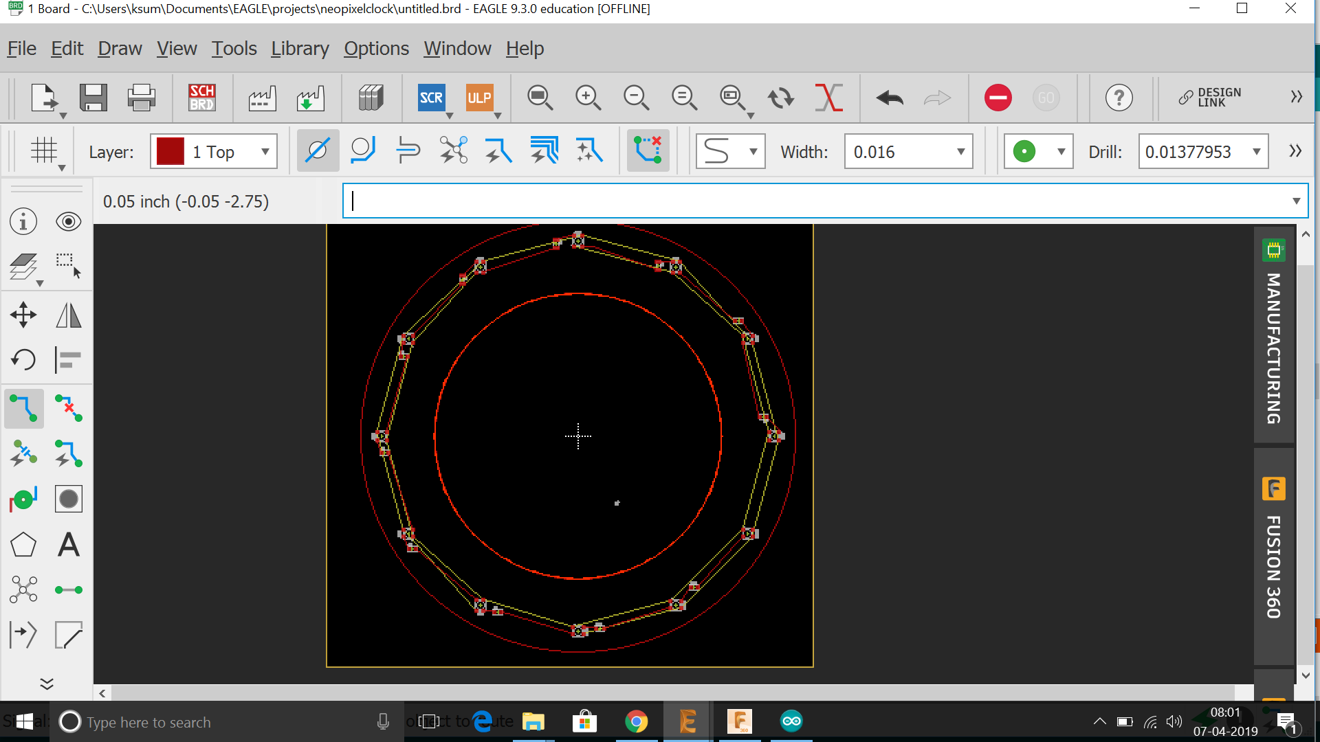
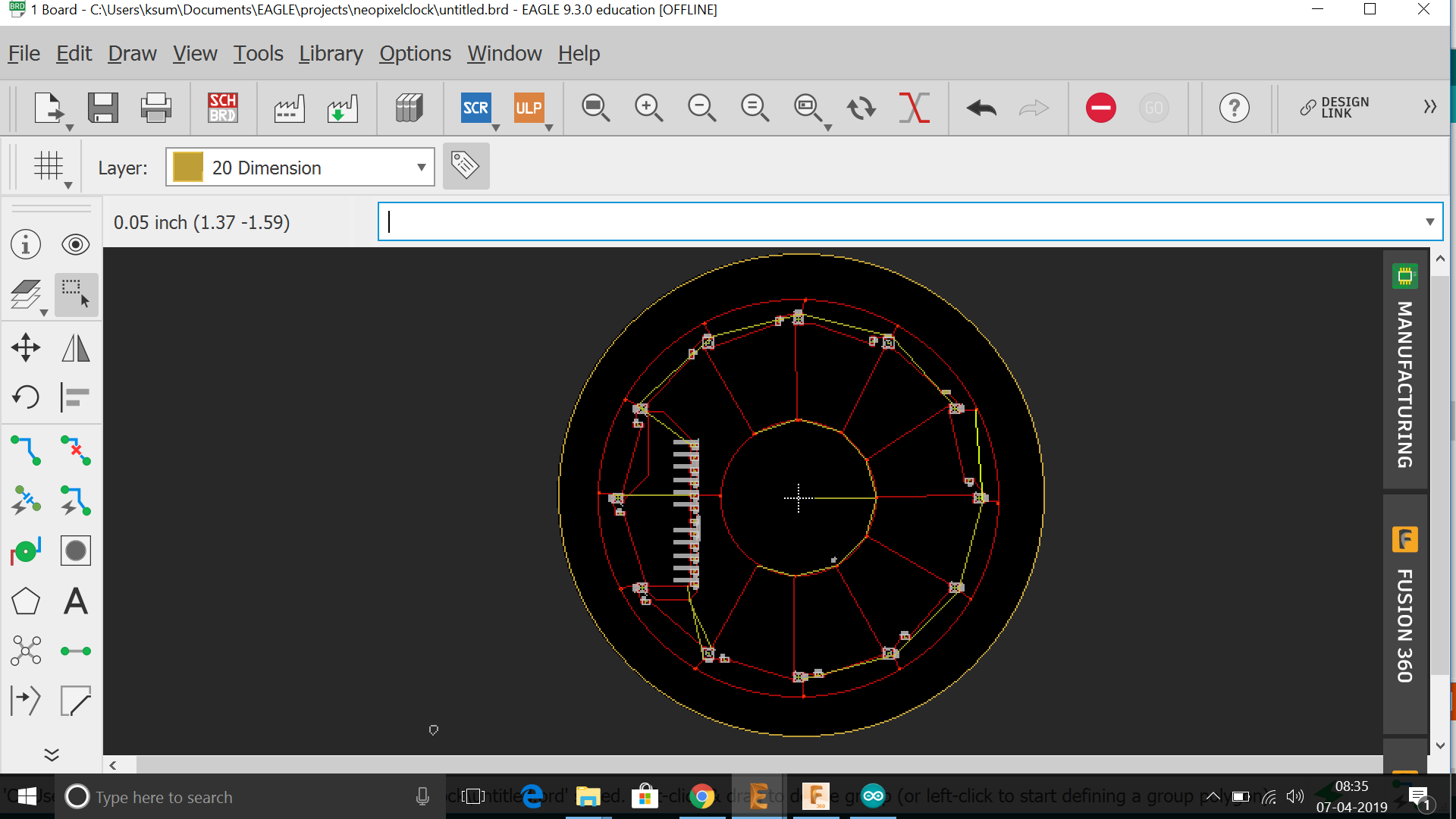
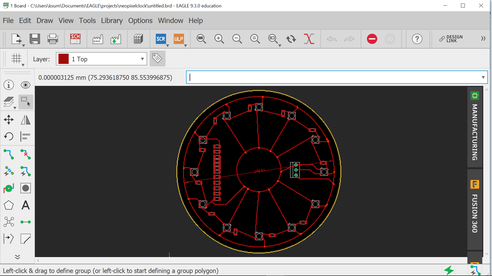
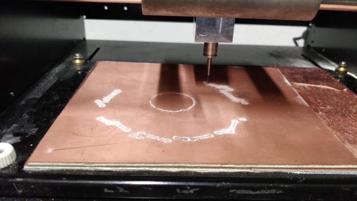
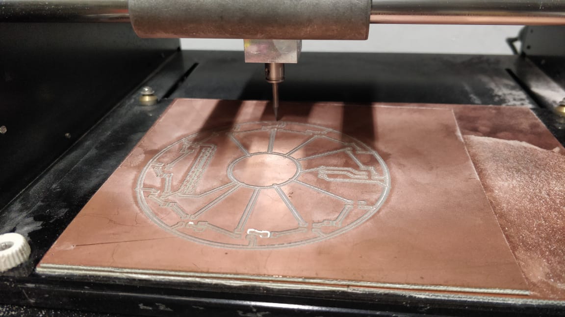
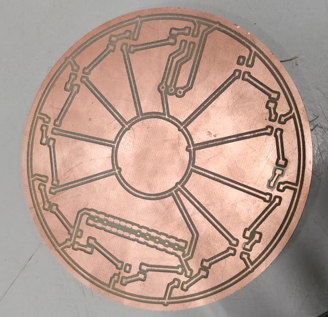
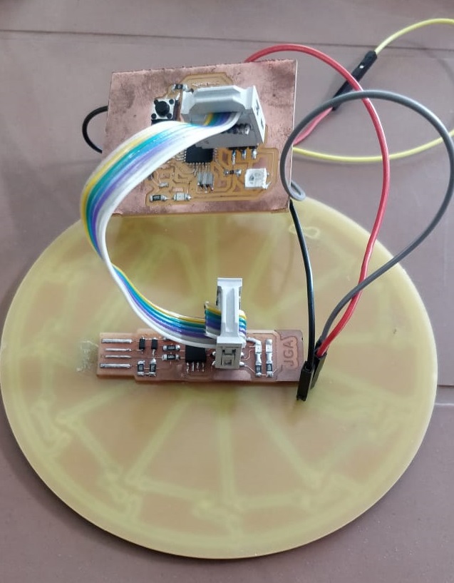
Since i had already done a board for controlling the neopixel led in week11 usinf atmega328p , i thought i would extend the same to this week by making another board to coonect with the same.
.
.
.
.
.
.
.
.
.
.
.
.
.
.
.
.
.
.
.
.
.
.
.
.
.
.
.
.
.
.
.
.
.
.
.
.
.
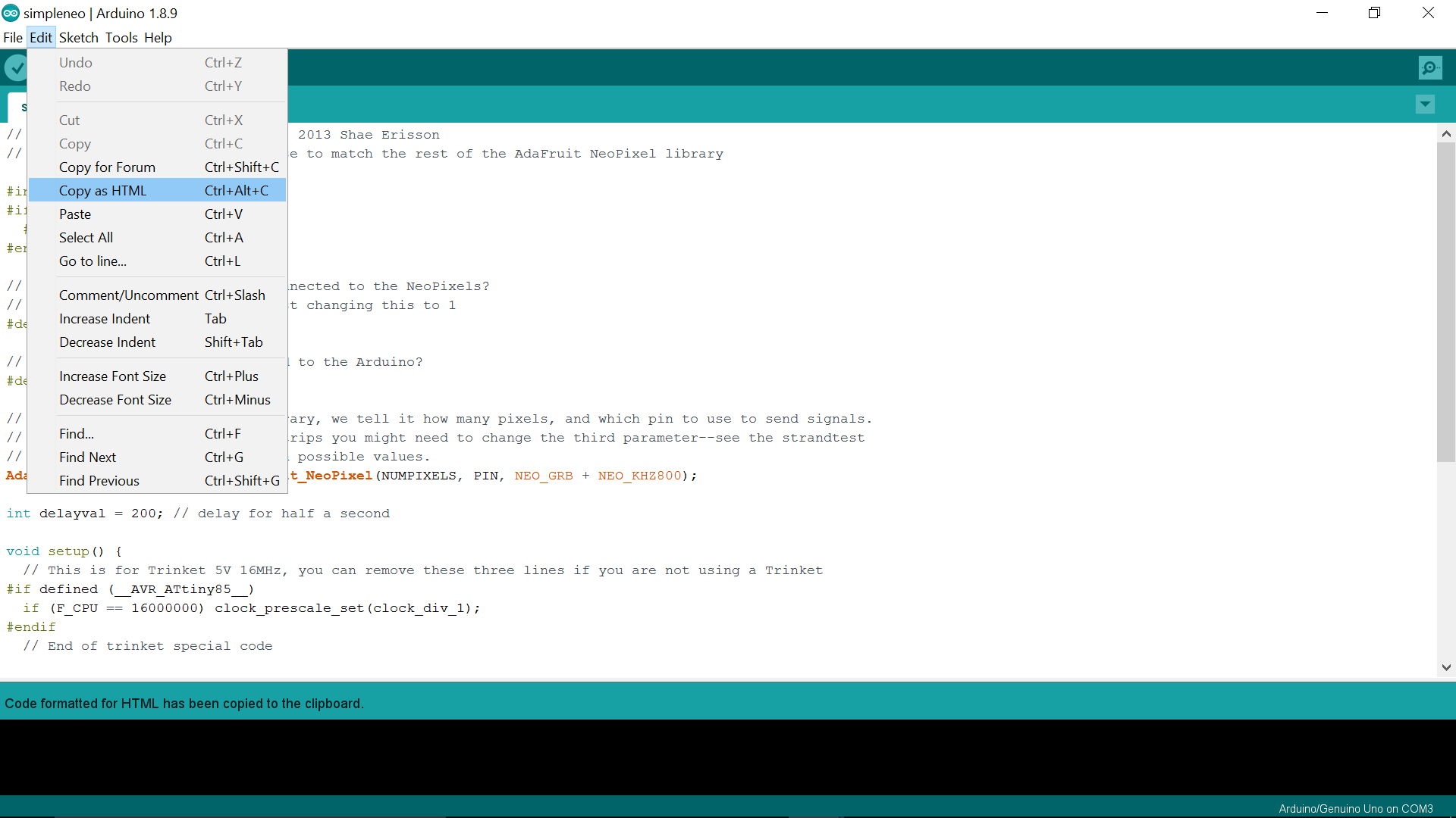
Next step is to program the neopixel board with atmega 328p microcontroller board which i had made on last week
.
.
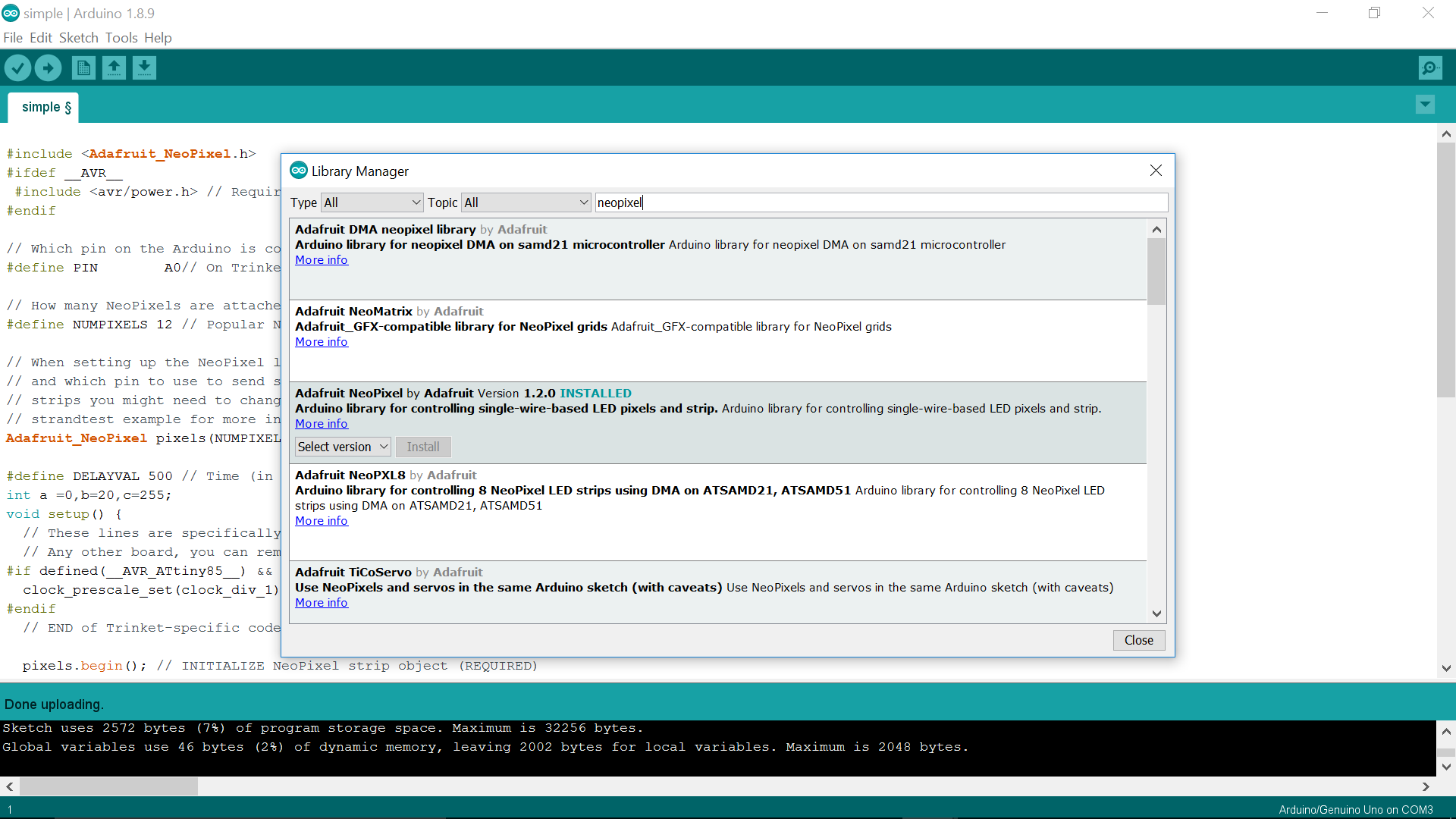
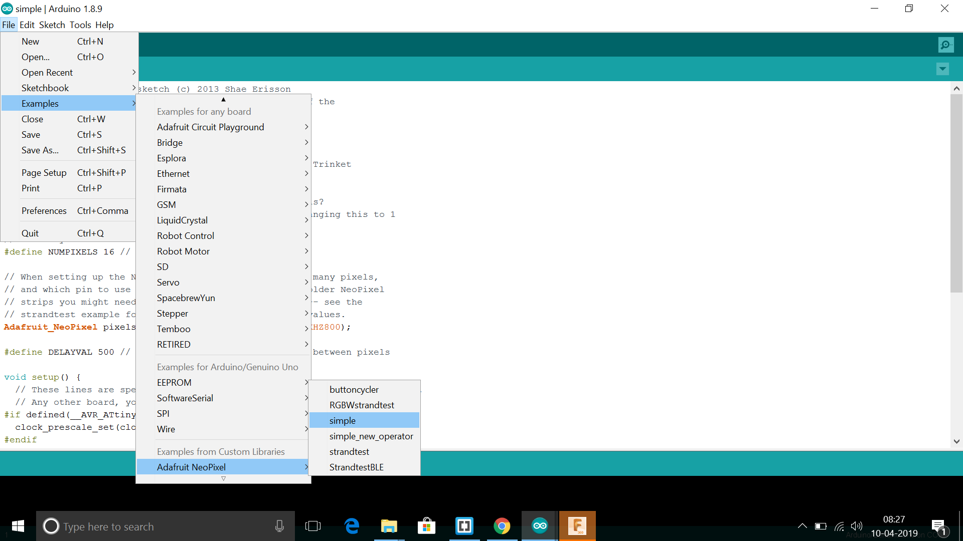
The neopixel library for arduino was downloaded from library manager. Select Tools -> Manage library. Search for neopixel library and install the same as shown below
.
.
.
.
.
.
.
.
.
.
.
.
#include <Adafruit_NeoPixel.h>
#ifdef __AVR__
#include <avr/power.h> // Required for 16 MHz Adafruit Trinket
#endif
// Which pin on the Arduino is connected to the NeoPixels?
#define PIN A0// On Trinket or Gemma, suggest changing this to 1
// How many NeoPixels are attached to the Arduino?
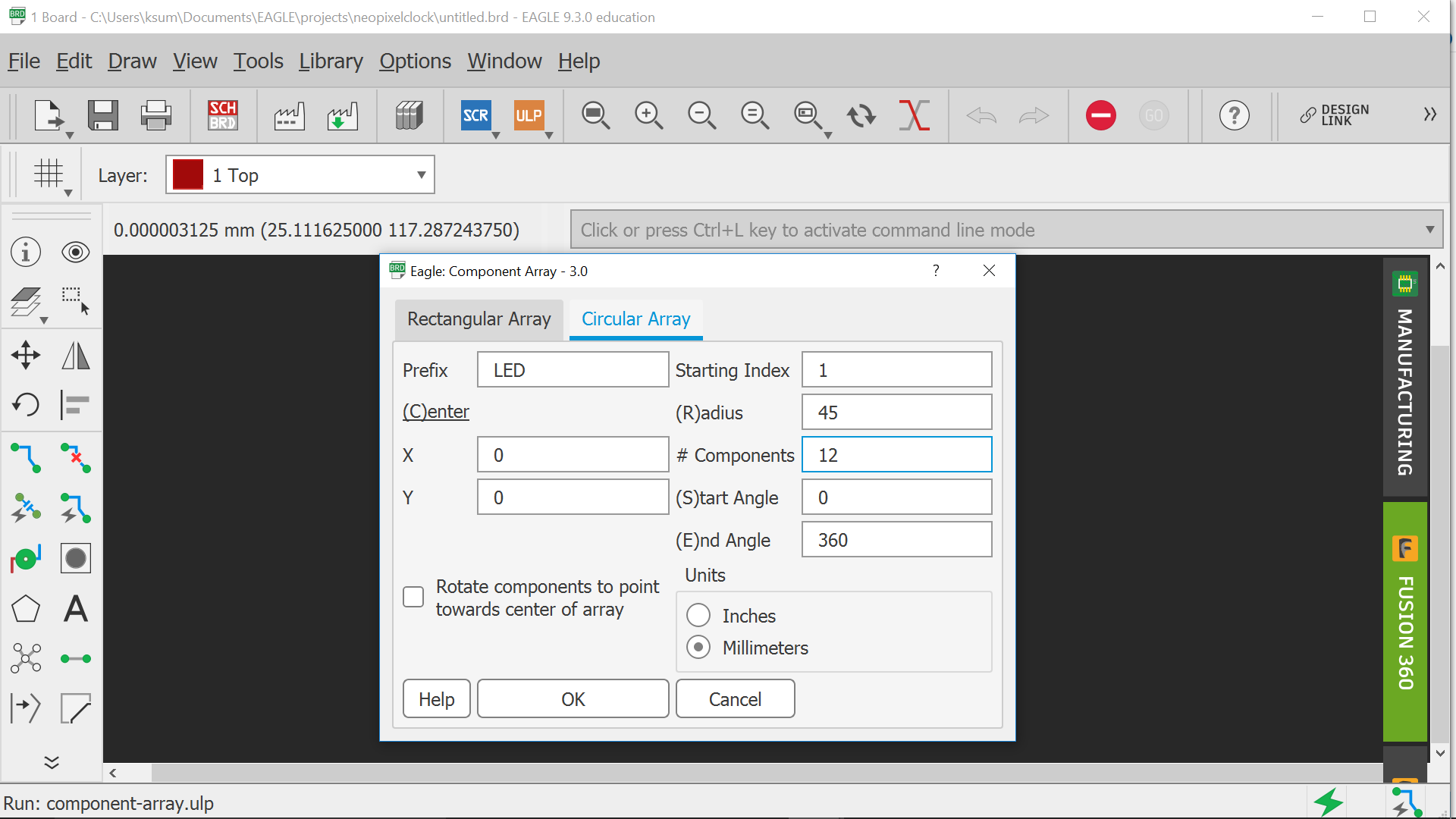
#define NUMPIXELS 12 // Popular NeoPixel ring size
// When setting up the NeoPixel library, we tell it how many pixels,
// and which pin to use to send signals. Note that for older NeoPixel
// strips you might need to change the third parameter -- see the
// strandtest example for more information on possible values.
Adafruit_NeoPixel pixels(NUMPIXELS, PIN, NEO_GRB + NEO_KHZ800);
#define DELAYVAL 500 // Time (in milliseconds) to pause between pixels
int a =0,b=20,c=255;
void setup() {
// These lines are specifically to support the Adafruit Trinket 5V 16 MHz.
// Any other board, you can remove this part (but no harm leaving it):
#if defined(__AVR_ATtiny85__) && (F_CPU == 16000000)
clock_prescale_set(clock_div_1);
#endif
// END of Trinket-specific code.
pixels.begin(); // INITIALIZE NeoPixel strip object (REQUIRED)
}
void loop() {
pixels.clear(); // Set all pixel colors to 'off'
// The first NeoPixel in a strand is #0, second is 1, all the way up
// to the count of pixels minus one.
for(int i=0; i<NUMPIXELS; i++) { // For each pixel...
// pixels.Color() takes RGB values, from 0,0,0 up to 255,255,255
// Here we're using a moderately bright green color:
pixels.setPixelColor(i, pixels.Color(a, b, c));
pixels.show(); // Send the updated pixel colors to the hardware.
delay(DELAYVAL); // Pause before next pass through loop
}
a=a+50;
b=b+50;
c=c-50 ;
if(a==255)
{a=0;}
if(b==255)
{
b=50;}
if(c==0)
{
c=255;}
}
.
.
.
.
.
.
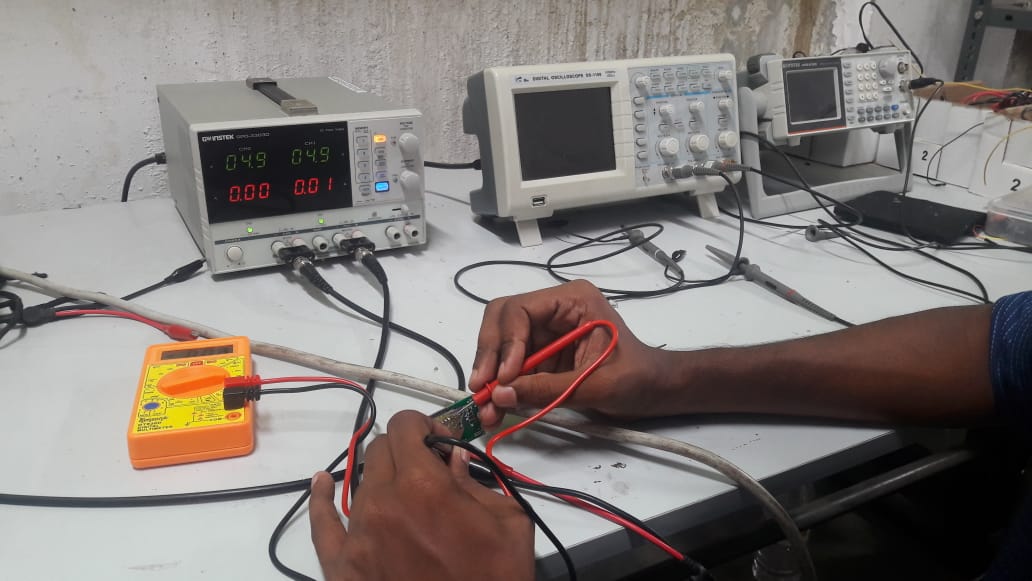
This week group assignment was to measure power consumption of an output device
Electric power is the rate, per unit time, at which electrical energy is transferred by an electric circuit. The SI unit of power is the watt (W), one joule per second. For calculating the consumed power, We must know it's Voltage,current and resistance.
Equation for calculation of power
The Resistance is calculated by connecting parallel to the "Load"Here Units of Resistance is "Ohm(Ω)" So we used a multimeter to find out the variables..
.
.
Here we have Voltage =5Volts, Current = 8 Microamperes
So P=5*(.000008)
So P=40μW.