
Individual Assignment: Design, build, and connect wired or wireless node(s) with network or bus addresses
Group assignment: Send a message between two projects
.
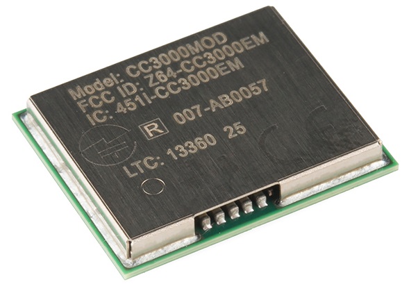
I decided to use WIFI modules for this week's assignment. Since we had CC3000 Wifi module chip in our lab i decided to go with the same. The reason to choose the same was since my it would be useful for my final project for controlling equipments wirelessly.
.
.
.
.
.

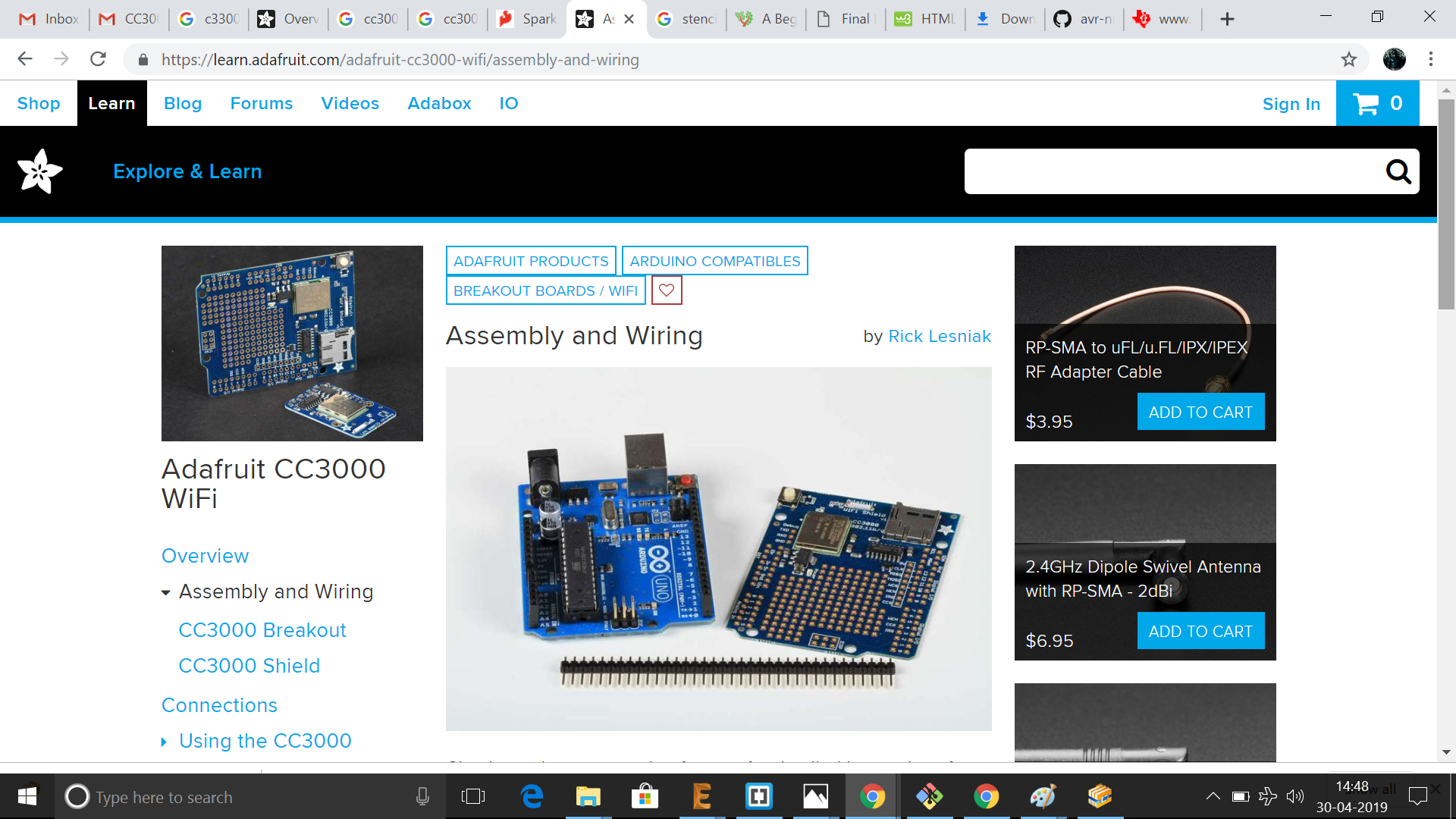
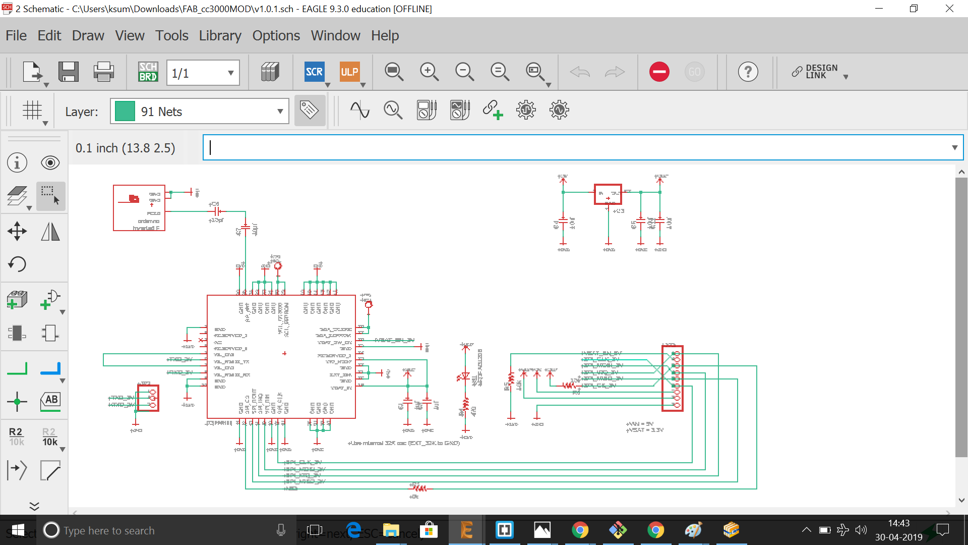
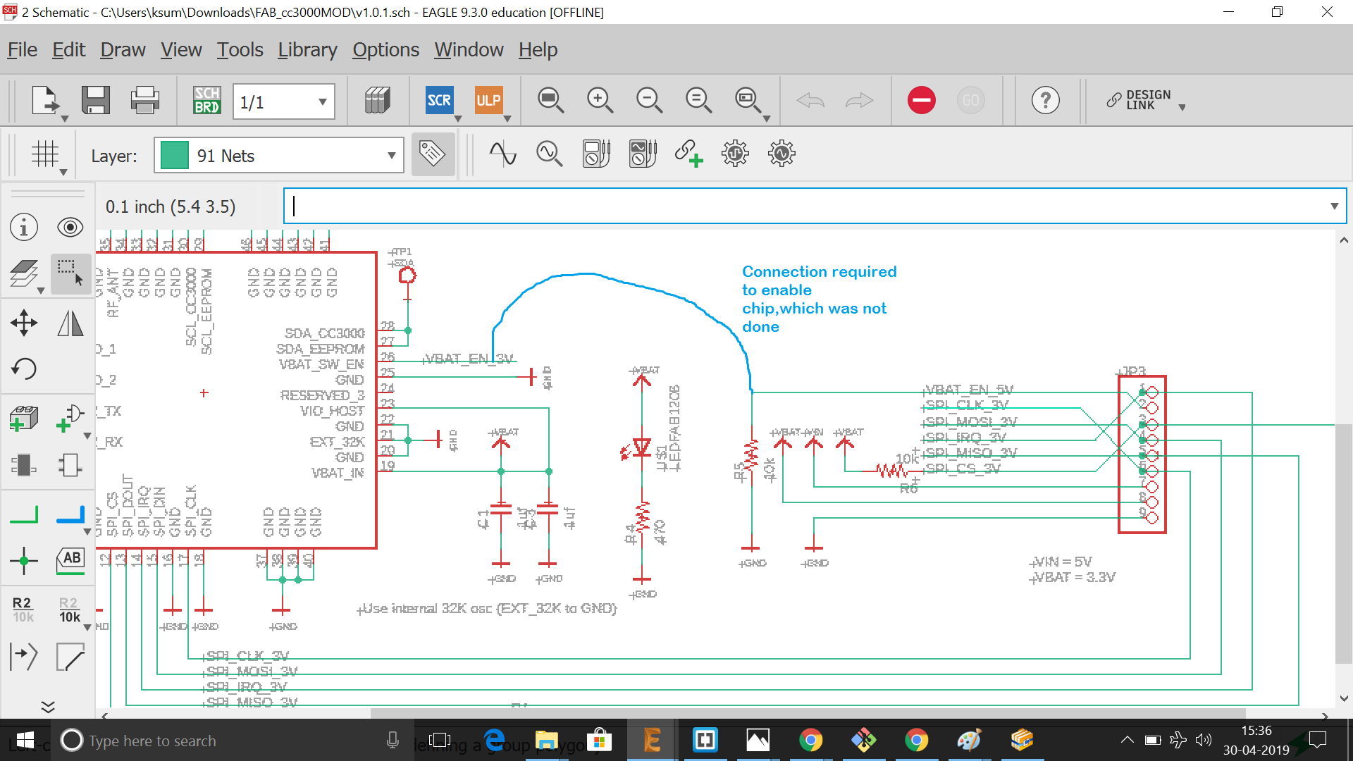
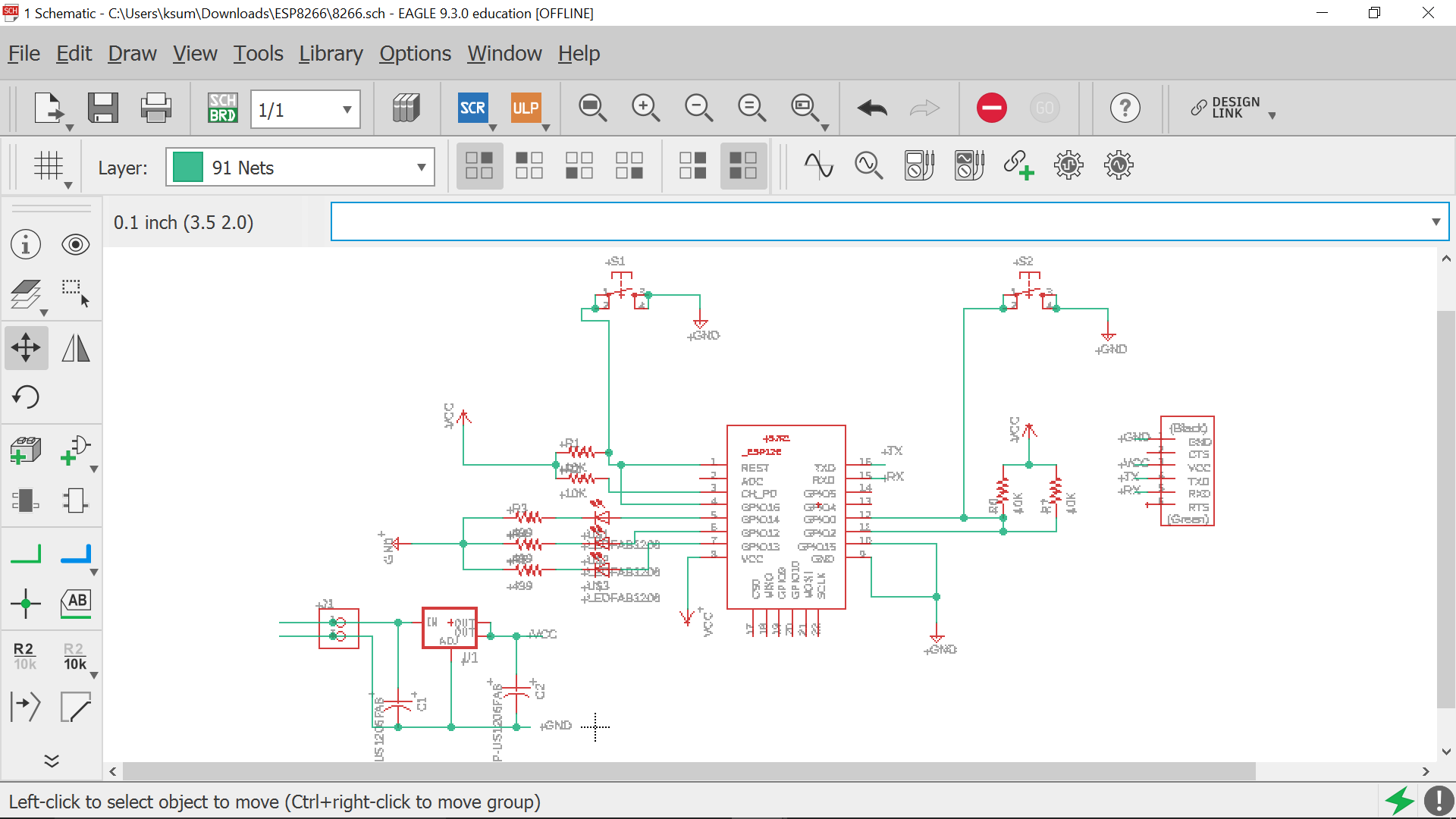
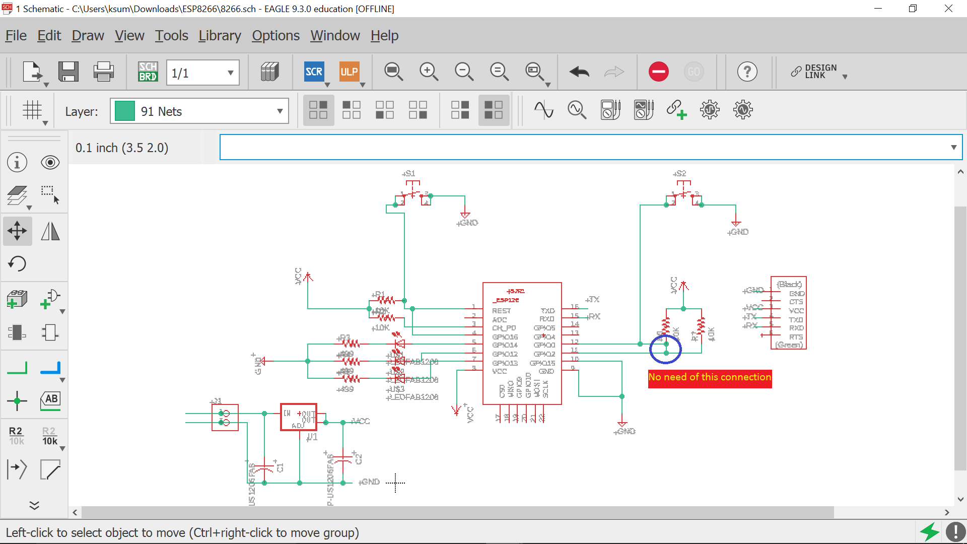
First step was to get a minimum circuit for operation of the wifi module.The circuit available from adafruit library was used as below, for setting up
.
.
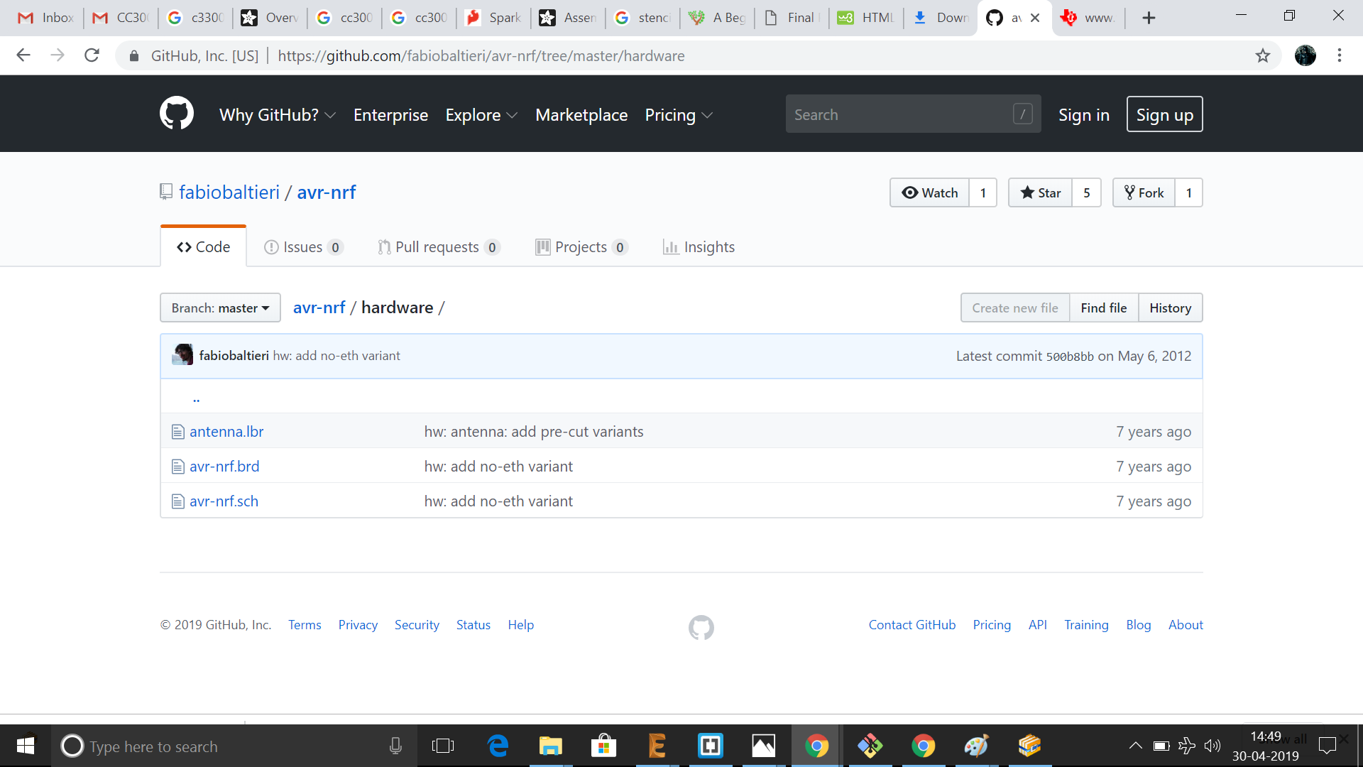
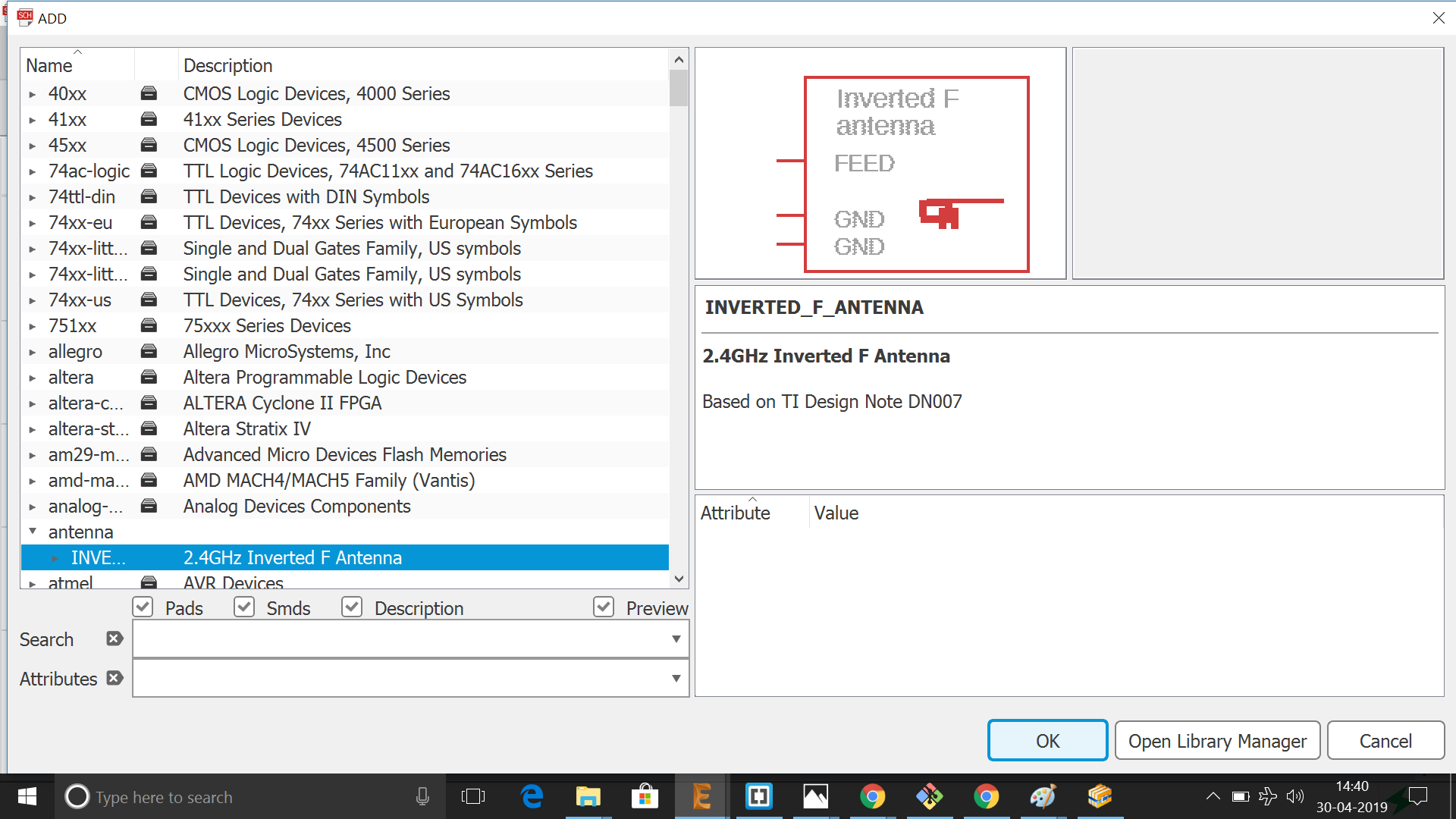
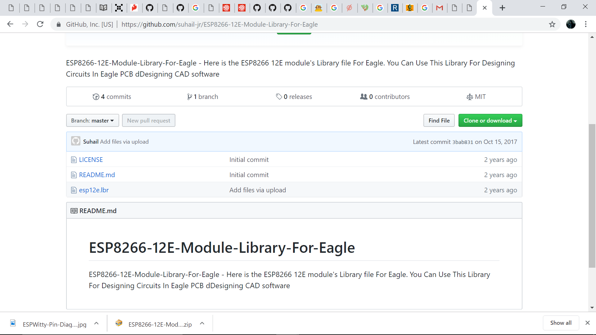
The eagle library required for the the module was added. Since the scheme doesn't have an inbuilt antenna, an antenna was used which was obtained from here. The library was added in eagle as below:
.
.
.
.
.
.
.
.
.
.
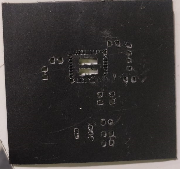
As we can see from back side view that the pins are in backside, inorder to solder the component we need to use the stencling method to work with the same. Since we didn't have the required paper for making the stencil, I tried to laser cut the design in an available sheet as below.But it was a failure as below
.
.
.
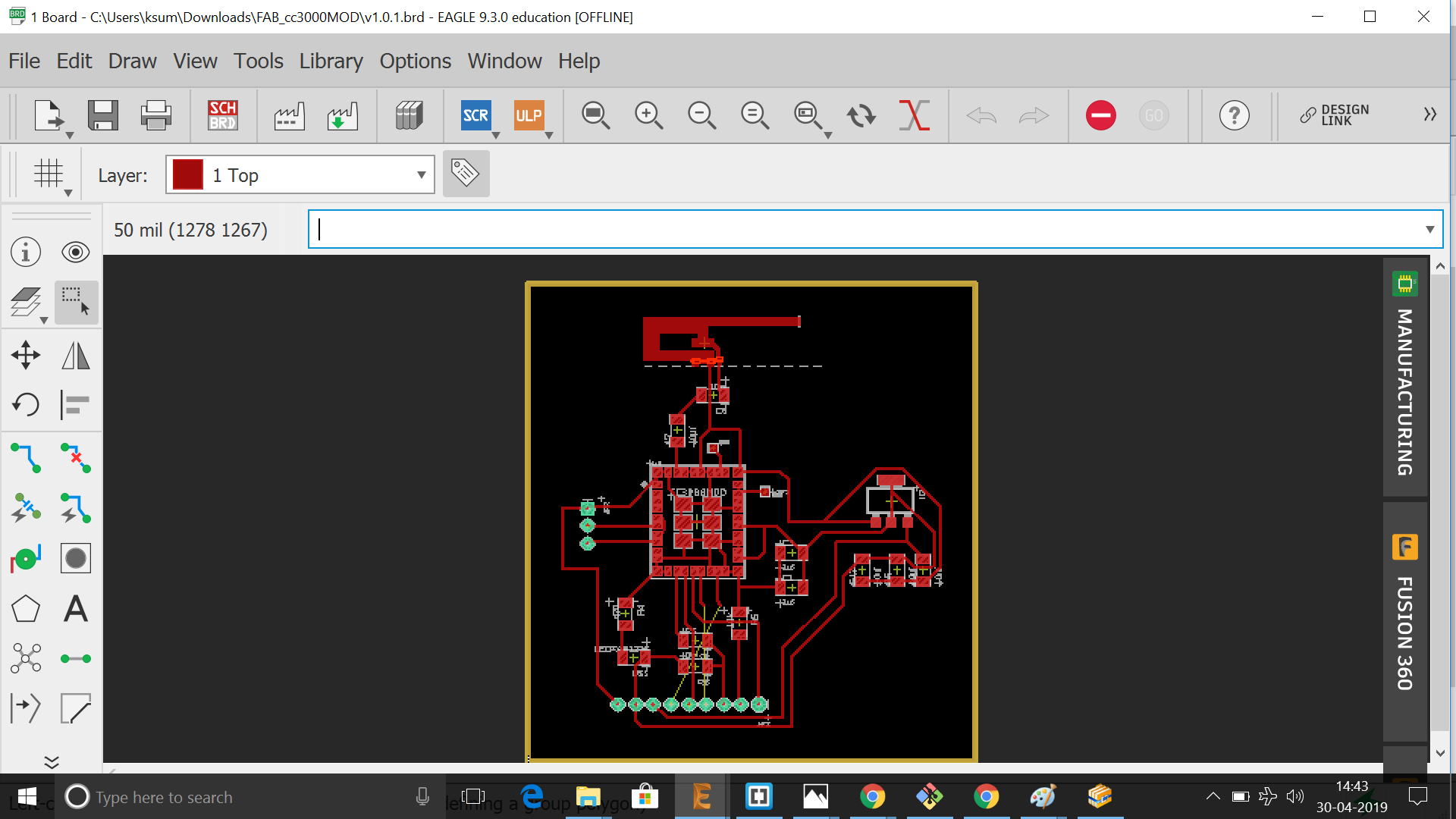
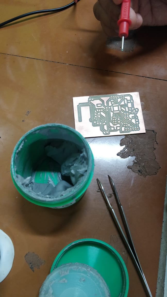
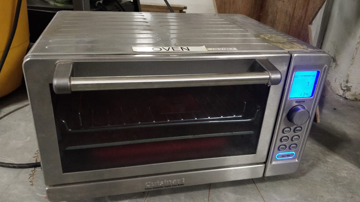
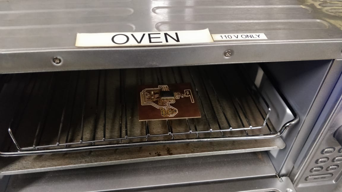
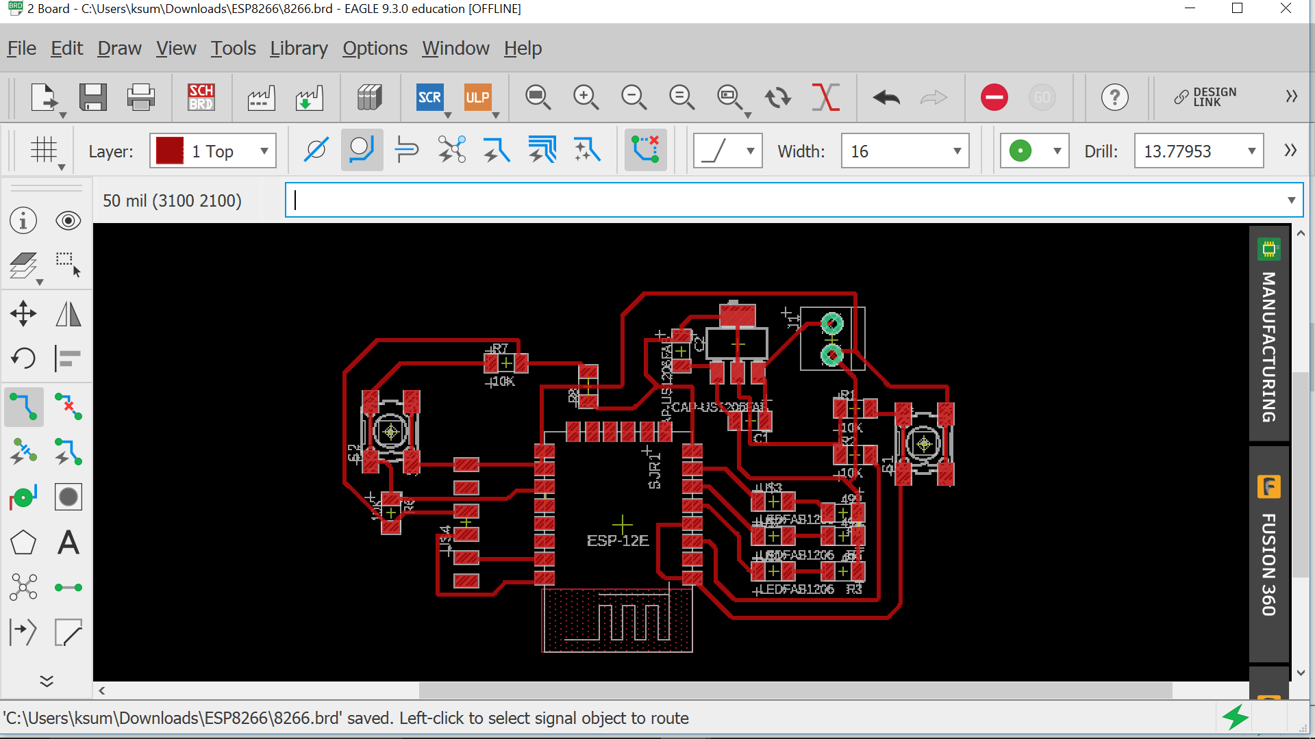
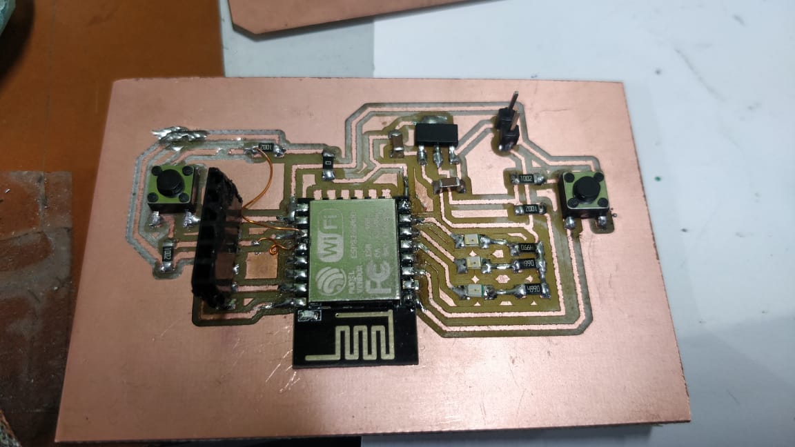
The PCB was now milled and the component was placed in oven after filling the necessary portions with solder paste.
.
.
.
.
.
.
.
.
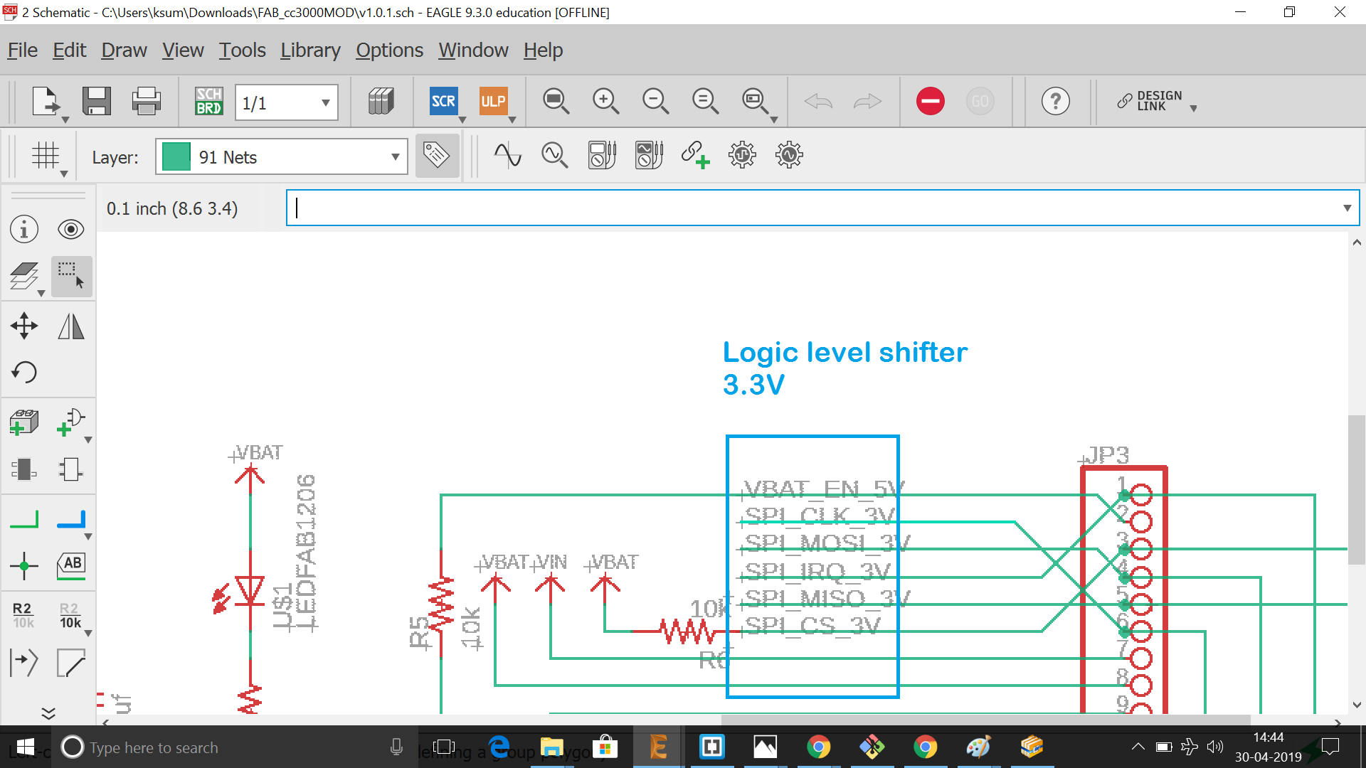
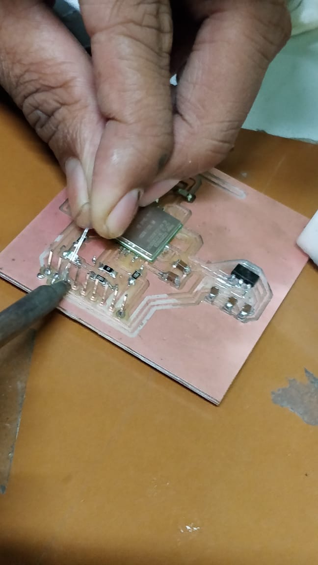
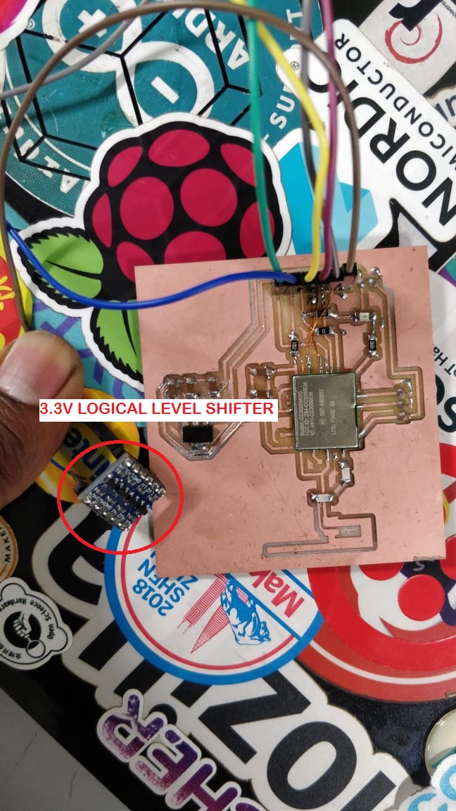
After soldering the components, since the chips works in 3.3 V and the arduino board that i am going to connect works at 5 V , an external 3.3V logical level shifter was added as below
.
.
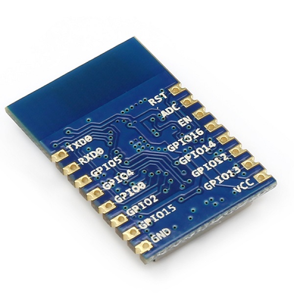
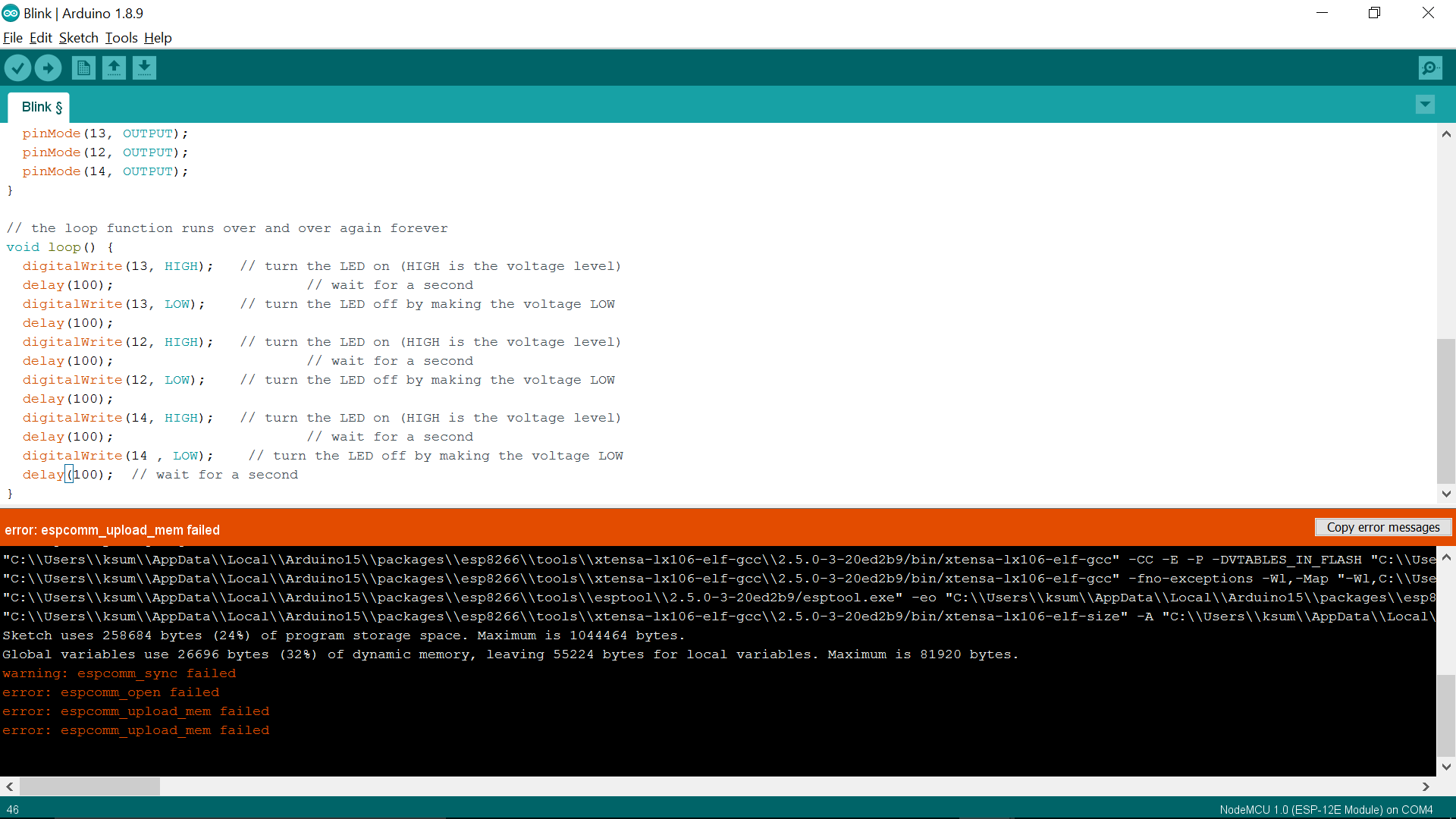
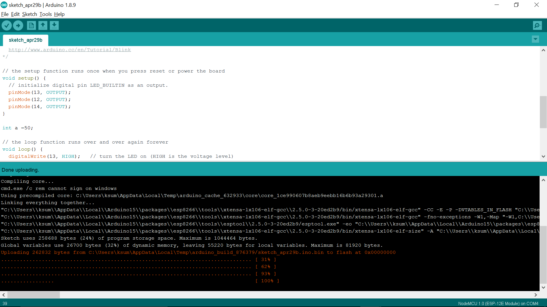
But when i tried to program the bootloader, there was an issue in programming the same.So i decided to use ESP8266 module for the same purpose. So i ordered an ESP8266 chip for the same since it was not available in our lab
.
.
.
The ESP8266 WiFi Module is a self contained system-on-a-chip (SOC) with integrated TCP/IP protocol stack that can give any microcontroller access to your WiFi network. The ESP8266 is capable of either hosting an application or offloading all Wi-Fi networking functions from another application processor.Each ESP8266 module comes pre-programmed with an AT command set firmware by which we could connect this to any atmega or arduino device
.
.
.
.
.
.
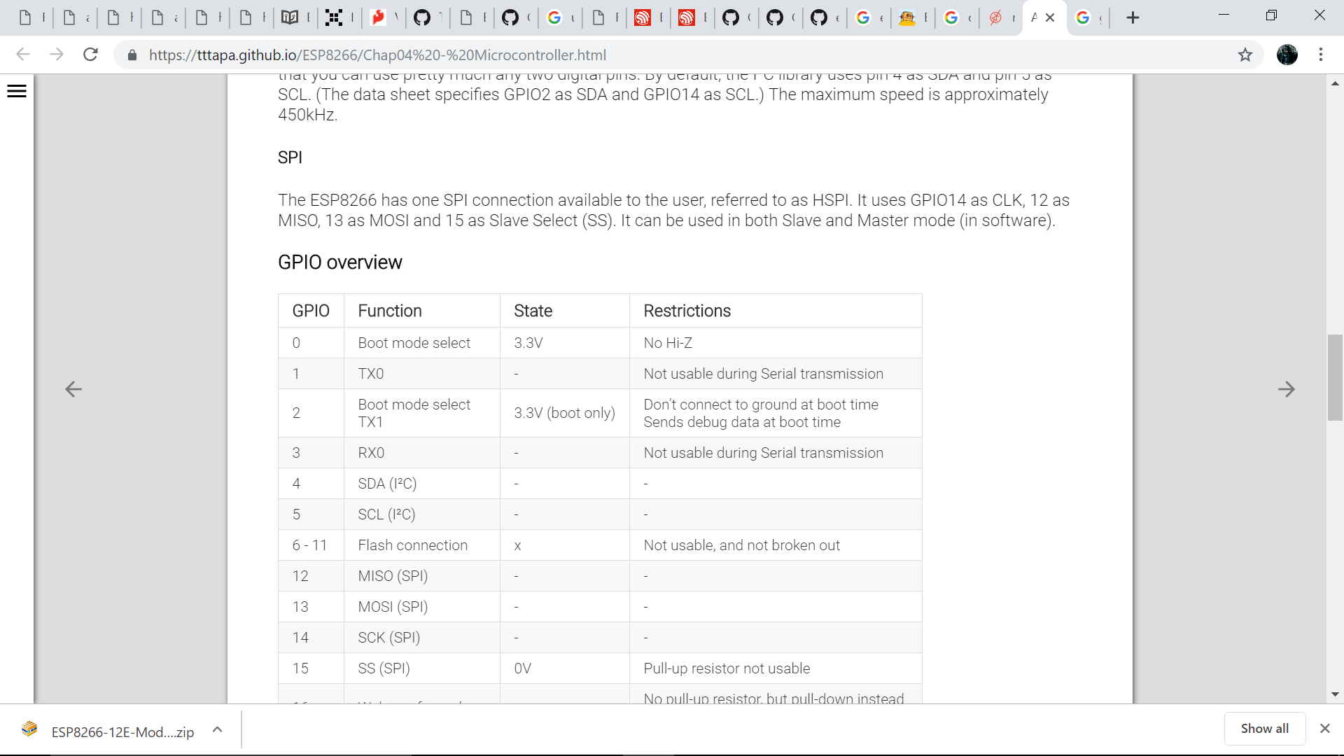
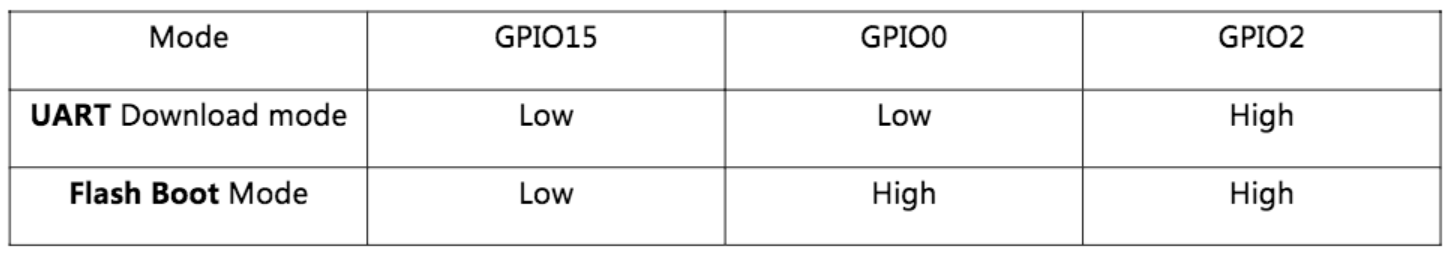
Since there are different modes for the operation and programming of ESP 8266 , the details can be obtained from here
.
.
.
.
.
.
.
.
.
.
.
.
.
.
.
.
.
.
.
.
.
.
.
.
.
.
.
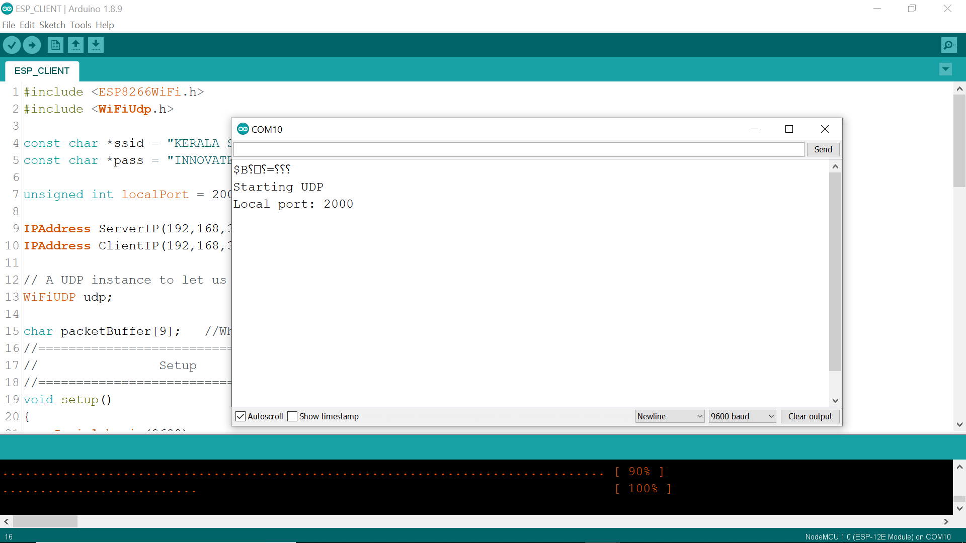
Next step was to have the two boards communicate with each other. Here i will try to use the two esp boards communicate through UDP protocol as wireless serial comunication. UDP gives advantage of sending one message to all ESP8266 devices on same network at the same time using broadcast. For the same i connected the two esp boards to my system through ftdi cable.
.
.
#include <ESP8266WiFi.h>
#include <WiFiUdp.h>

const char *ssid = "KERALA STARTUP MISSION";
const char *pass = "INNOVATE@KTIZ";

unsigned int localPort = 2000; // local port to listen for UDP packets

IPAddress ServerIP(192,168,10,1);
IPAddress ClientIP(192,168,10,2);

// A UDP instance to let us send and receive packets over UDP
WiFiUDP udp;

char packetBuffer[9];   //Where we get the UDP data
//=======================================================================
//                Setup
//=======================================================================
void setup()
{
    Serial.begin(9600);
    Serial.println();
    WiFi.softAP(ssid, pass);    //Create Access point

    //Start UDP
    Serial.println("Starting UDP");
    udp.begin(localPort);
    Serial.print("Local port: ");
    Serial.println(udp.localPort());
}
//======================================================================
//                MAIN LOOP
//======================================================================
void loop()
{
    int cb = udp.parsePacket();
    if (!cb)
    {
      //If serial data is recived send it to UDP
      if(Serial.available()>0)
        {
        udp.beginPacket(ClientIP, 2000);
        //Send UDP requests are to port 2000

        char a[1];
        a[0]=char(Serial.read()); //Serial Byte Read
        udp.write(a,1); //Send one byte to ESP8266
        udp.endPacket();
        }
    }
    else {
      // We've received a UDP packet, send it to serial
      udp.read(packetBuffer, 1); // read the packet into the buffer, we are reading only one byte
      Serial.print(packetBuffer);
      delay(20);
    }}
.
.
#include <ESP8266WiFi.h>
#include <WiFiUdp.h>

const char *ssid = "KERALA STARTUP MISSION";
const char *pass = "INNOVATE@KTIZ";

unsigned int localPort = 2000; // local port to listen for UDP packets

IPAddress ServerIP(192,168,5,1);
IPAddress ClientIP(192,168,5,2);

// A UDP instance to let us send and receive packets over UDP
WiFiUDP udp;

char packetBuffer[9];   //Where we get the UDP data
//======================================================================
//                Setup
//======================================================================
void setup()
{
    Serial.begin(9600);
    Serial.println();

    WiFi.begin(ssid, pass);   //Connect to access point

    Serial.println("");

  // Wait for connection
  while (WiFi.status() != WL_CONNECTED) {
    delay(500);
    Serial.print(".");
  }
  Serial.println("");
  Serial.print("Connected to ");
  Serial.println(ssid);
  Serial.print("IP address: ");
  Serial.println(WiFi.localIP());

    //Start UDP
    Serial.println("Starting UDP");
    udp.begin(localPort);
    Serial.print("Local port: ");
    Serial.println(udp.localPort());
}
//======================================================================
//                MAIN LOOP
//======================================================================
void loop()
{
    int cb = udp.parsePacket();
    if (!cb)
    {
      //If serial data is recived send it to UDP
      if(Serial.available()>0)
        {
        udp.beginPacket(ServerIP, 2000);  //Send Data to Master unit
        //Send UDP requests are to port 2000

        char a[1];
        a[0]=char(Serial.read()); //Serial Byte Read
        udp.write(a,1); //Send one byte to ESP8266
        udp.endPacket();
        }
    }
    else {
      // We've received a UDP packet, send it to serial
      udp.read(packetBuffer, 1); // read the packet into the buffer, we are reading only one byte
      Serial.print(packetBuffer);
      delay(20);
    }
}
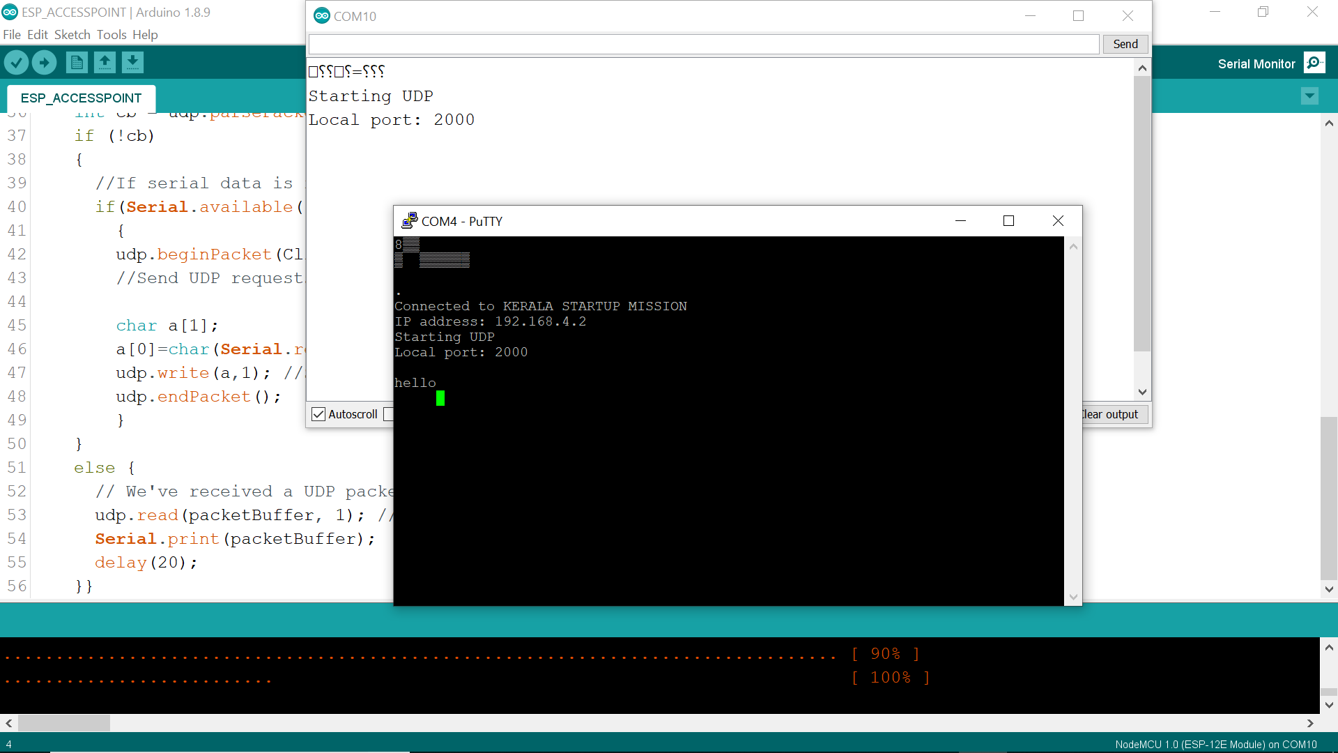
Serial monitor in arduino was used for sending data from one ESP. 'Putty' was being used to get data from the other other board. I send a data 'hello' as serial input and was received in the second device which was monitored through putty. The screenshots are as below
.
.
.
.
.
.
.
.
.
#include <ESP8266WiFi.h>

#include "WemoSwitch.h"
#include "WemoManager.h"
#include "CallbackFunction.h"

// prototypes
boolean connectWifi();

//on/off callbacks
void lightOn();
void lightOff();
void secondOn();
void secondOff();

//------- Replace the following! ------
char ssid[] = "xxx";       // your network SSID (name)
char password[] = "yyyy";  // your network key

WemoManager wemoManager;
WemoSwitch *light = NULL;
WemoSwitch *second = NULL;

const int ledPin = 13;

void setup()
{
  Serial.begin(115200);

  // Set WiFi to station mode and disconnect from an AP if it was Previously
  // connected
  WiFi.mode(WIFI_STA);
  WiFi.disconnect();
  delay(100);

  // Attempt to connect to Wifi network:
  Serial.print("Connecting Wifi: ");
  Serial.println(ssid);
  WiFi.begin(ssid, password);
  while (WiFi.status() != WL_CONNECTED) {
    Serial.print(".");
    delay(500);
  }
  Serial.println("");
  Serial.println("WiFi connected");
  Serial.println("IP address: ");
  IPAddress ip = WiFi.localIP();
  Serial.println(ip);

  wemoManager.begin();
  // Format: Alexa invocation name, local port no, on callback, off callback
  light = new WemoSwitch("test lights", 80, lightOn, lightOff);
  second = new WemoSwitch("second lights", 81, secondOn, secondOff);
  wemoManager.addDevice(*light);
  wemoManager.addDevice(*second);

  pinMode(ledPin, OUTPUT); // initialize digital ledPin as an output.
  delay(10);
  digitalWrite(ledPin, HIGH); // Wemos BUILTIN_LED is active Low, so high is off
}

void loop()
{
  wemoManager.serverLoop();
}

void lightOn() {
    Serial.print("Switch 1 turn on ...");
    digitalWrite(ledPin, LOW);
}

void lightOff() {
    Serial.print("Switch 1 turn off ...");
    digitalWrite(ledPin, HIGH);
}

void secondOn() {
    Serial.print("Switch 2 turn on ...");
    digitalWrite(ledPin, LOW);
}

void secondOff() {
    Serial.print("Switch 2 turn off ...");
    digitalWrite(ledPin, HIGH);
}
.