
Getting acquianted with fab machines
.
This weeks assignment was to get acquainted with fab tools such as vinyl cutter, laser cutter. So let's start with Vinyl cutter
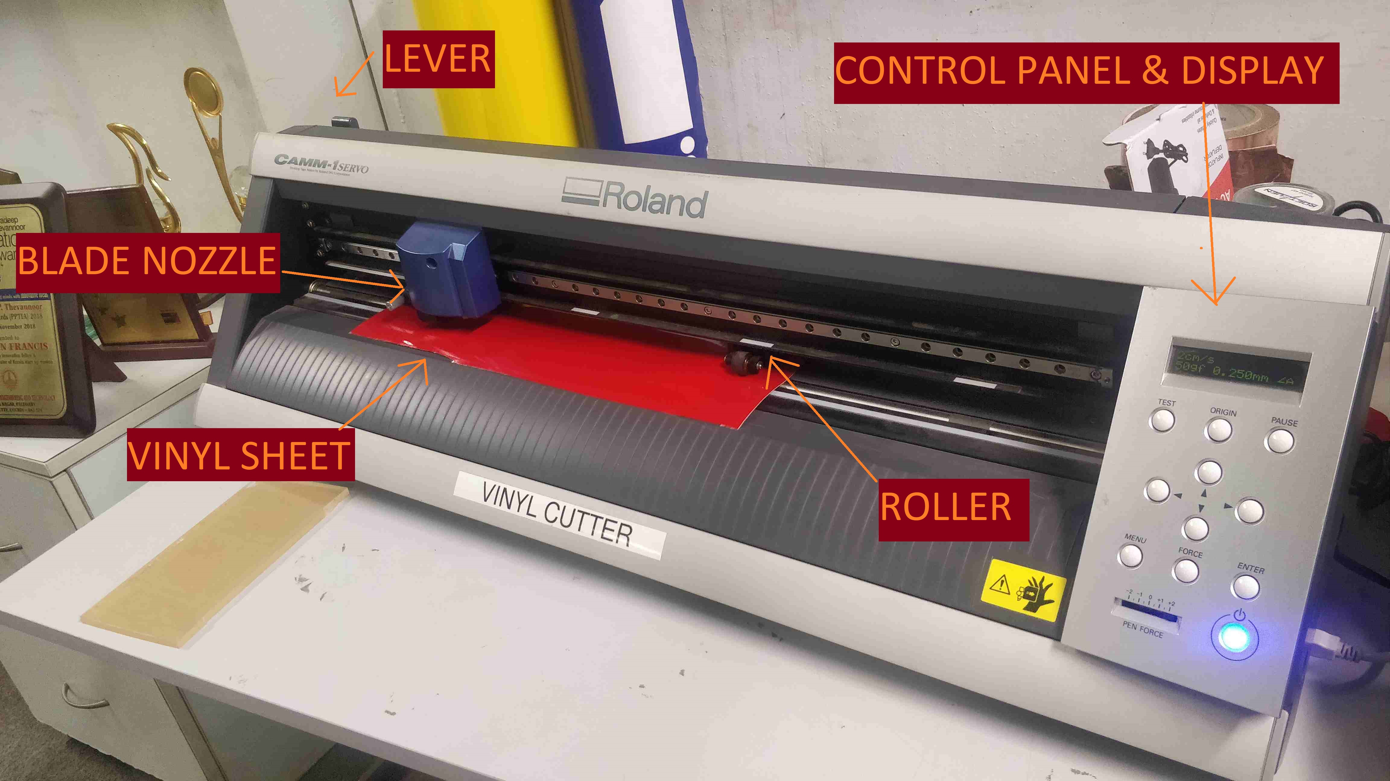
A Vinyl cutter is a controlled machine which could cut vinyl as per the input given to the computer.It could be used for cutting labels and stickers,electronics, woodworking,craft,painting,silk screen printing etc
.
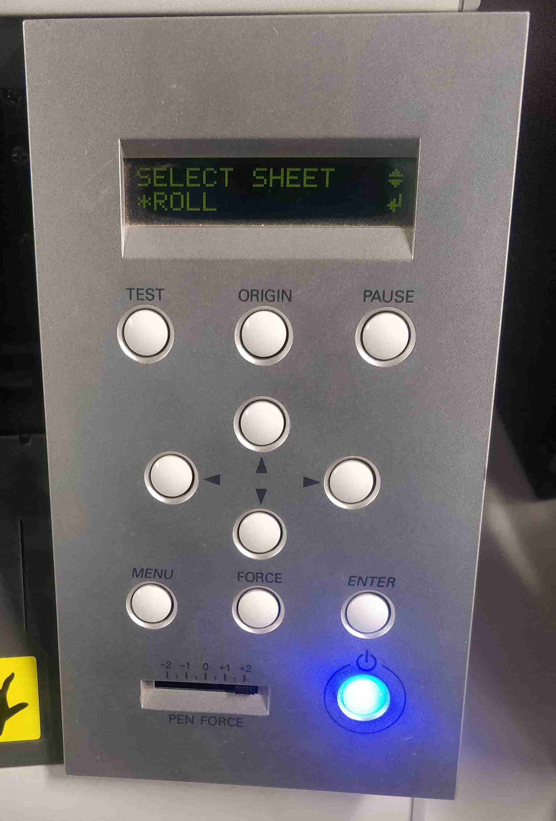
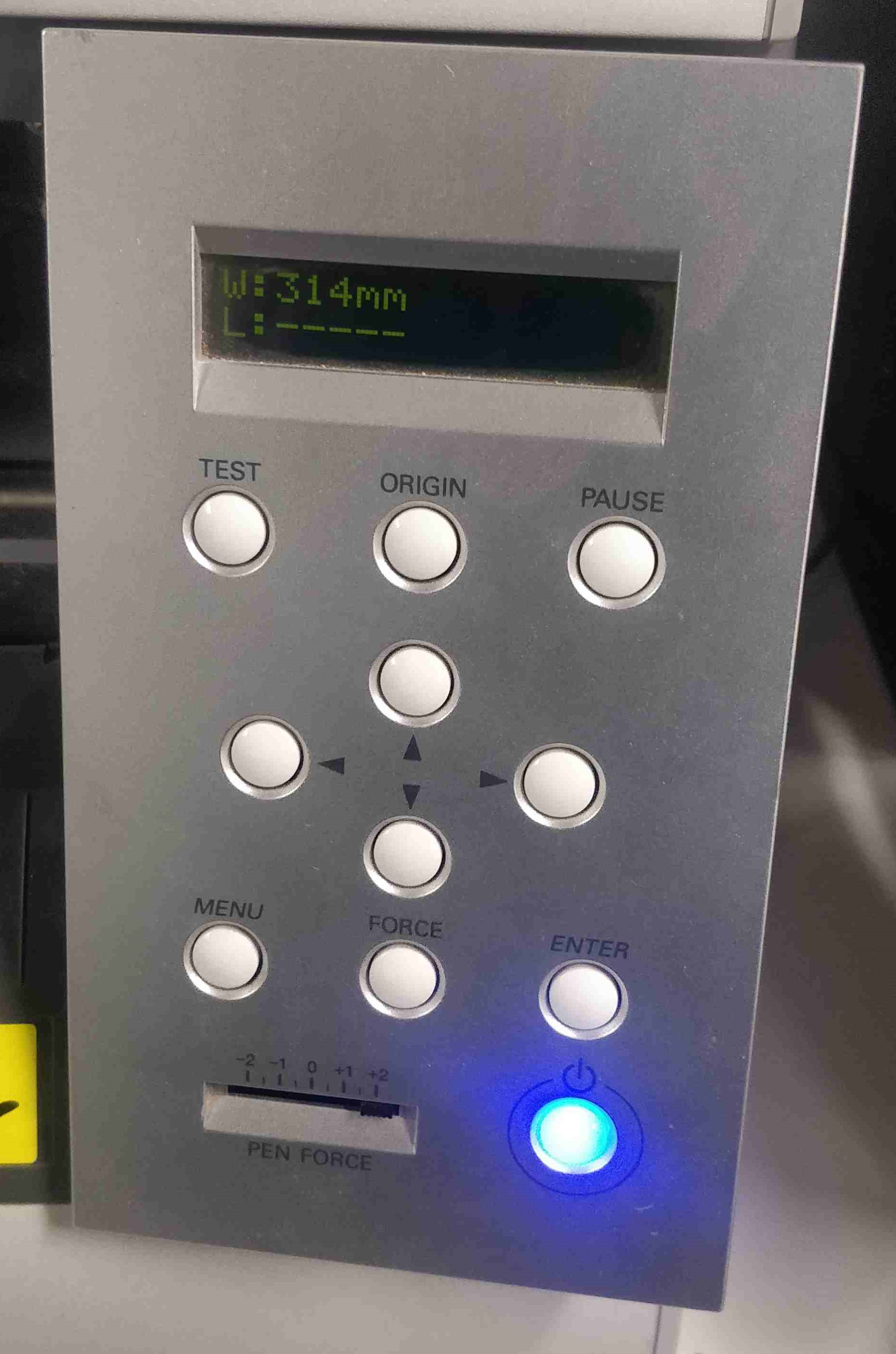
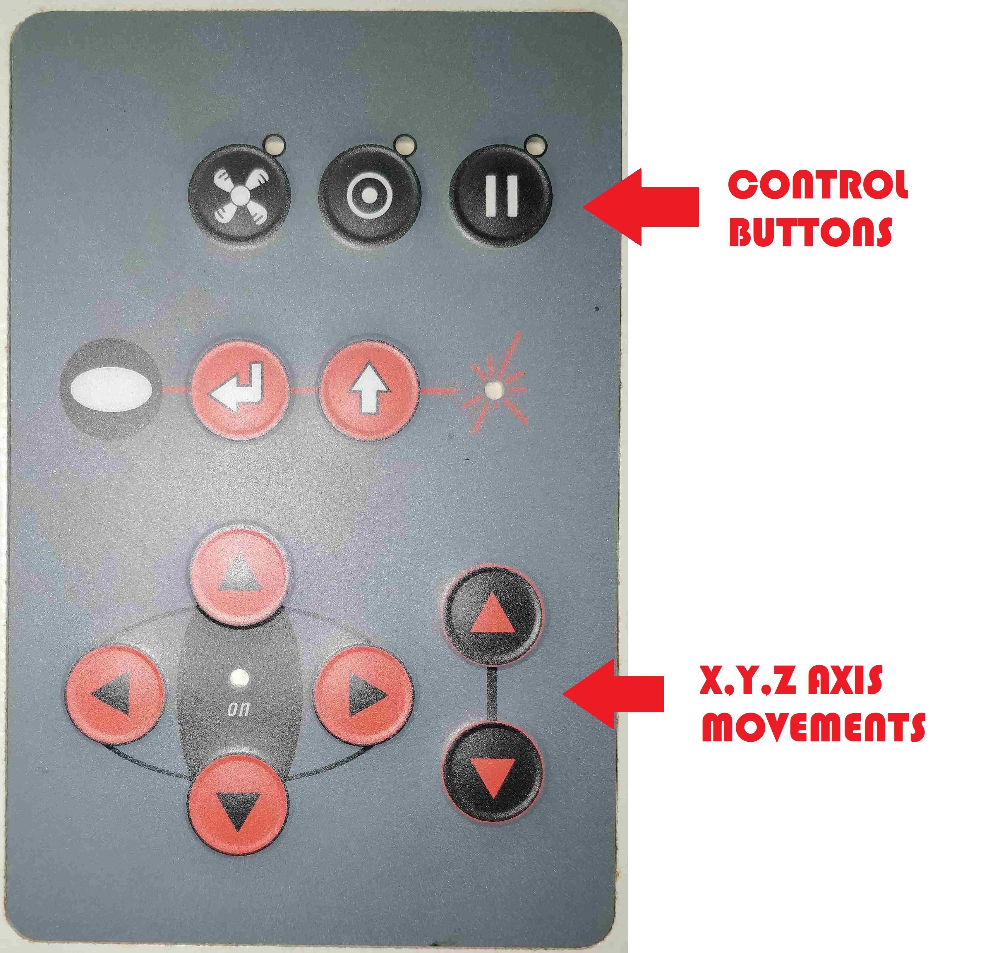
As shown above the vinyl sheet in required colour is placed in the roller by releasing the lever. As the sheet is a roll, the 'roll' option in control panel is selected using the control switches.If the sheet is any piece then select the option according to it. After selecting 'roll', the length of the roll will be detected and displayed by the machine
.
.
.
.
.
Next step is to select a design. As i am a huge fan of Joker (Heath ledger) in batman movie series, i decided to use something related to that. I obtained a png image as below:
.

.
In order to obtain different colours, i loaded the image in photoshop and chnaged as required which is shown below:

.

.
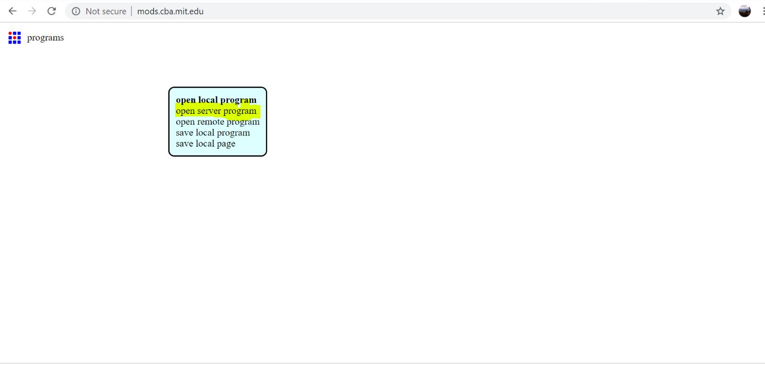
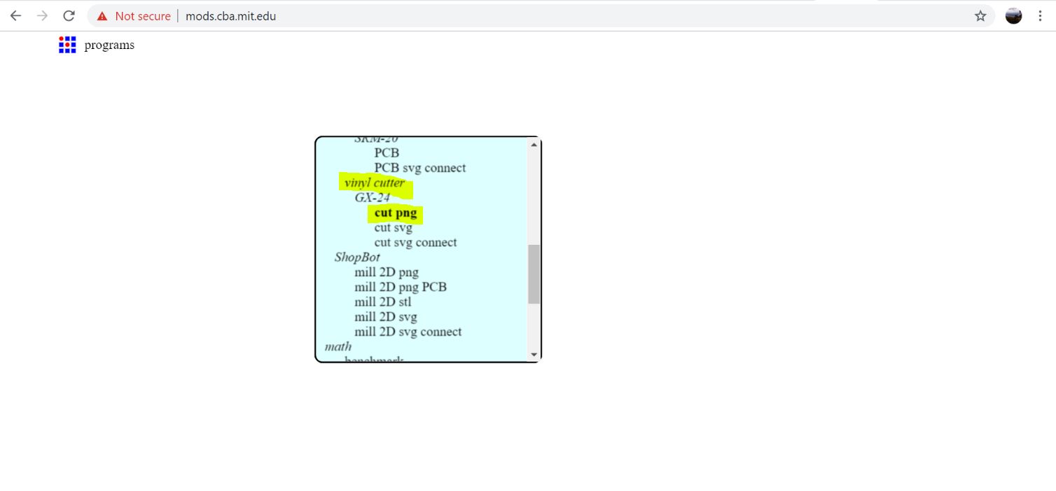
Before going directly to local fab mods, i just decided to load the files in online fabmods.Type mods.cba.mit.edu in browser and options were selected as below:
.
.
.
.
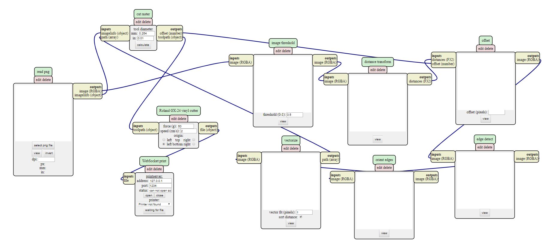
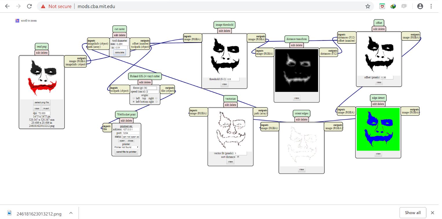
The picture was loaded in the site the paths of the conversion were depicted and output was obtained as below:
.
.
The output file could be cut by selecting printer by giving the printserver address.
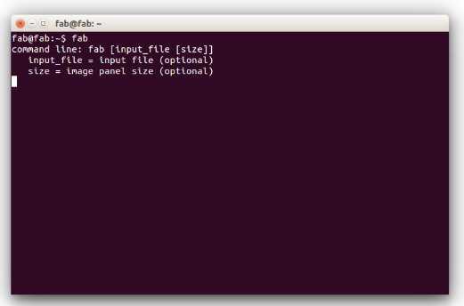
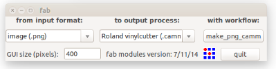
As i have an offline printer available connected to my pc , i opened linux terminal and typed fab
.
.
In the next opened window ,select input format and output process. Input format was selected as png as my files were png. ' Roland Vinyl cutter' was selected from the output process as it was my machine. Click 'Make png camm'
.
.
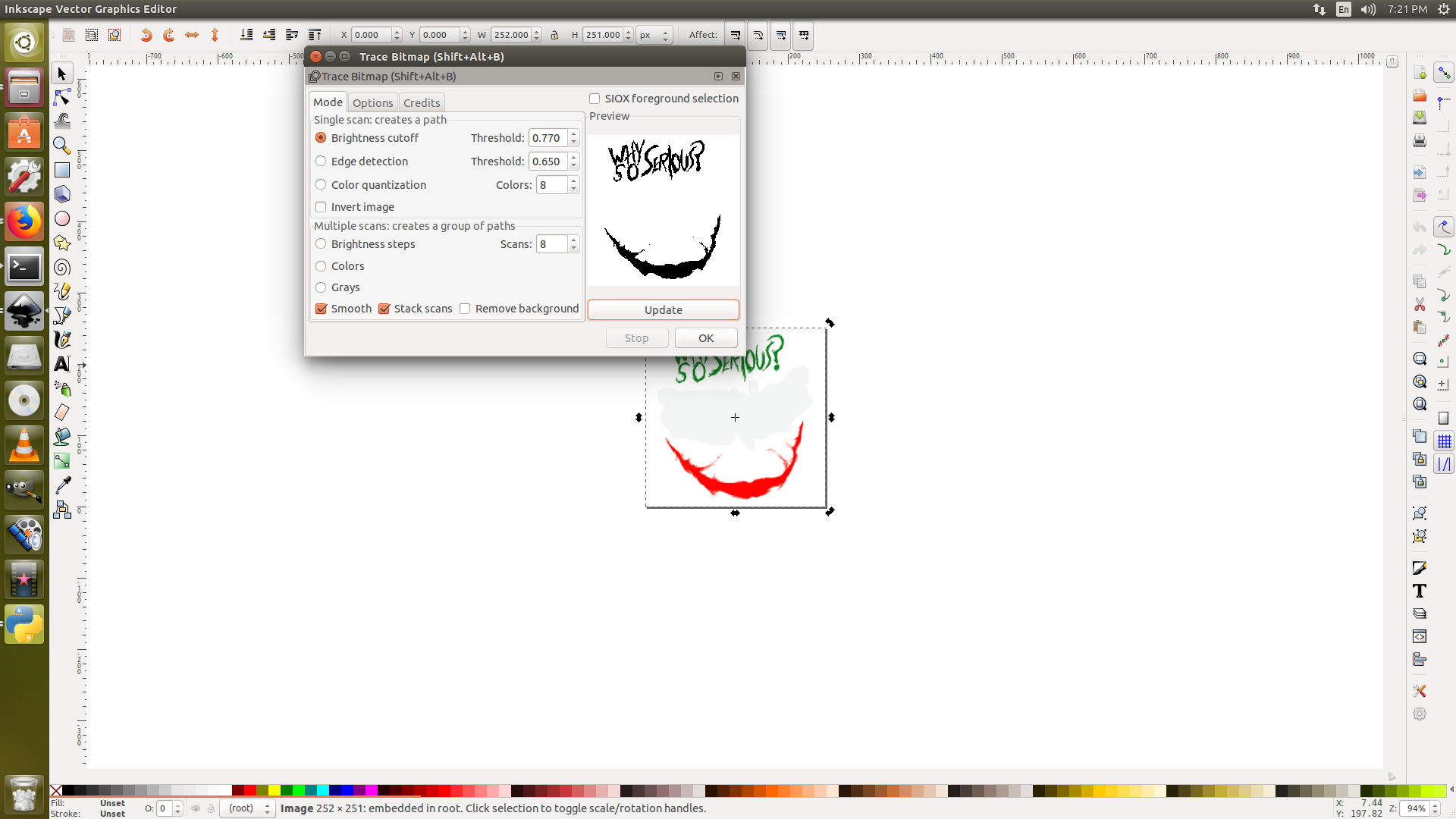
As i needed more size for the cutting portion , i loaded the png files in inkscape and increased the size of the fill and bitmap was traced as below. The files were saved as .svg.
.
.
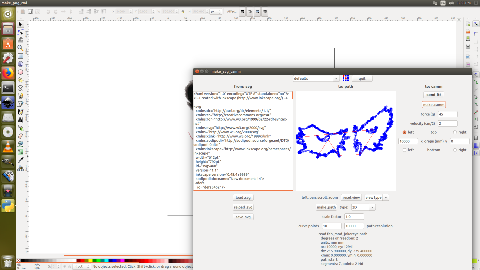
The two files were loaded as svg to cut them in two different coloured vinyl sheets.
.
.
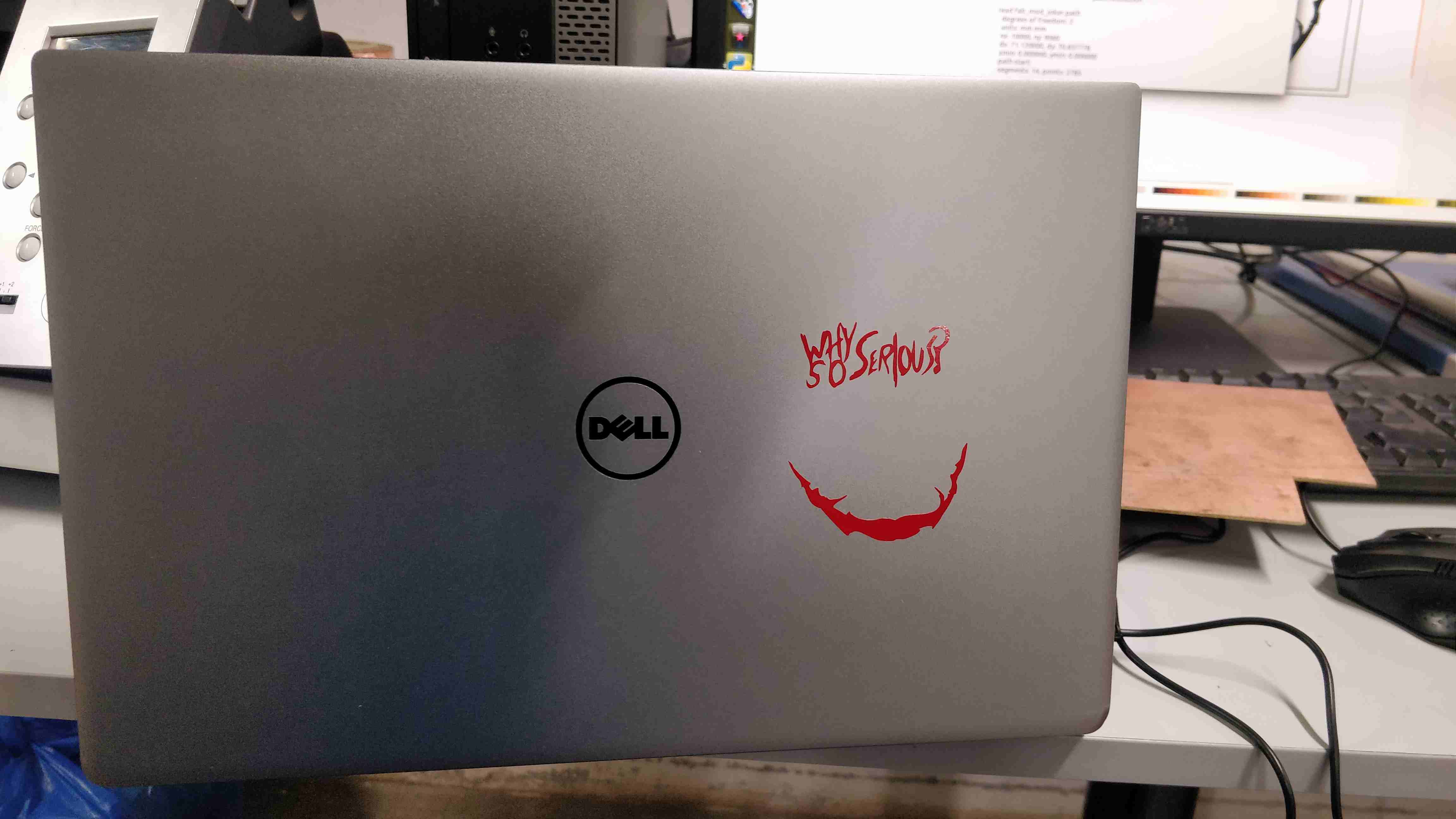
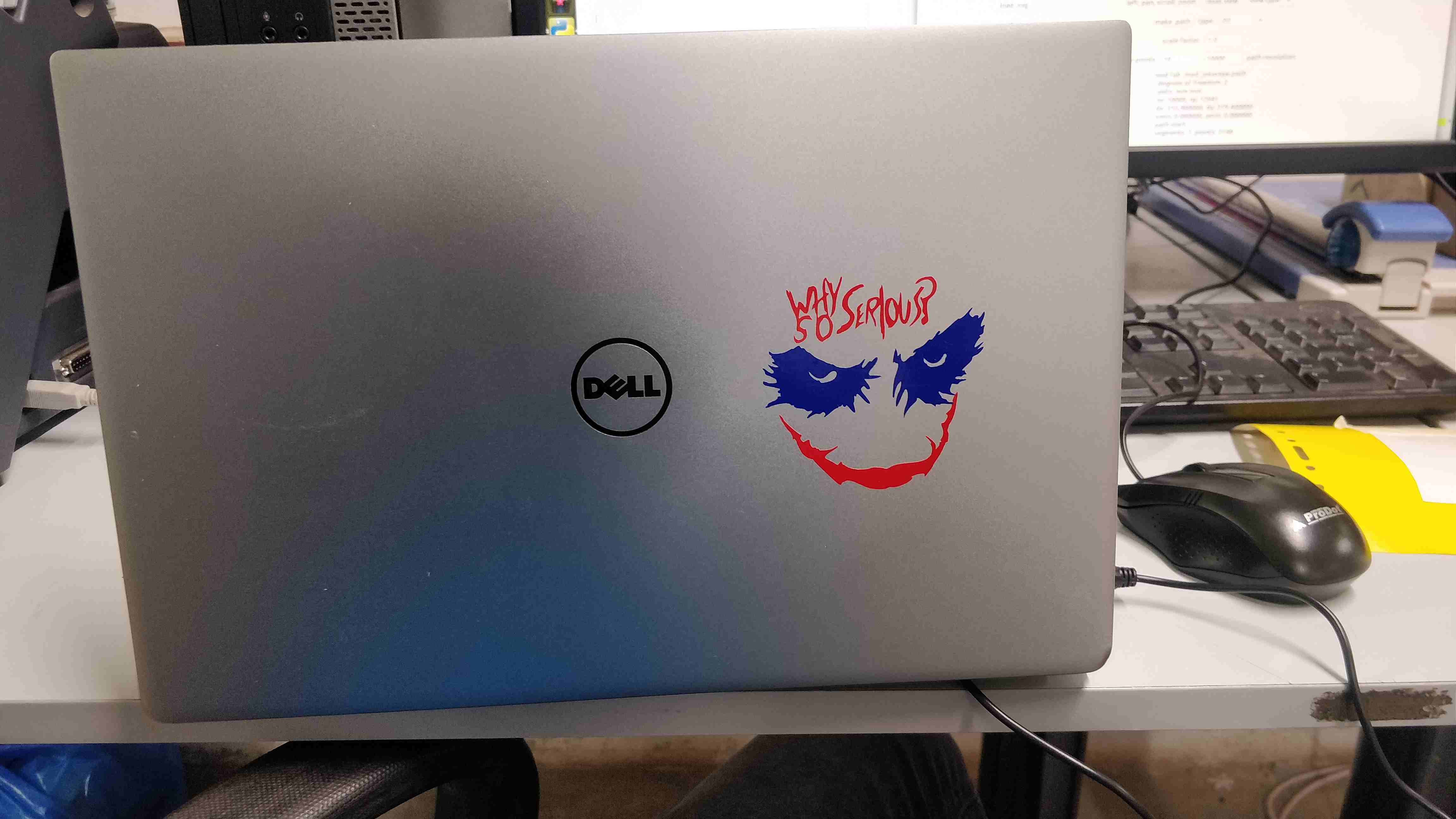
After cutting them, masking tape was used effectively to remove the leftovers and was sticked to my laptop with care. The masking tape was removed slowly with a prediction that the vinyl must have retained to the laptop.
.
.
.
.
.
.
.
.
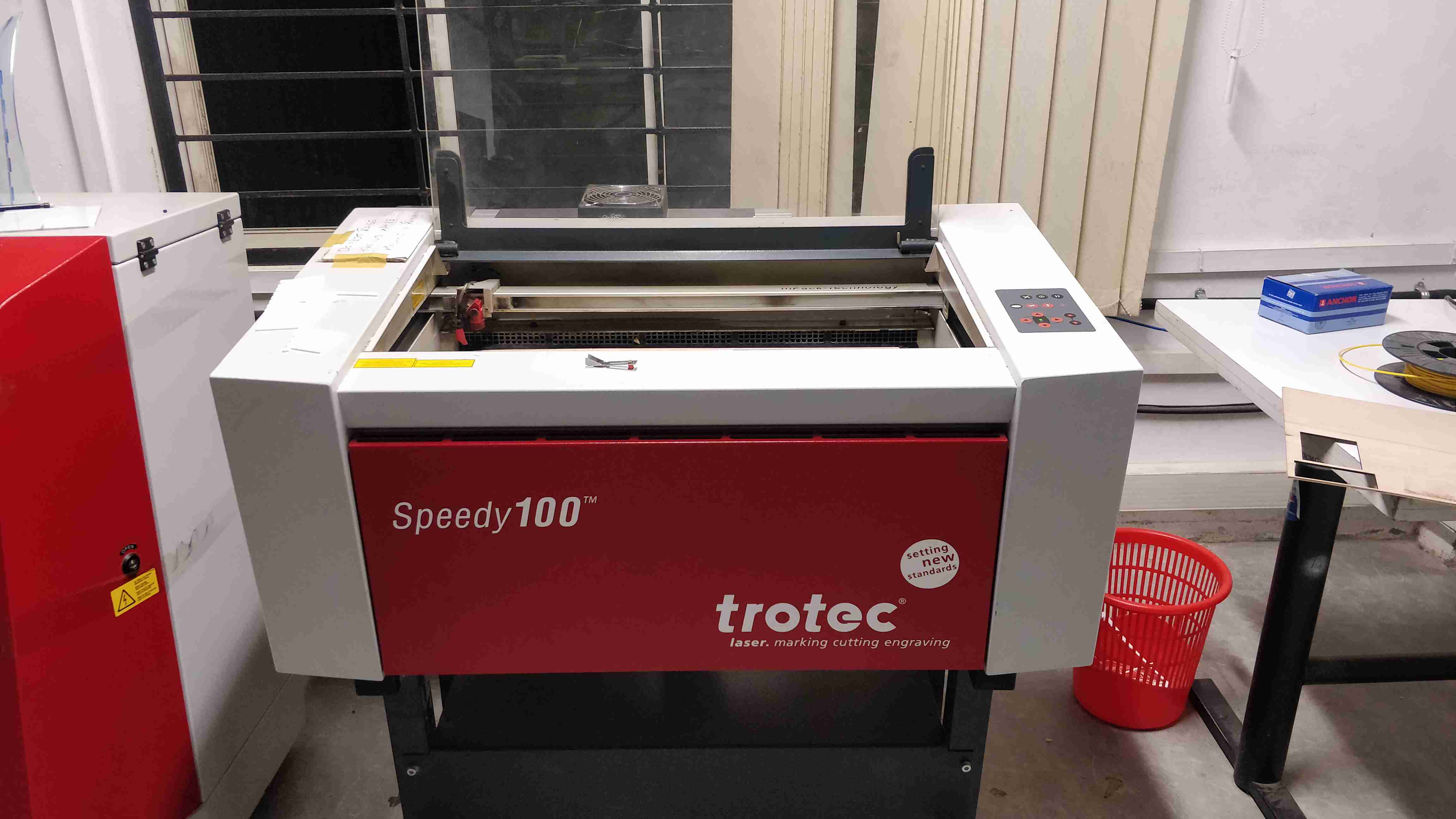
Laser cutting is a technology that uses a laser to cut materials, and is typically used for industrial manufacturing applications, but is also starting to be used by schools, small businesses, and hobbyists. Laser cutter does the work by directing the output of a high-power laser most commonly through optics. The laser optics and CNC (computer numerical control) are used to direct the material or the laser beam generated. A typical commercial laser for cutting materials involved a motion control system to follow a CNC or G-code of the pattern to be cut onto the material. The focused laser beam is directed at the material, which then either melts, burns, vaporizes away, or is blown away by a jet of gas, leaving an edge with a high-quality surface finish. Industrial laser cutters are used to cut flat-sheet material as well as structural and piping materials.
.
.
.
.
.
.
.
.
.
.
.
.
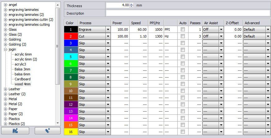
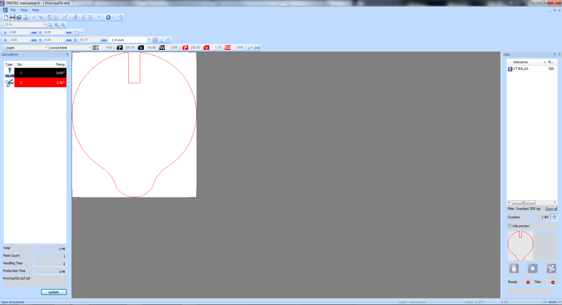
Since i used 4mm plywood, the above configurations were chosen for engraving and cutting the board
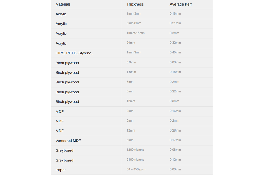
Before moving further we should understand about laser kerf. Let's do that.
.
The laser burns away a portion of material when it cuts through. Kerf means width of material that is removed by the cutting process. The ranges of laser kerf from 0.08mm to 0.45mm, it is depending on the type of material and other conditional factor
.
.
.
.
The kerf width becomes important when we need to fit the material perfectly to another material with the help of joints. If the width of the joint is not perfect, it will become difficult to fit in. The width required for the joints should calculated by subtracting the kerf width from the material thickness
Joint slot width = material thickness - kerf width
OR
Required/Actual/Obtained length = Drawn length - kerf width
The laser pointer is considered as a circle , so the laser will cut an extra of 'kerf/2' ie, radius of the circle , on both sides of the cutting path
.
.
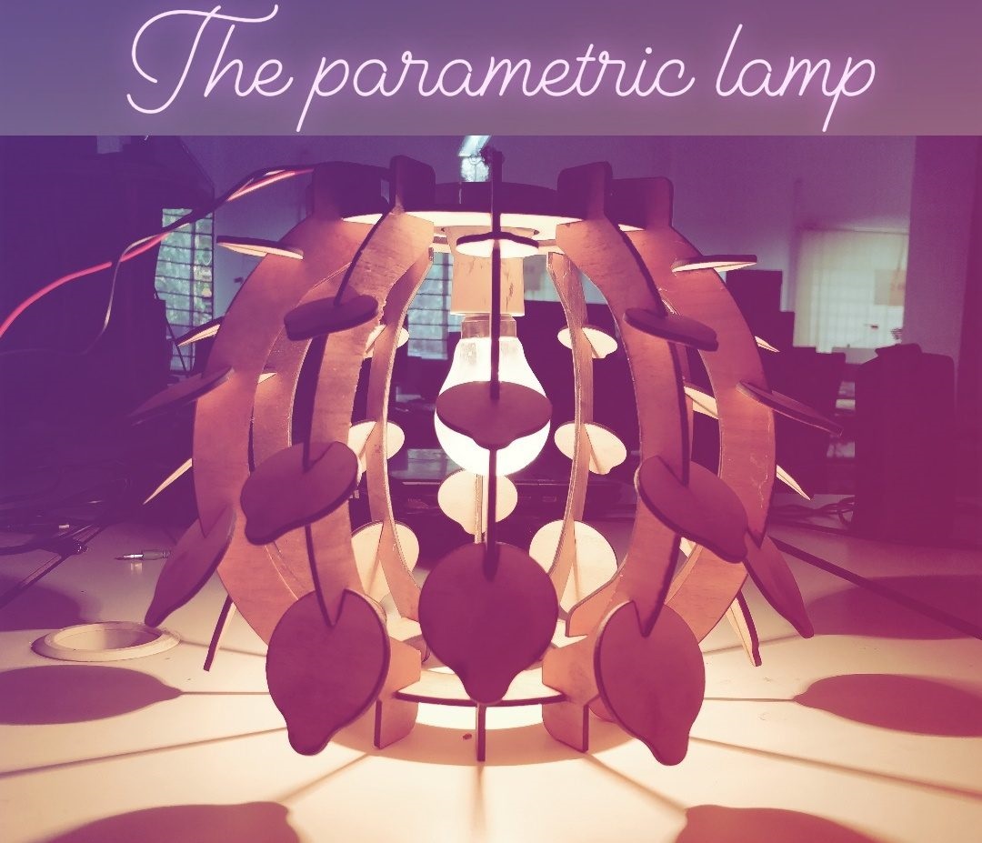
Well i just named it parametric lamp, as it was designed based on single value and most of the other values were depended on this value. For Example the whole design is based on diameter of the 'leaf','sheet_thickness', 'Kerf value'.
The design of the lamp was inspired from my fablab instructor Jogin Francis's image in his fab document. But as he was not able to do it due to time constraints, i thought i would give a try on it as i was on the weekends.
I used 4mm plywood for the making the lamp stand. I used autocad fusion 360 for the design as it seems to be more user friendly tool.
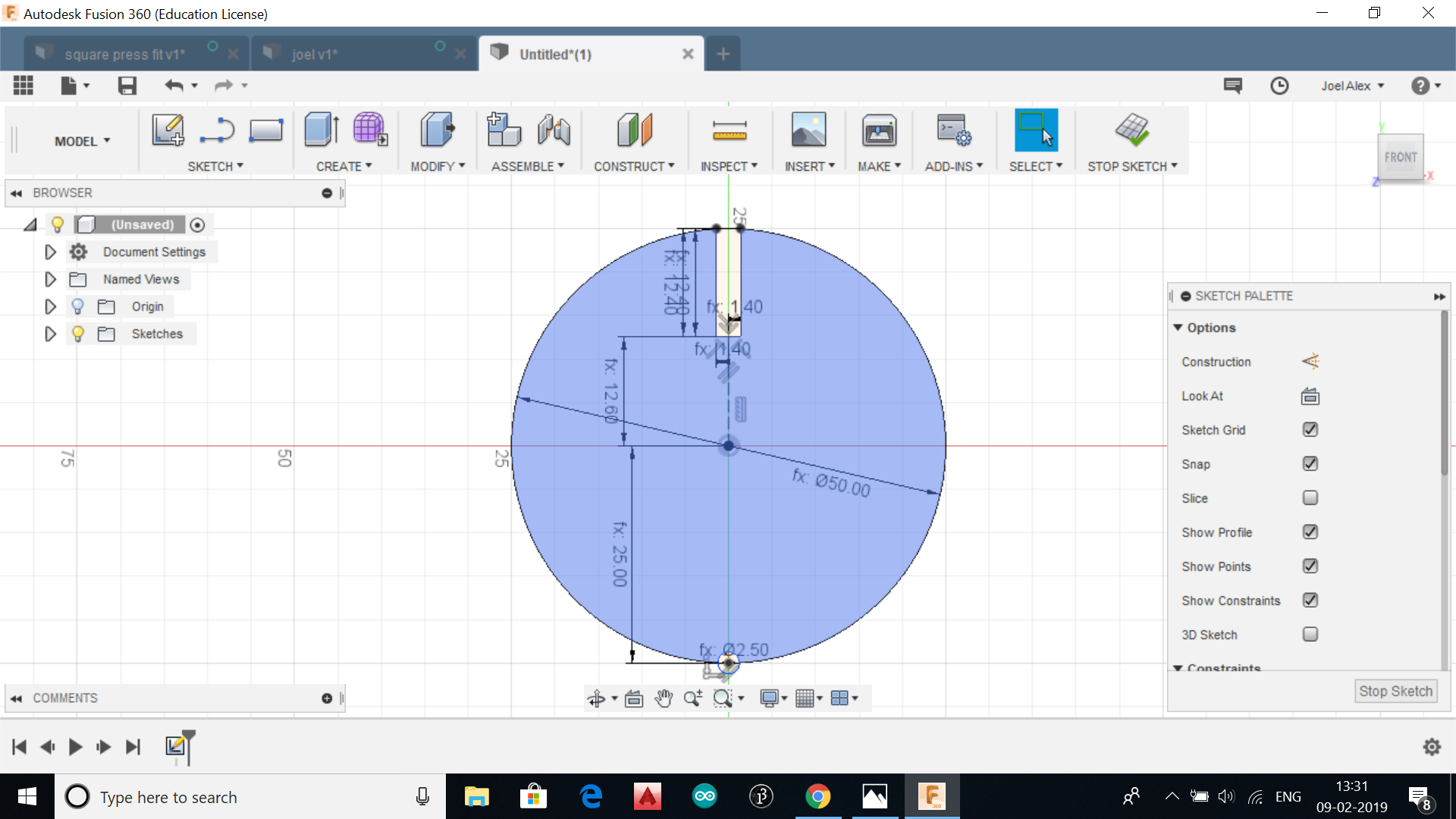
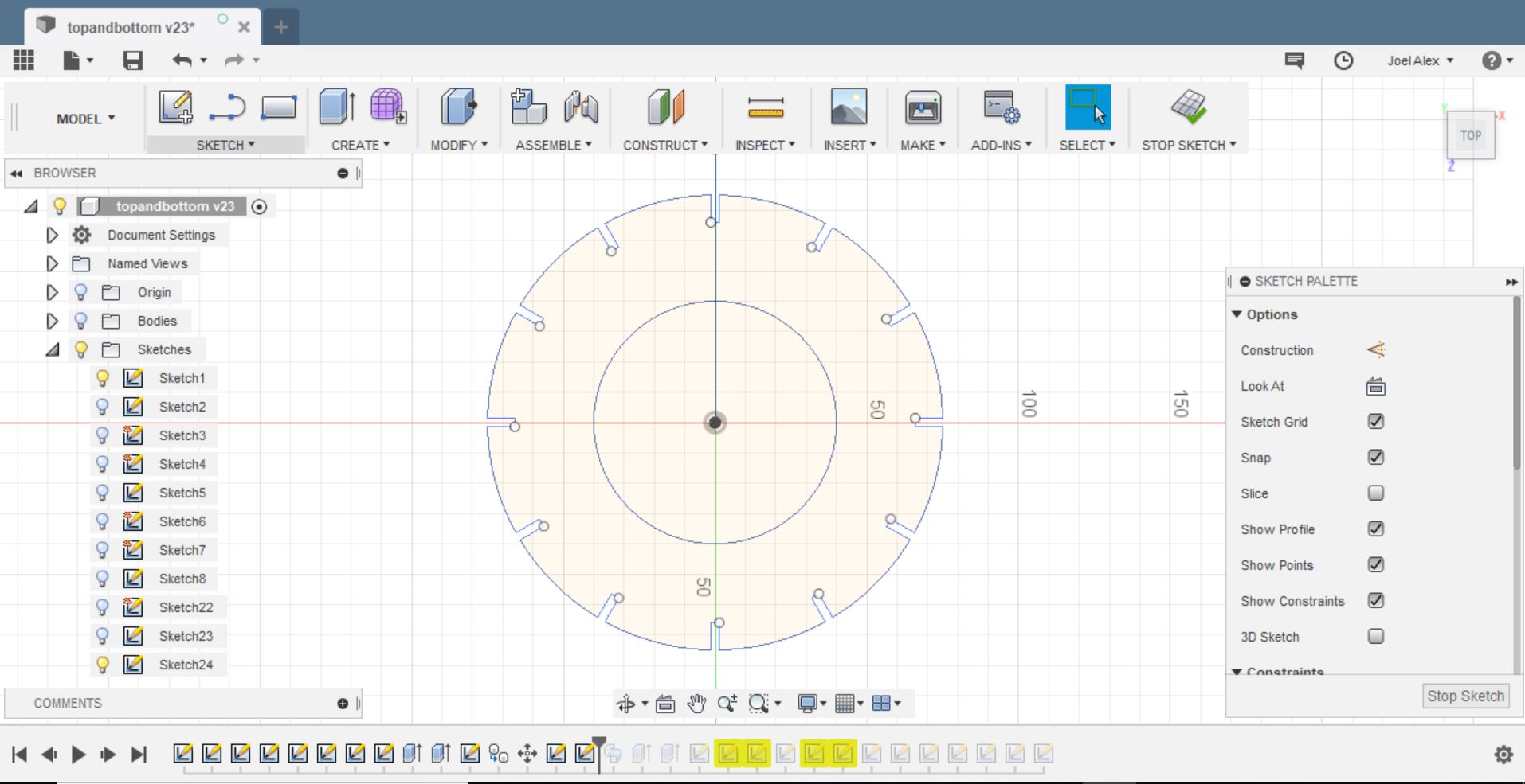
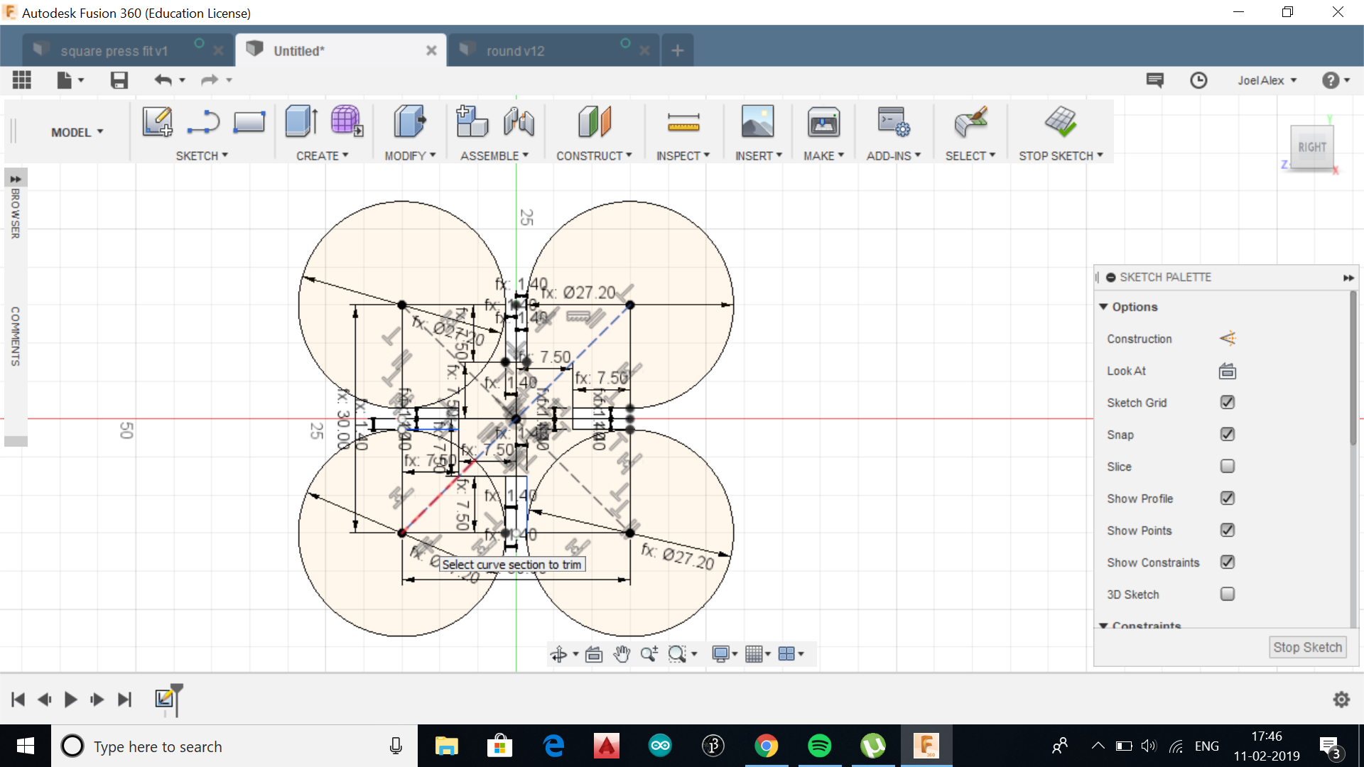
First task was to design the leaf, i considered two circles for top and bottom as shown below
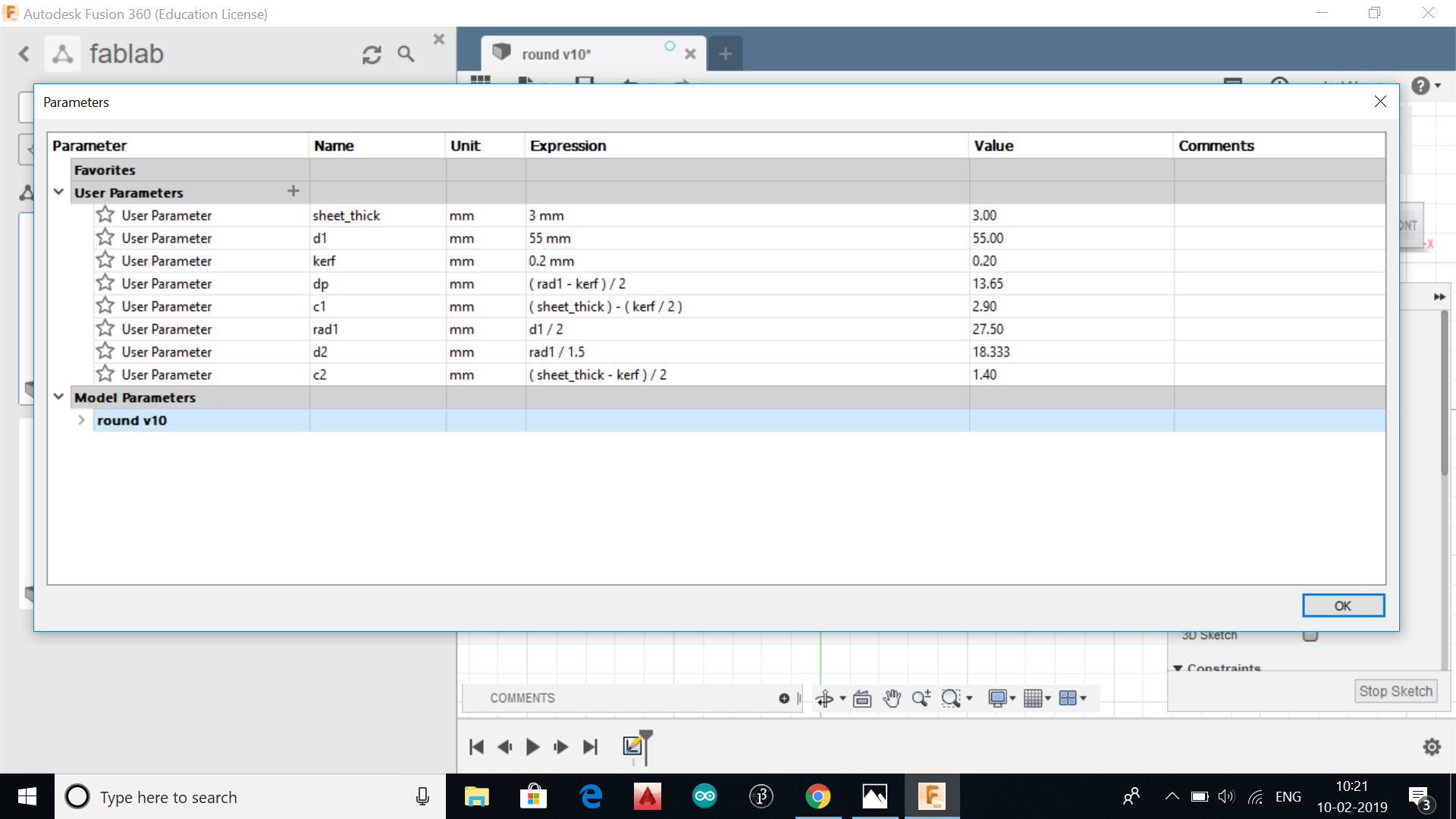
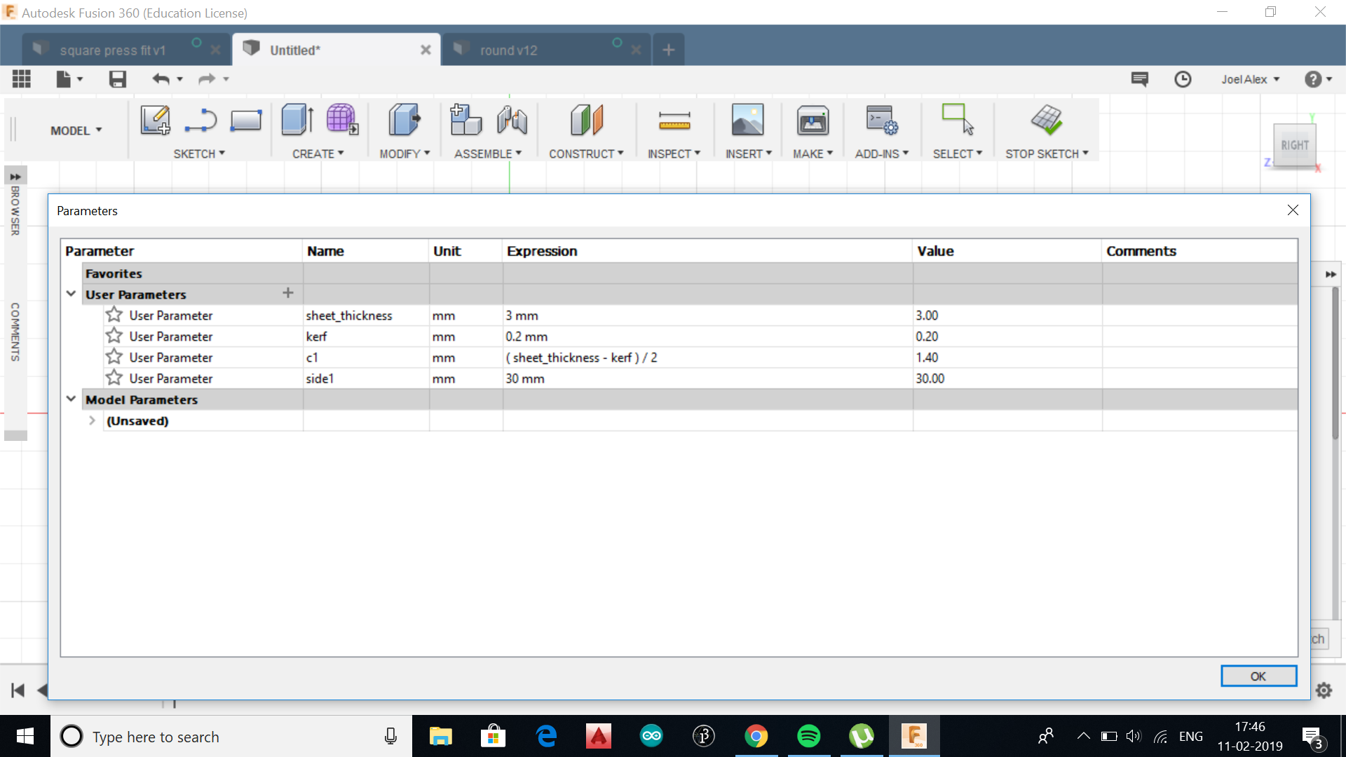
I initialised parameters such as : thick 'sheet_thickness', diameter of large circle 'd1', kerf width 'kerf', depth of slot 'dp', thickness of half slot 'c1', radius of large circle 'rad1' ,diameter of small circle 'd2'. For the moment i chose the values as below
sheet_thick = 3mm
d1 = 55mm
kerf = 0.2mm
dp = (rad1-kerf)/2
c1 = (sheet_thick)-(kerf/2)
rad1 = d1/2
d2 = rad1/1.5
c2 = (sheet_thick)-(kerf/2)
.
.
.
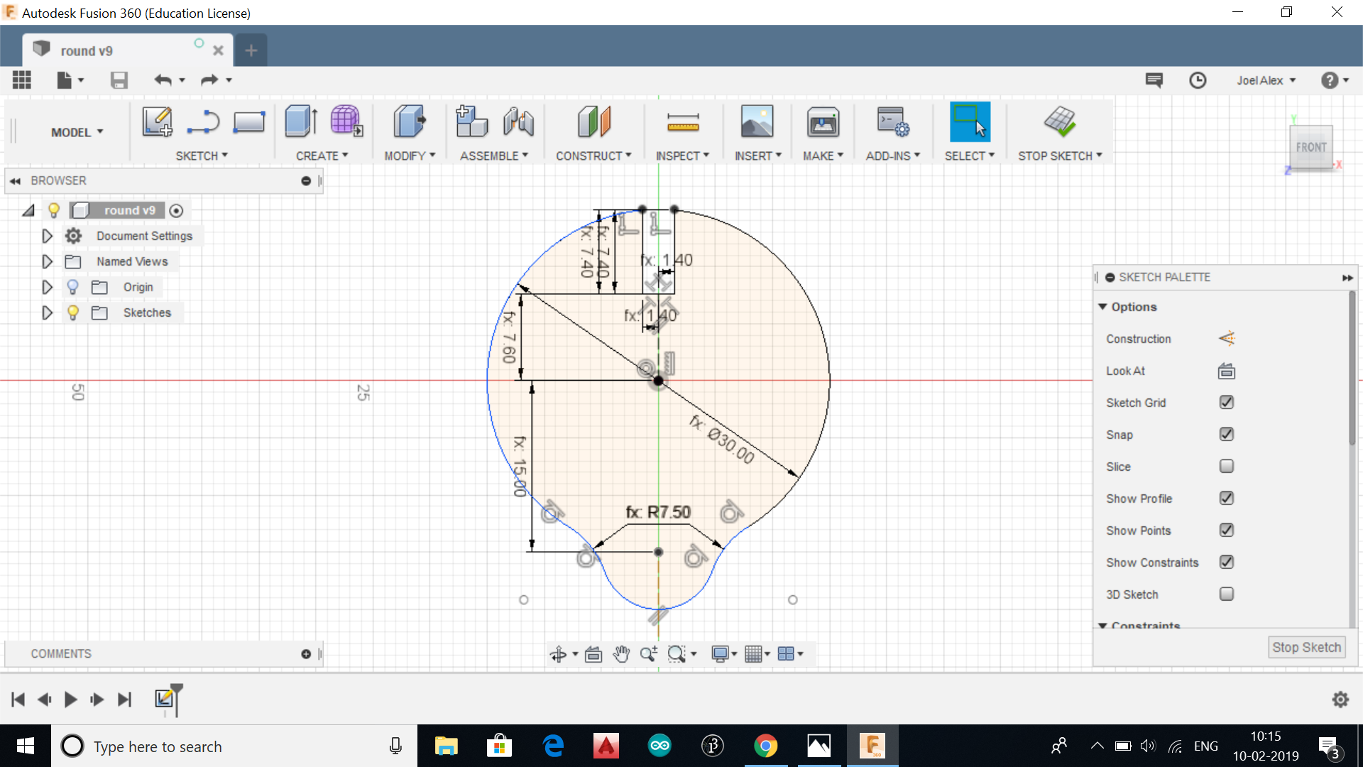
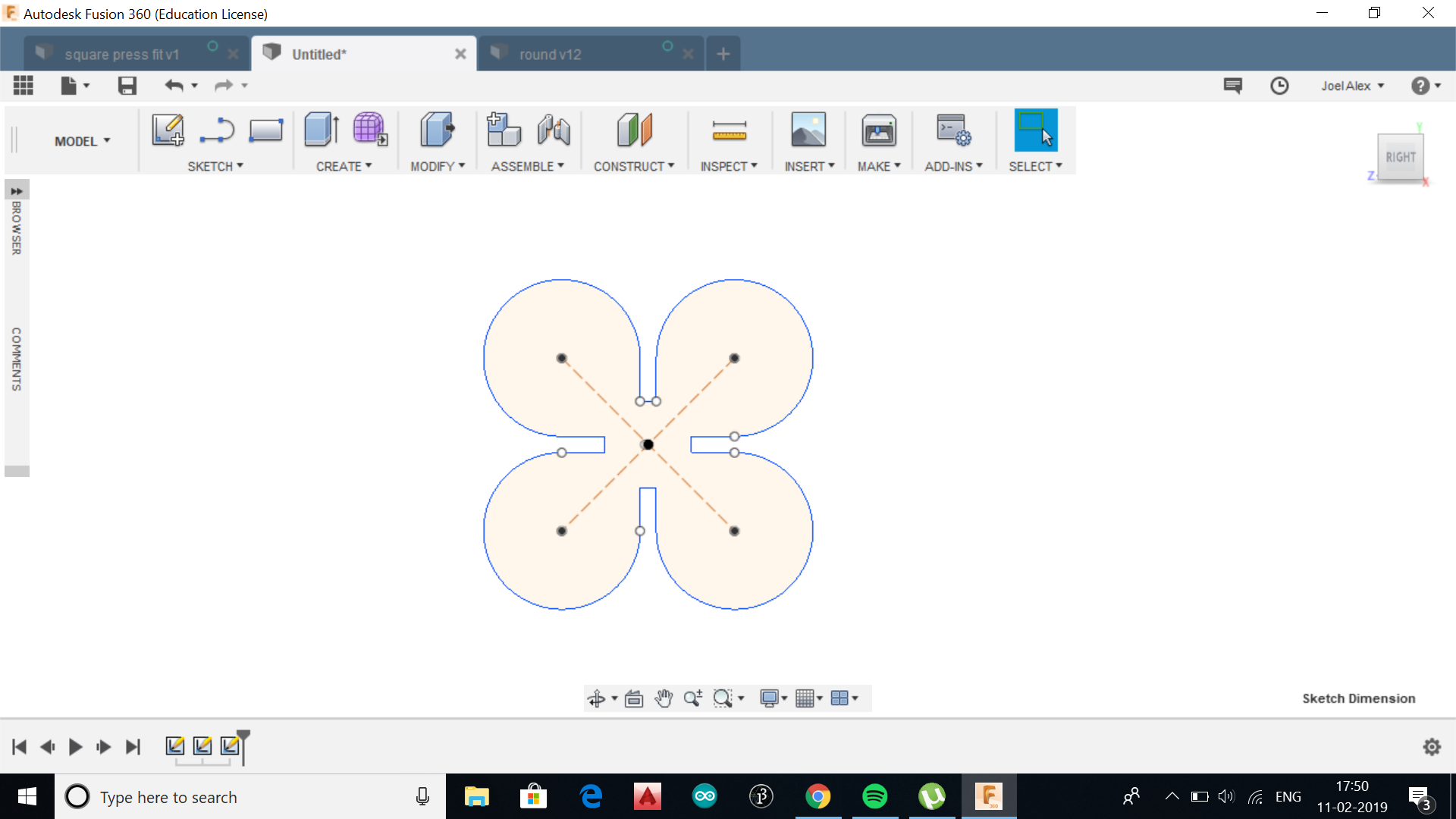
I saved the file as dxf by doing right click on sketch. The diameter of the main circle was varied in the parameter value from 30mm to 55mm and same procedure was followed to export the file as dxf for opening and editing in Inkscape as inkscape will open dxf files.
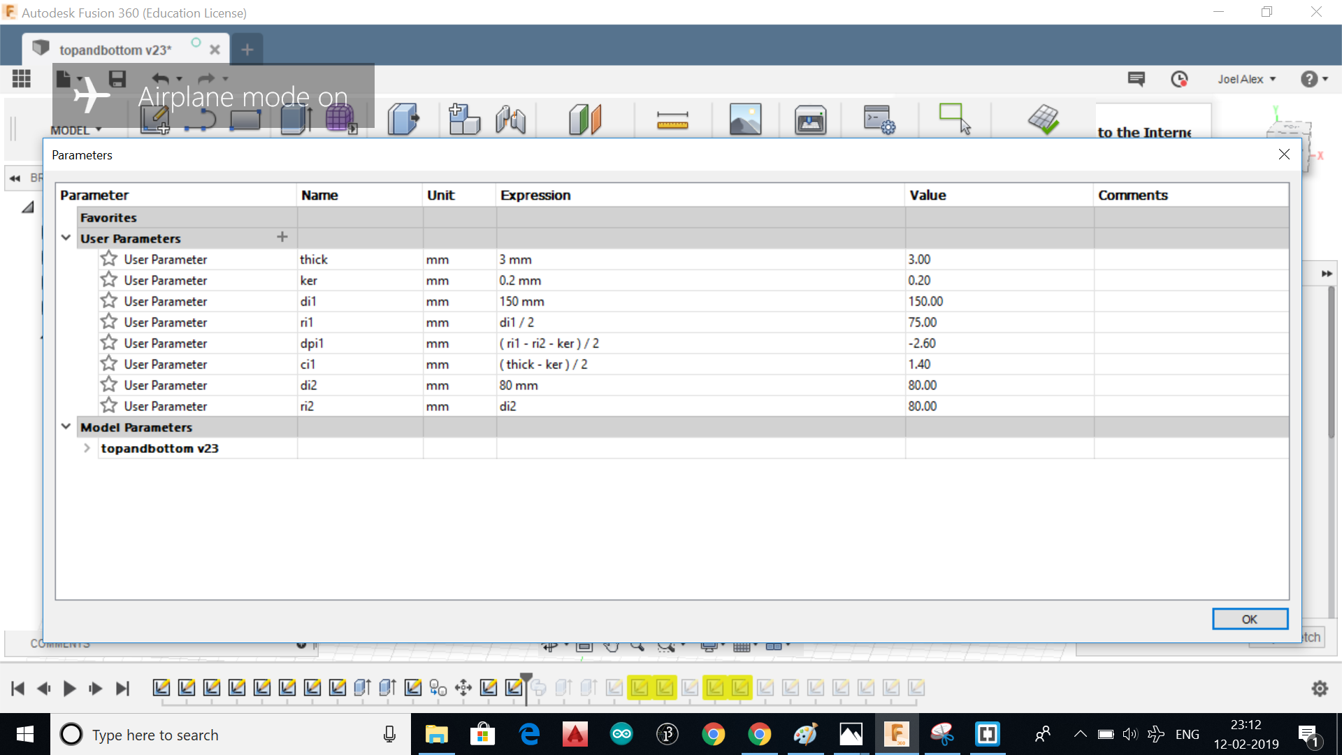
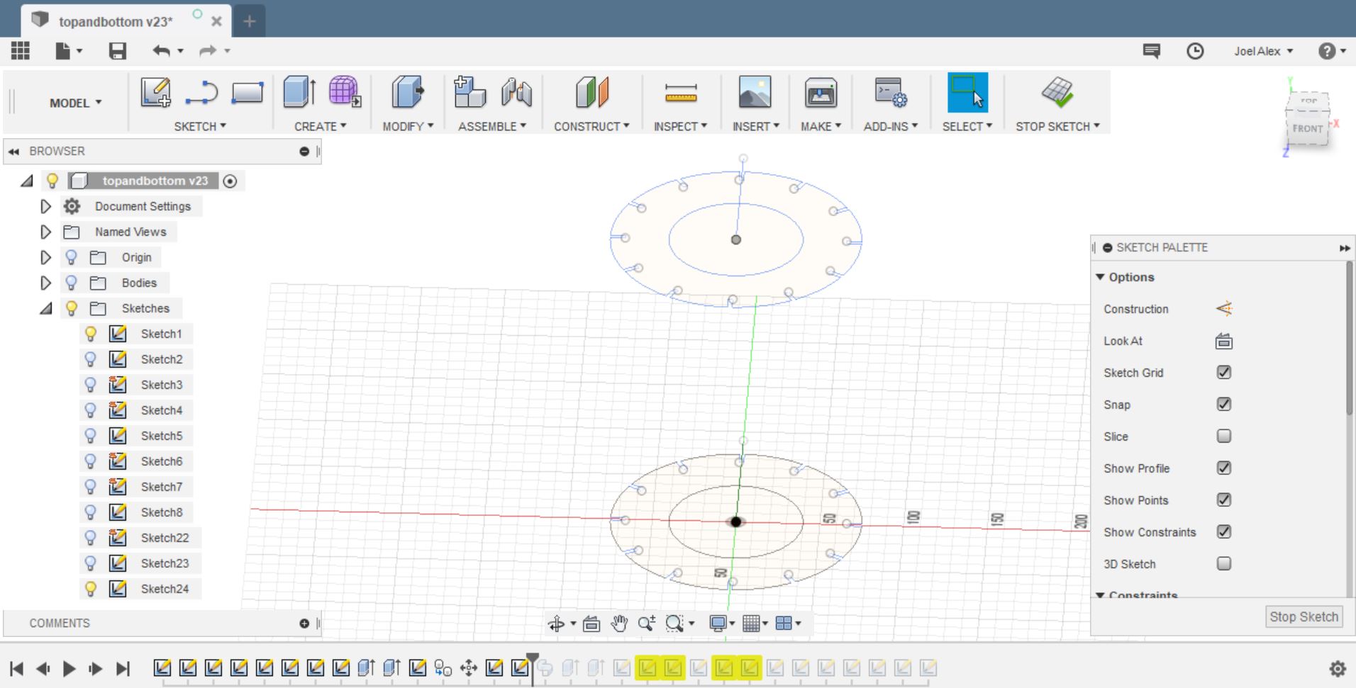
Next step was to design the sides and top of the lamp.
Another Autocad drawing file was started and the top part was designed from circle as shown in below image. The parameters were initialised. The slot size was defined as 2*c1. The tool 'circular pattern' was chosen and number of replications was chosen as 12 to accomodate the side support structure of lamp. The same circle was copied and height adjusted to the required height
.
.
.
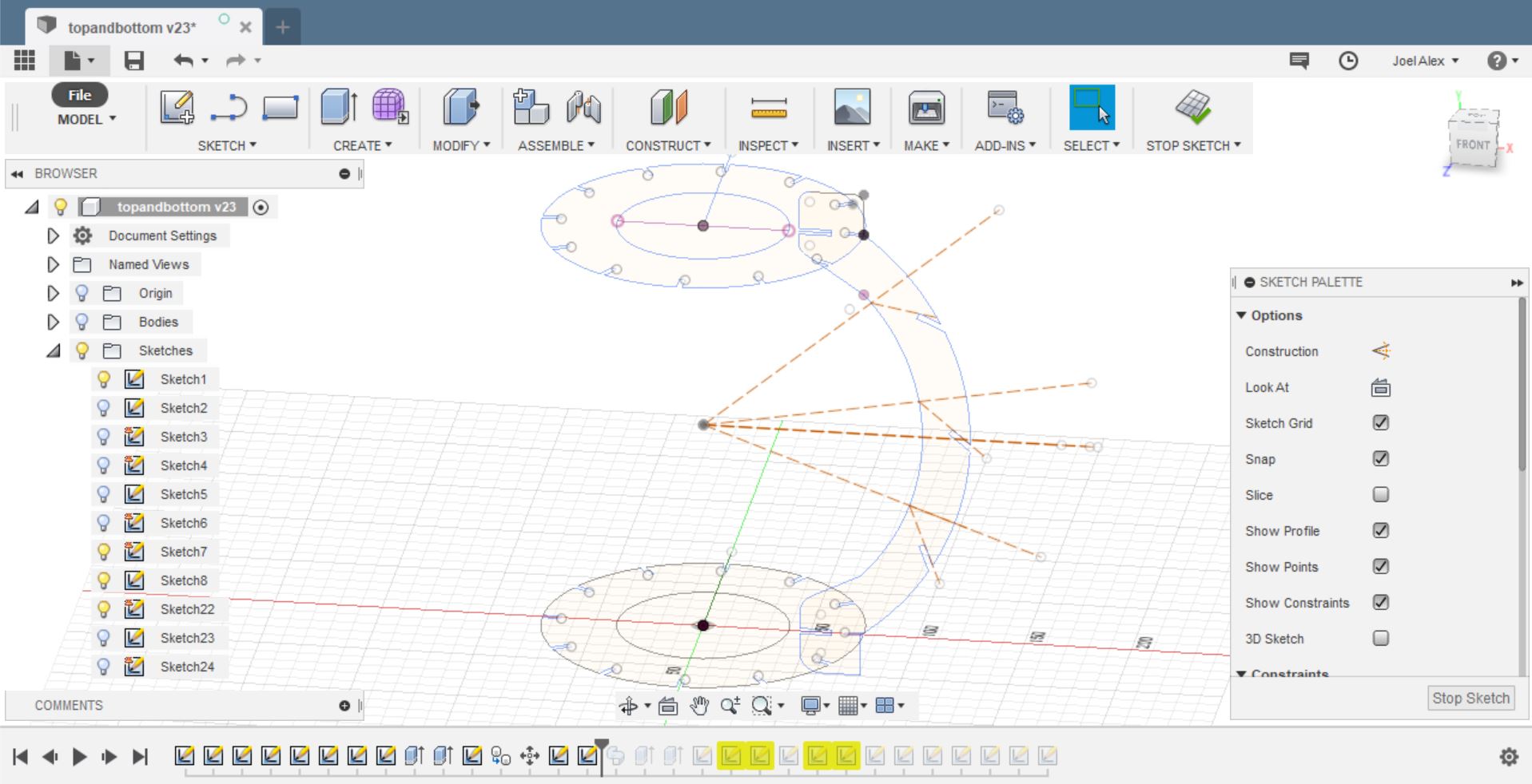
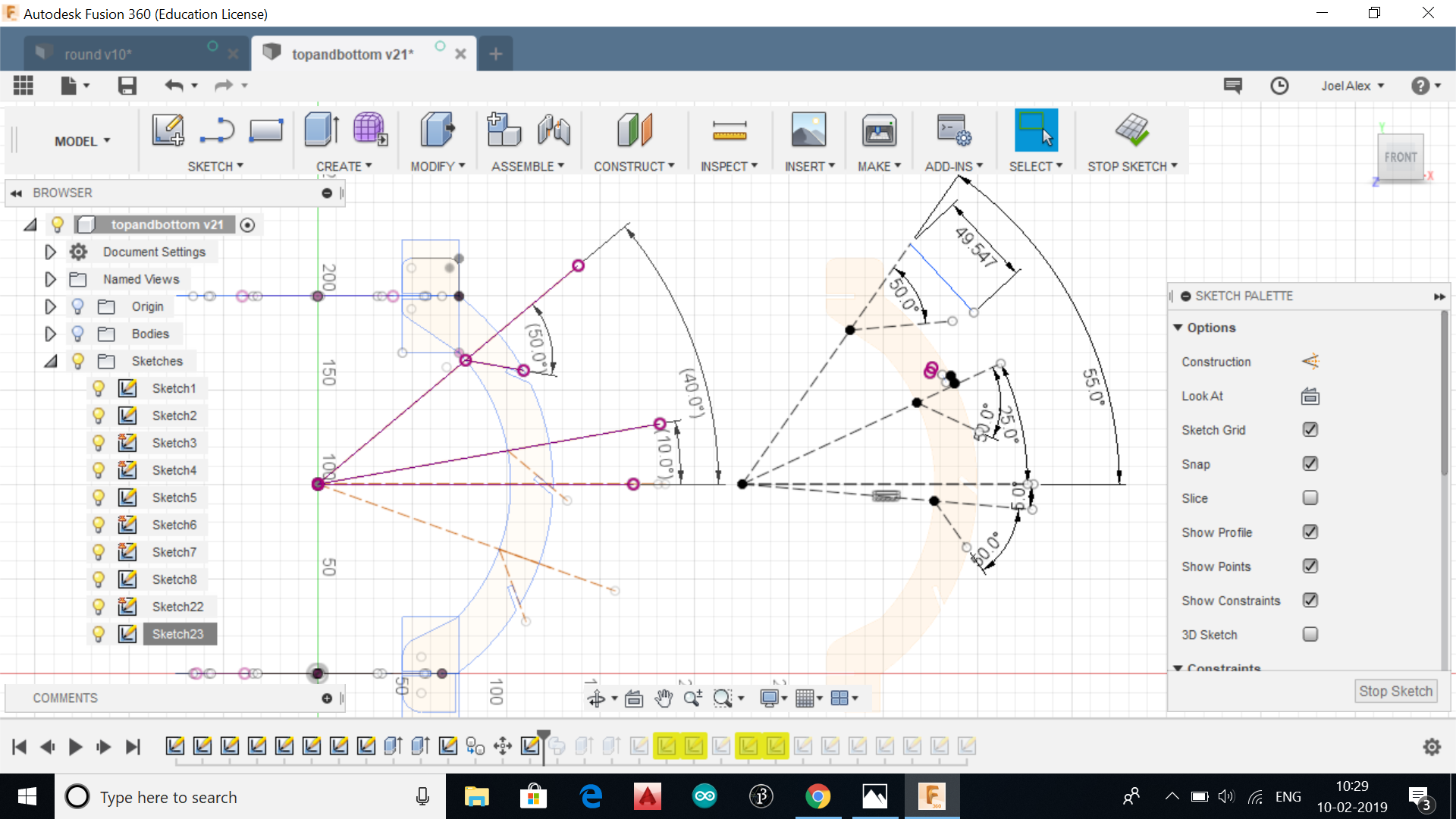
The sides of the lamps were designed next. As there is a requirement of two type of side support structure with different slot angle to accomodate a terraform design, appropriate angles of cutting was given in the sides as below.
.
.
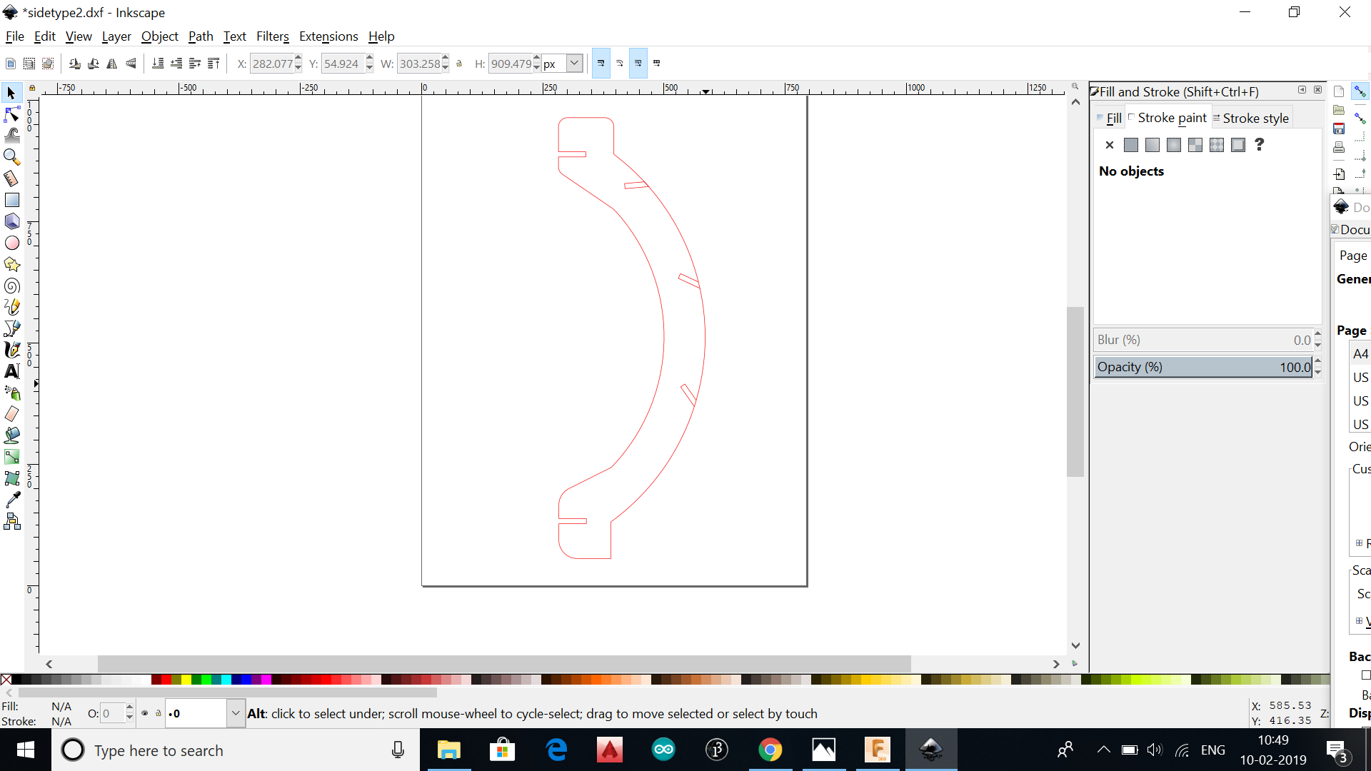
After the designing as above, the sketches were saved as seperate dxf files by doing right click on each sketches and clicking 'save as dxf'.Theses dxf files were then opened in Inkscape inorder to adjust fill and stroke value for laser cutting as below:
.
.
.
.
.
.
.
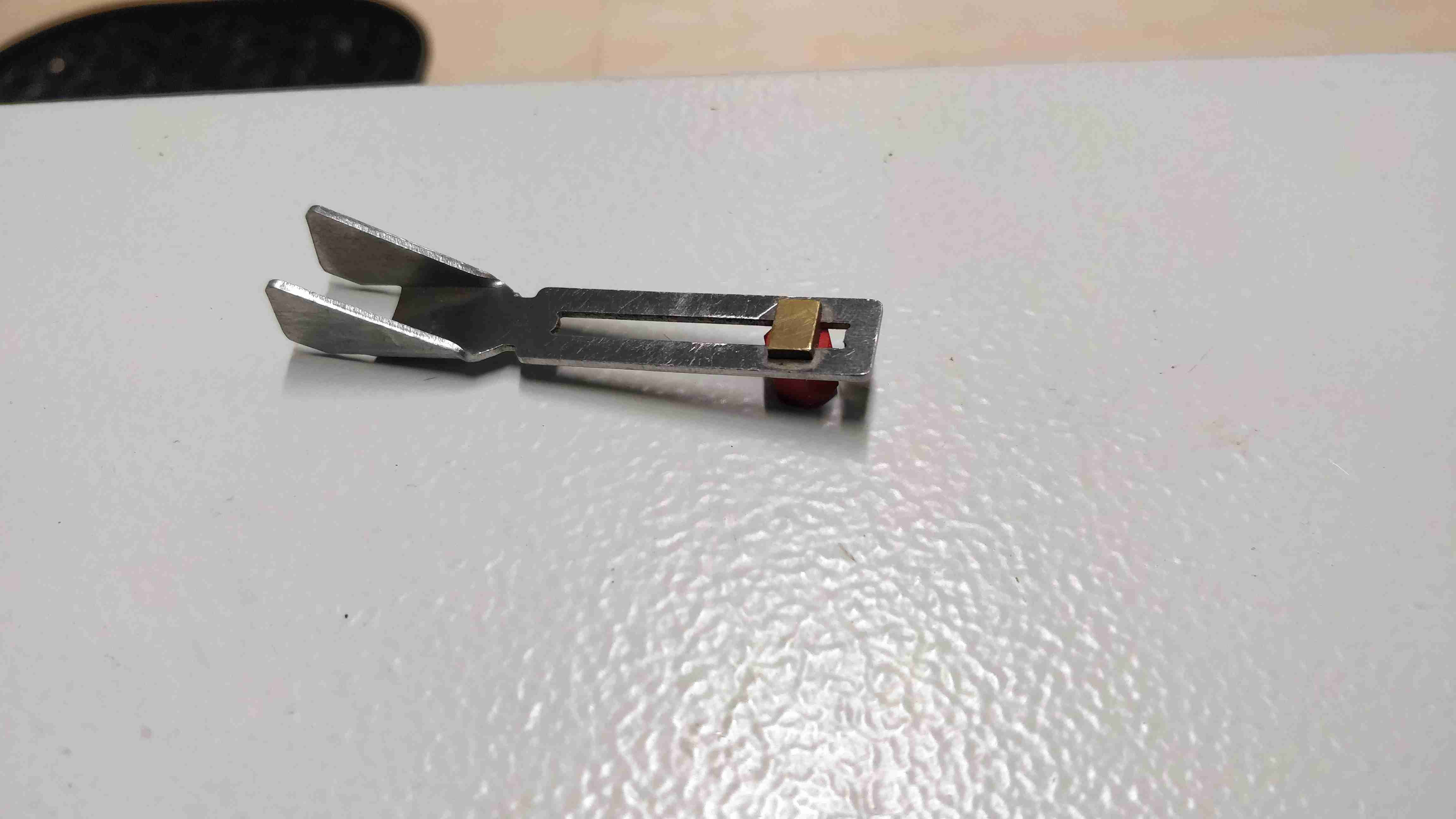
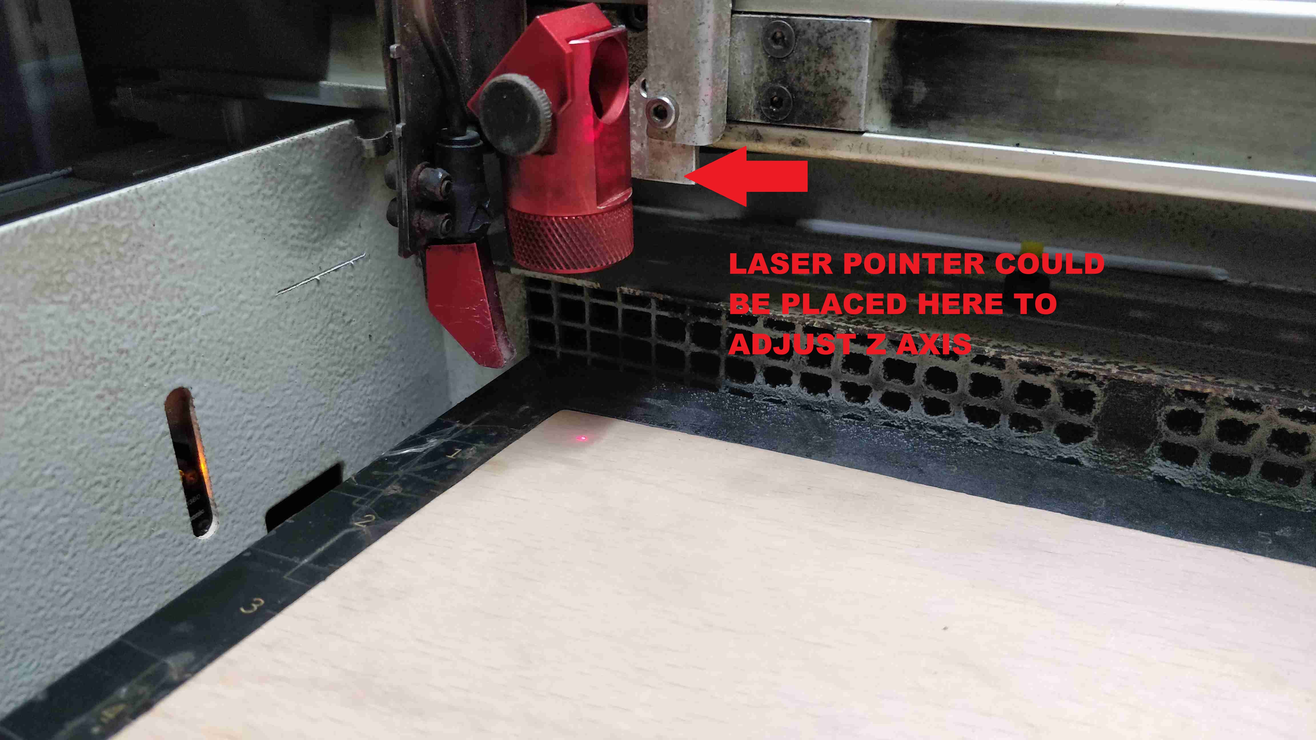
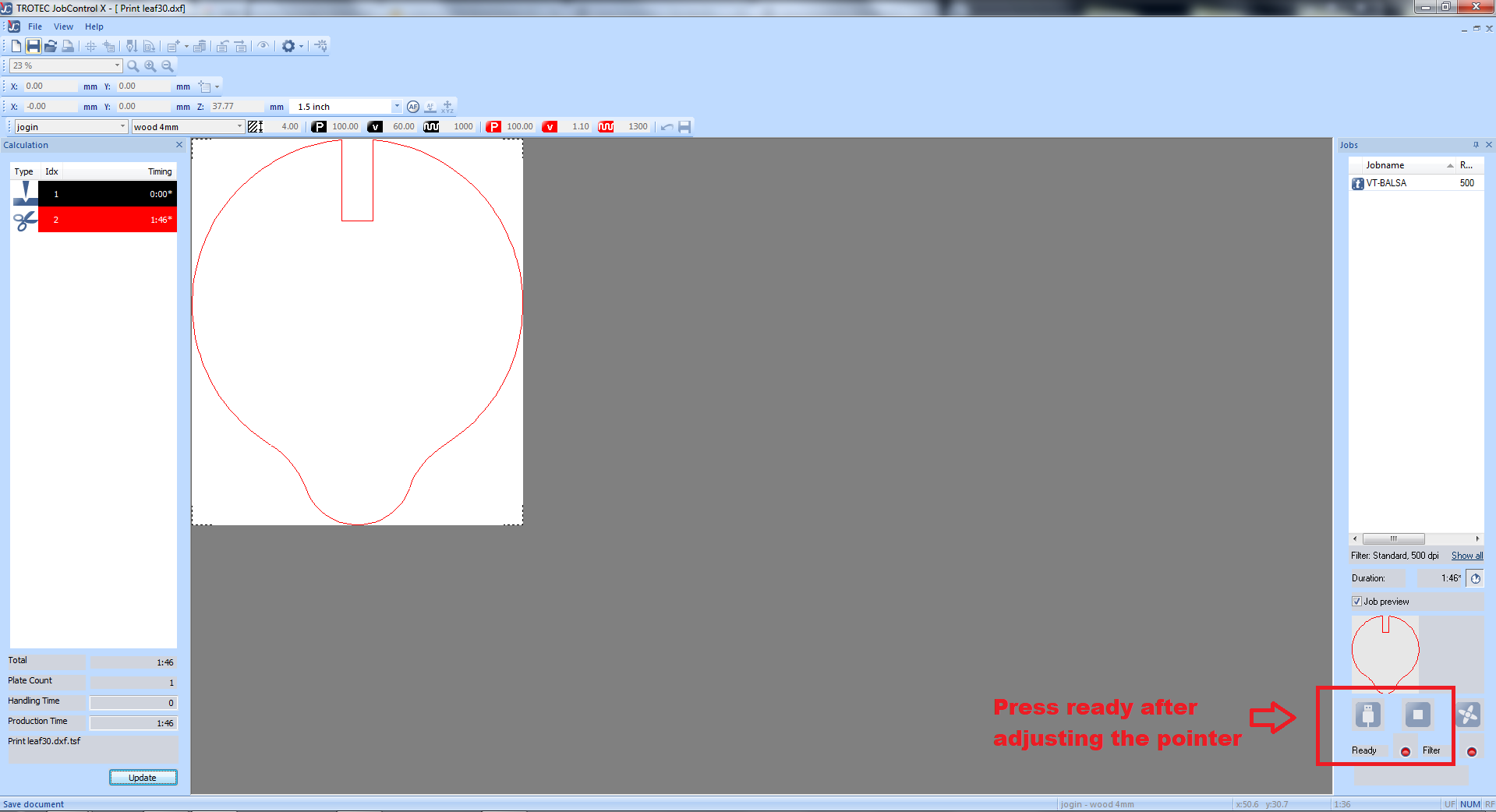
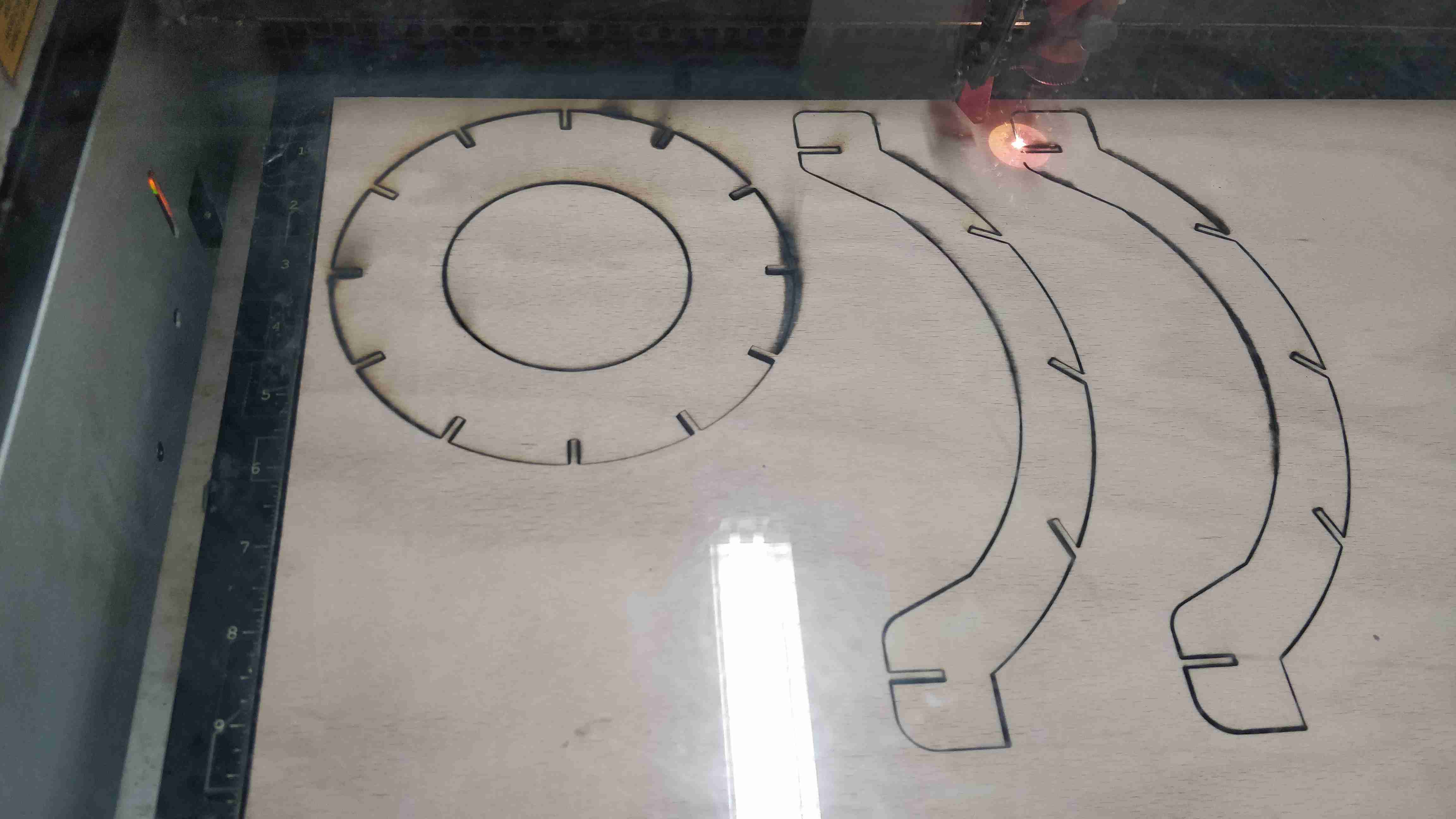
Whole the files were processed like this, 4mm plywood was placed in the lasercutter and the laser was focused using the focusing tool by adjusting the height. The laser pointer was placed at side of the plywood to start cutting. After pressing start ,the laser cutter starts to cut the plywood .Make sure to engage the air filter machine before starting to cut the parts. Every files could be cut using the same steps
.
.
.
.
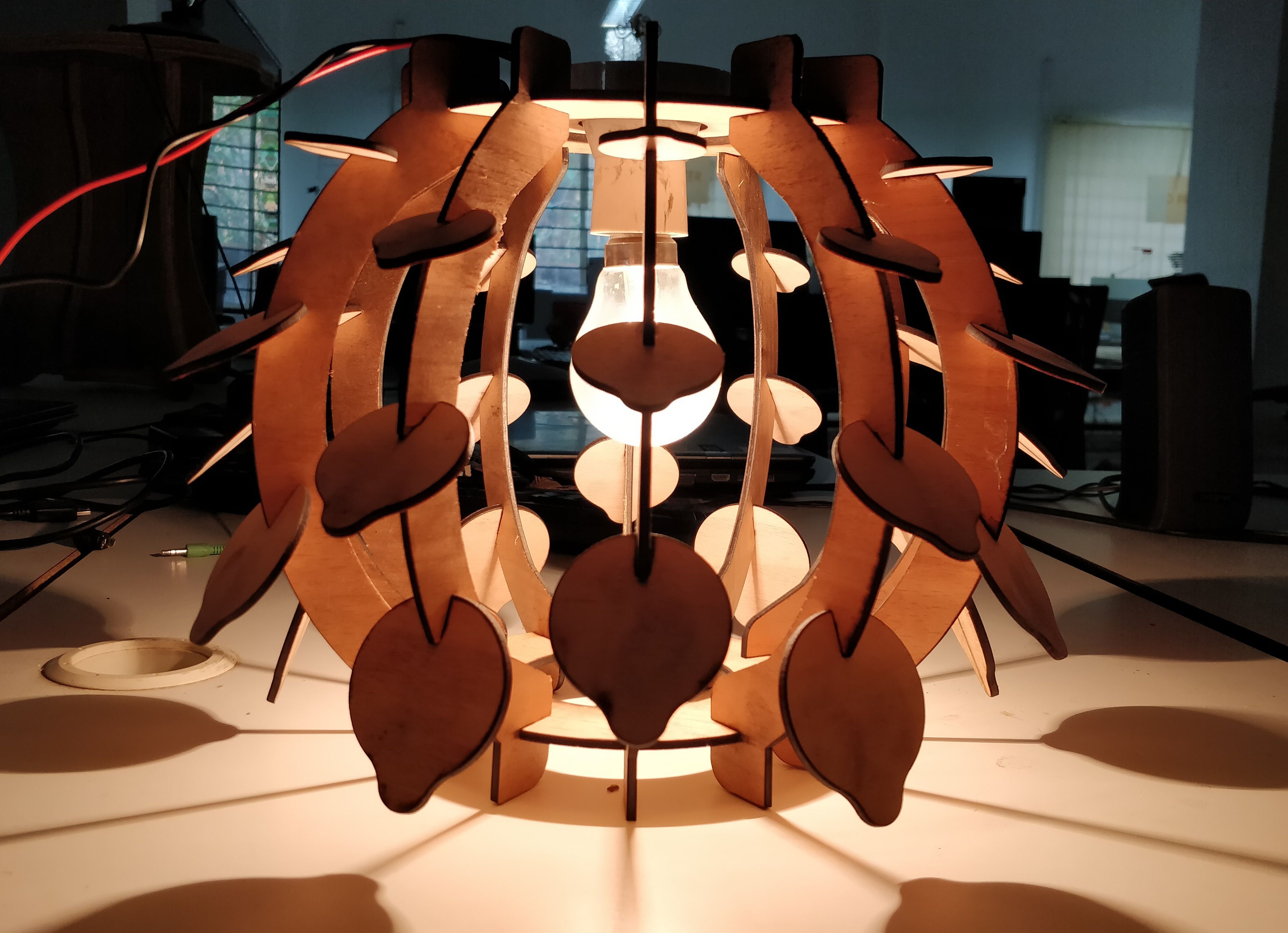
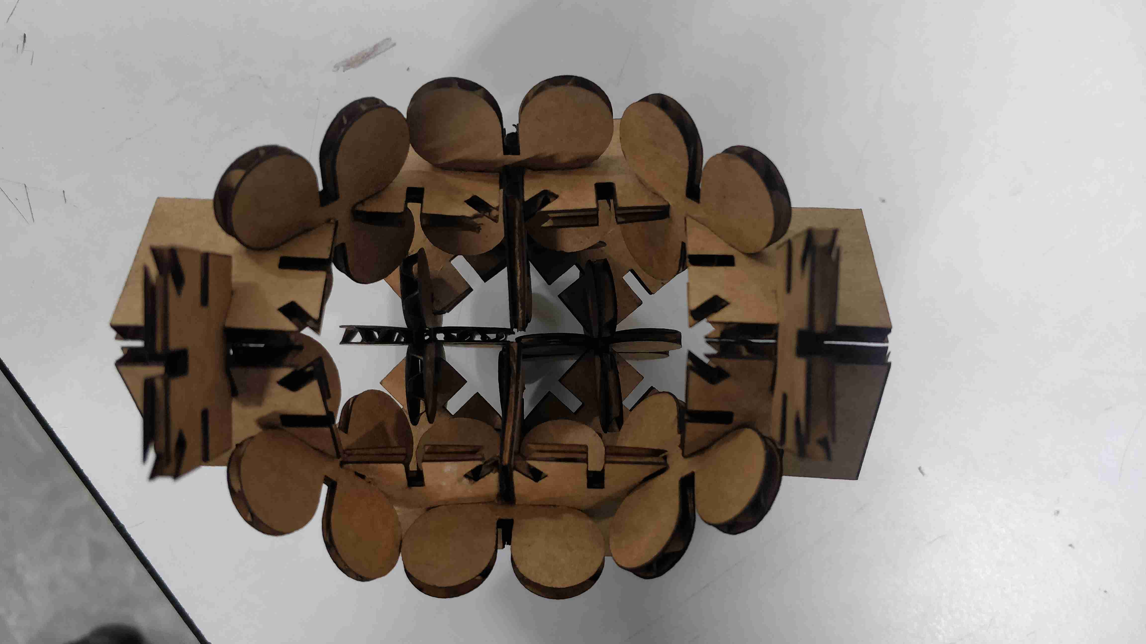
Whole the parts including leaves, top ,bottom circle,side support structures were laser cut and the assembled to obtain a lamp holder. And i call it THE PARAMETRIC LAMP
.
.
.
.
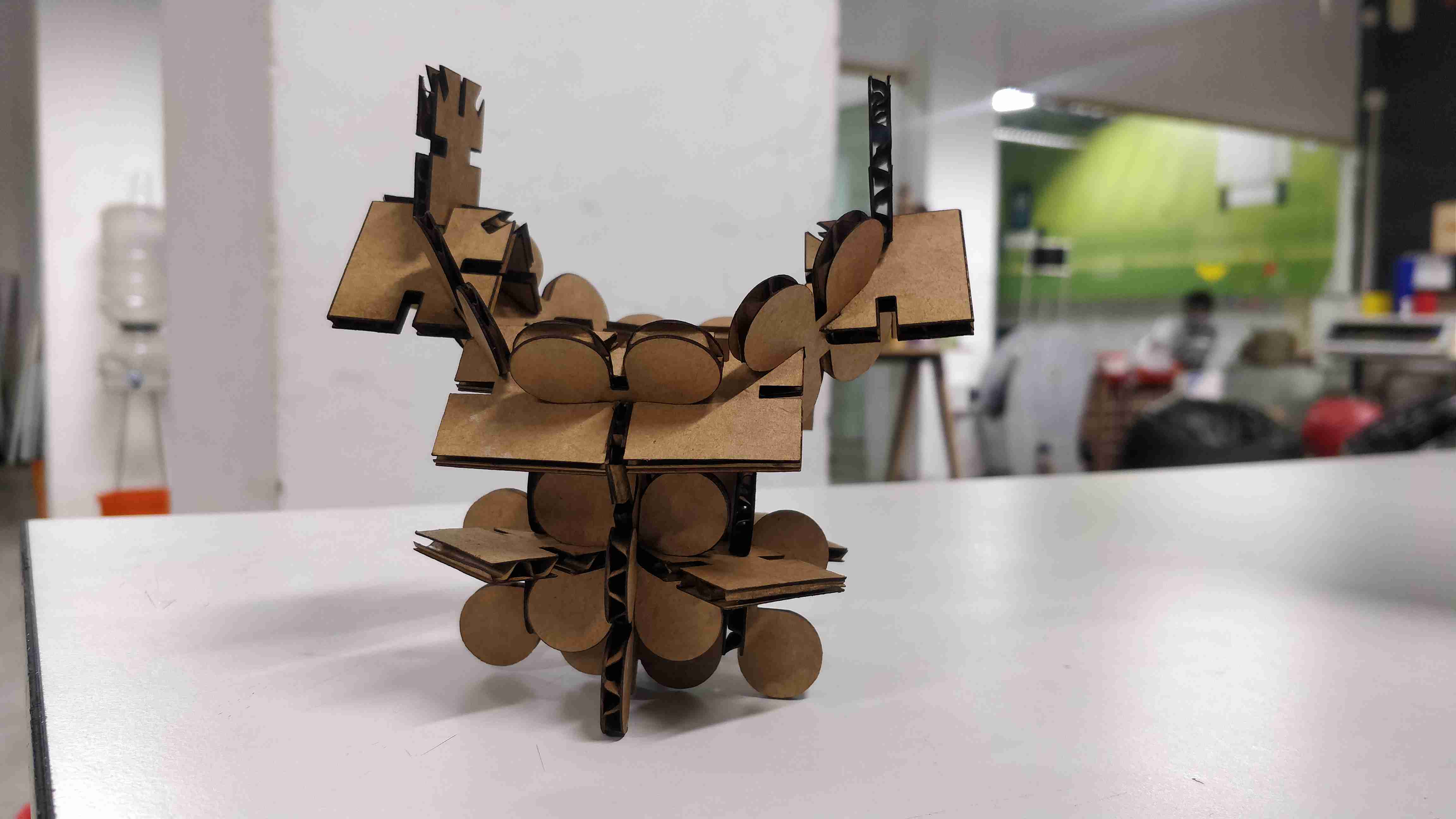
As usual i started by setting the parameters like kerf,sheet thickness, used autocad fusion 360 to design the same. Two modules were designed as below:
.
.
.
.
.png)
.
.png)
.
The designs were added to the tasks of laser cutter and was cut and different designs were obtained from the same construction kit
.
.
.
.
.
.
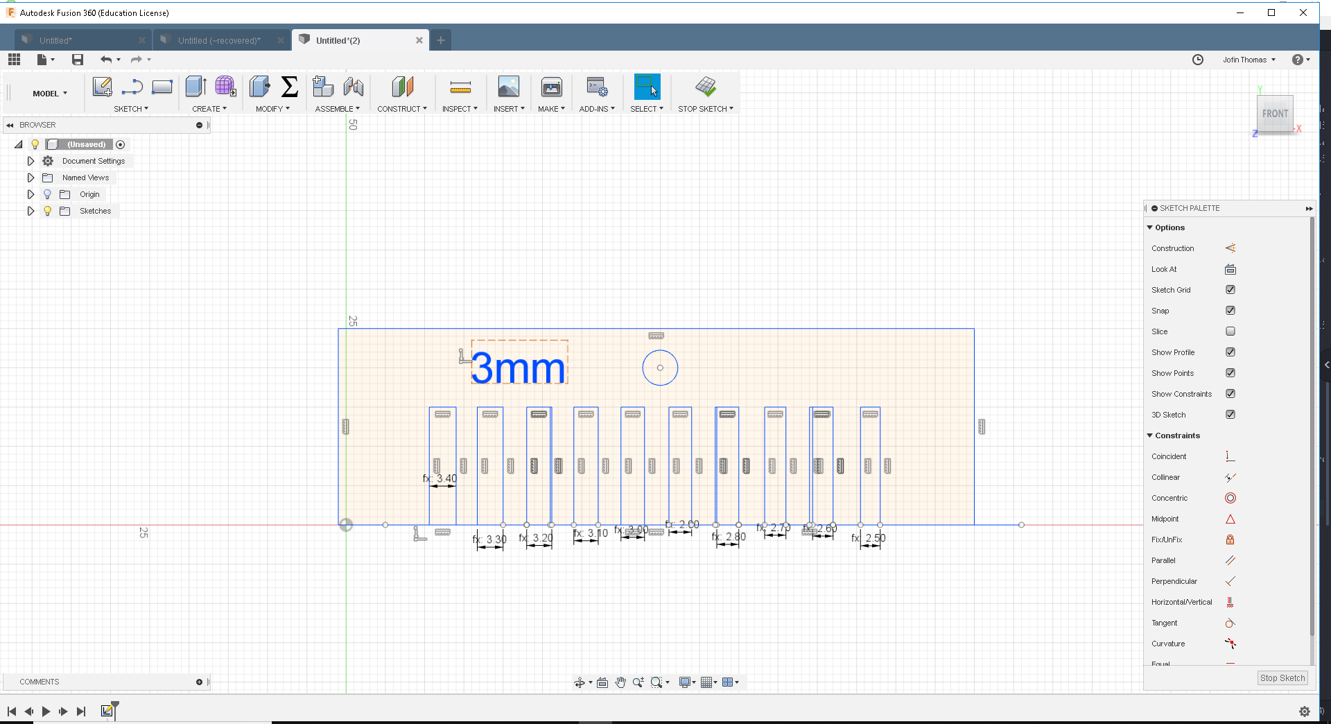
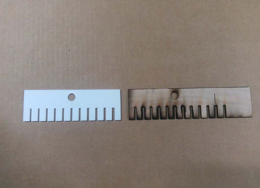
The group assignment was to design a kerf scale inorder to undertand the perfect fit dimension.We designed a scale ranging from 2.5mm to 3.4mm for the 3mm plywood and 3mm acrylic sheet as below
The kerf scales made in plywood and acrylic sheet was matched with 3mm plywood and 3mm acrylic piece. The perfect match points of the joint was found to be at 2.8mm.The Kerf value of plywood was found out to be 0.2mm
Cutting Parameters
Engraving Parameters
.
.