Input devices
Assignments
Input Devices
In computing, an input device is a piece of computer hardware equipment used to provide data and control signals to an information processing system such as a computer or information appliance. Examples of input devices include keyboards, mouse, scanners, digital cameras and joysticks.
So in this week I have desided to make a magnetic fiels detector. I am going to use a "Hall Effect sensor" that.
Hall Effect Sensor
A Hall effect sensor is a device that is used to measure the magnitude of a magnetic field. Its output voltage is directly proportional to the magnetic field strength through it. Hall effect sensors are used for proximity sensing, positioning, speed detection, and current sensing applications.
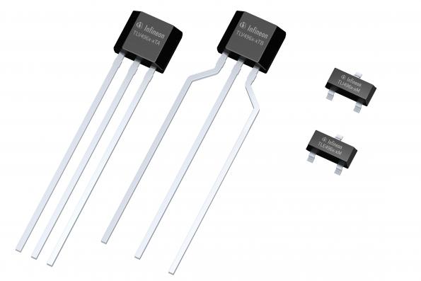
You can download the datasheet from here
Hall effect
If an electric current flows through a conductor in a magnetic field, the magnetic field exerts a transverse force on the moving charge carriers which tends to push them to one side of the conductor. This is most evident in a thin flat conductor as illustrated. A buildup of charge at the sides of the conductors will balance this magnetic influence, producing a measurable voltage between the two sides of the conductor. The presence of this measurable transverse voltage is called the Hall effect after E. H. Hall

Note that the direction of the current I in the diagram is that of conventional current, so that the motion of electrons is in the opposite direction. That further confuses all the "right-hand rule" manipulations you have to go through to get the direction of the forces.
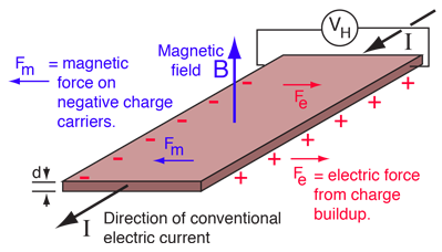
The Hall voltage is given by
VH = IB/ned
where n = density of mobile charges and e = electron charge.
The Hall effect can be used to measure magnetic fields with a Hall probe.
PCB Design
I started Design with ATtiny45 with Autodesk EAGLE. I learned PCB design in ELECTRONICS DESIGN week-7 . Addionally I hav added a "Hall Effect Sensor".For this circuit I did't used external clock because my application will run smoothly on internal 8 mhz clock.
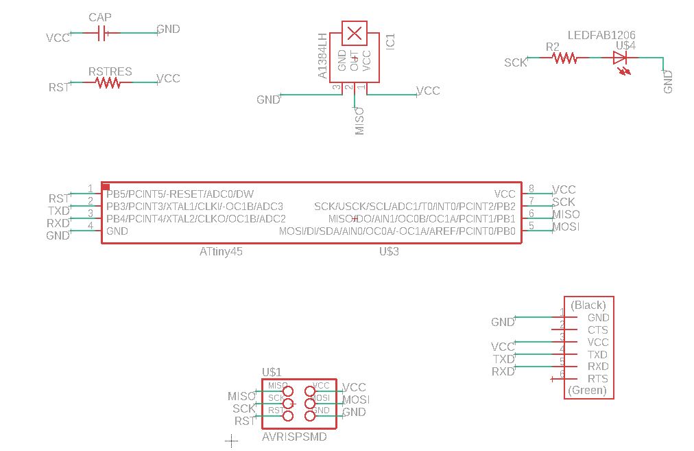
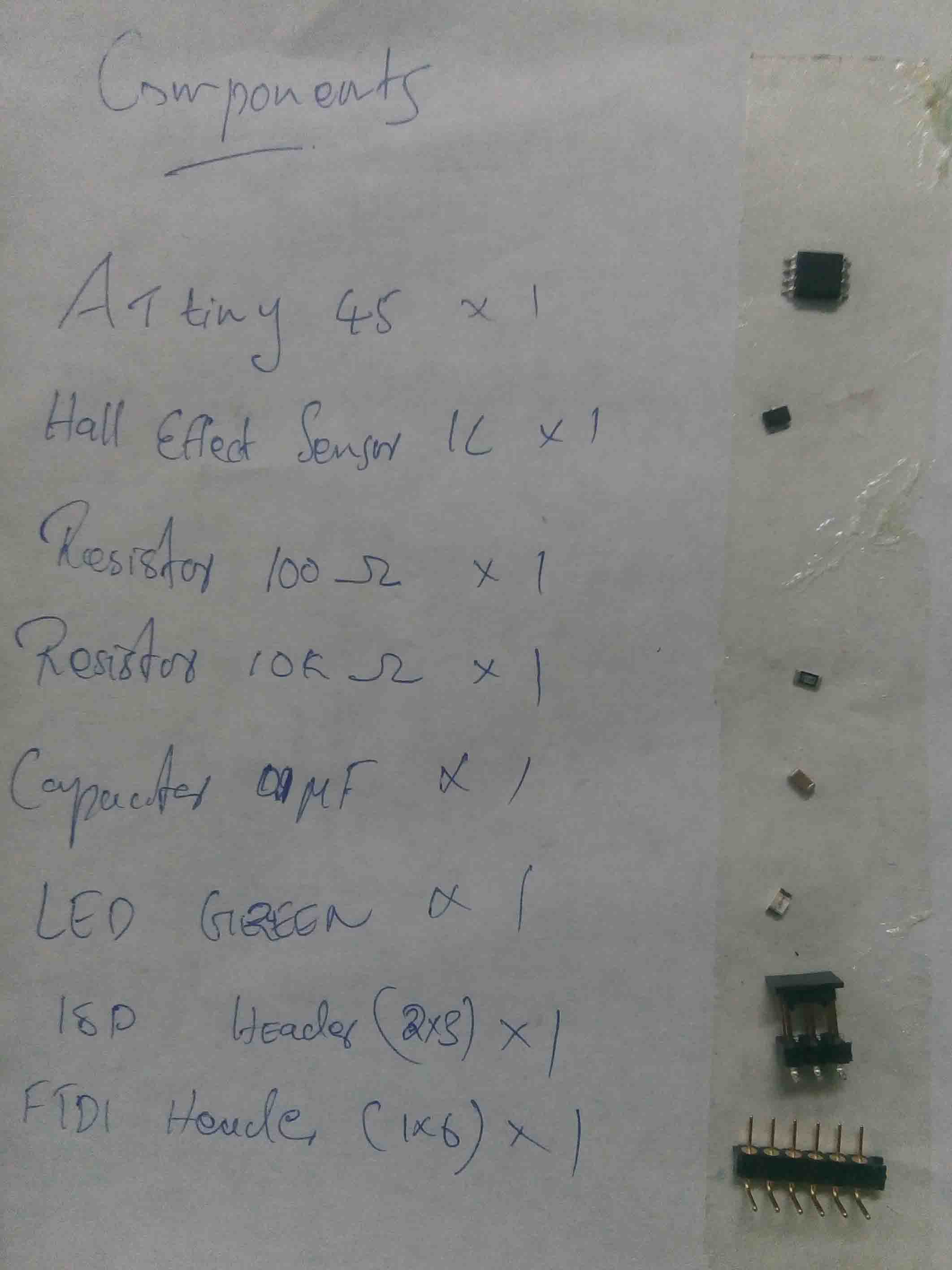
Components
After finishing the circuit in schematics, I move to the PCB part. I didnt use "Auto-routing".
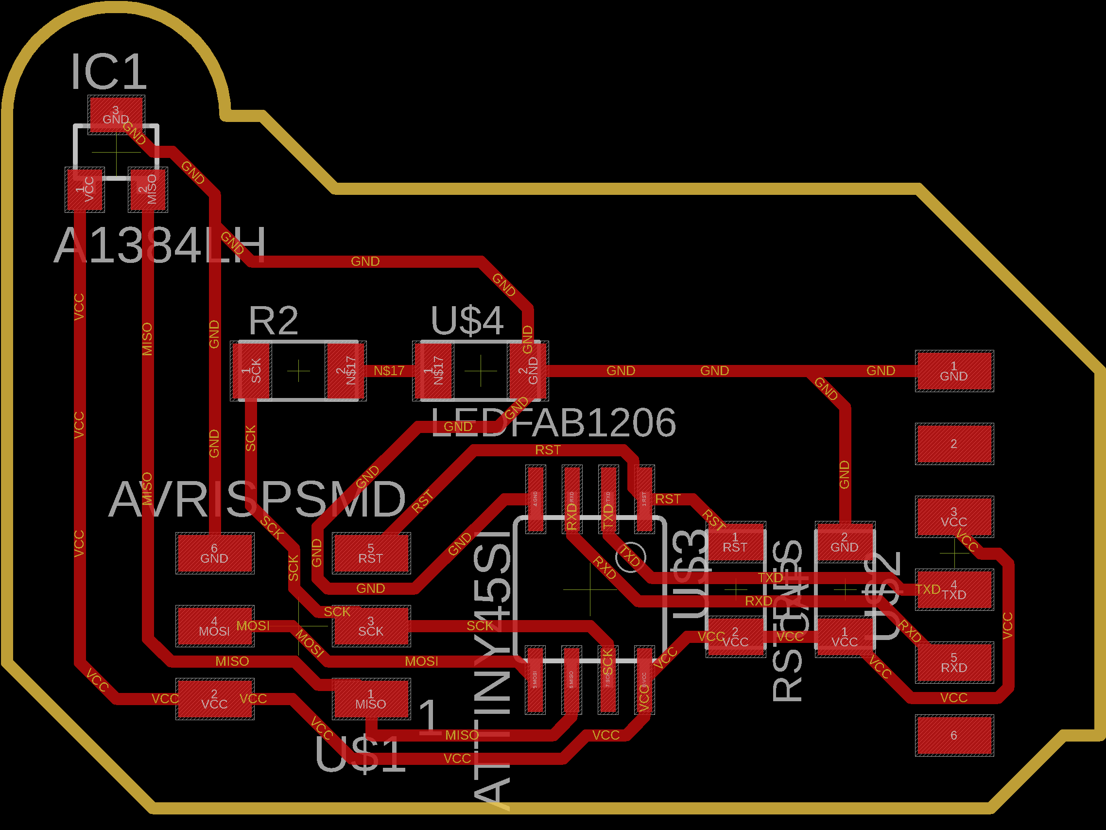
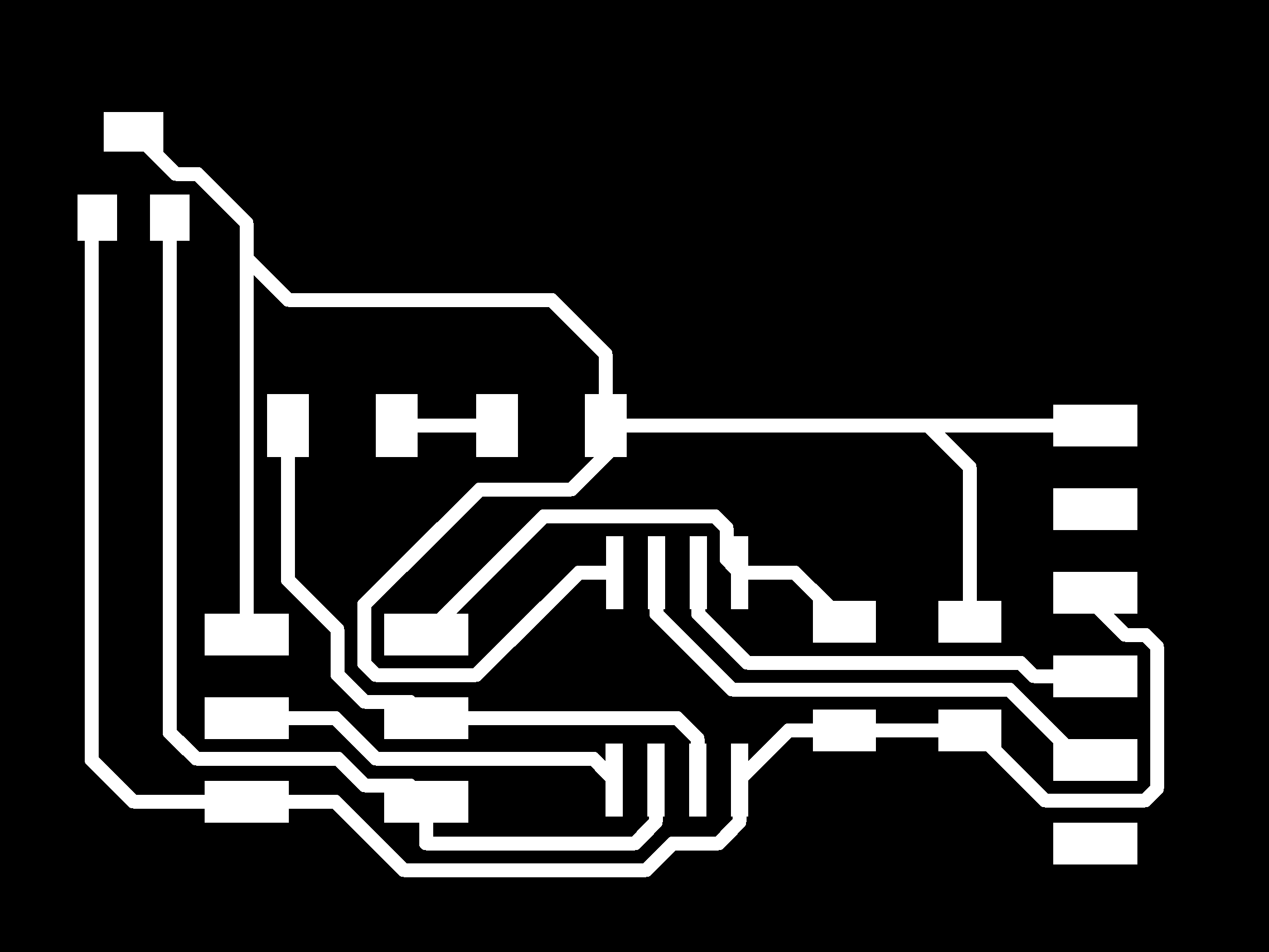
I exported Mill , drill and Cut images and Monochrome.
Mill traces
Drill cuts

You can download the files here
PCB Milling
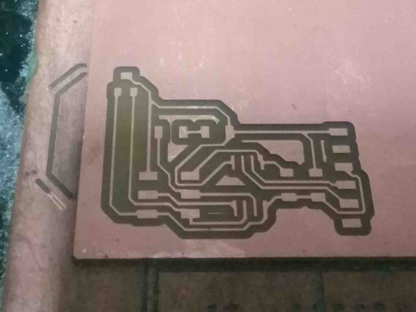
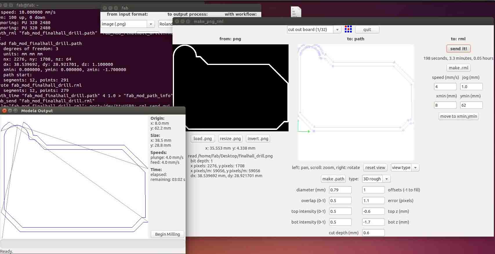
As we did in previous weeks, I opened fab mods and add pcb layout. First I started with mill traces
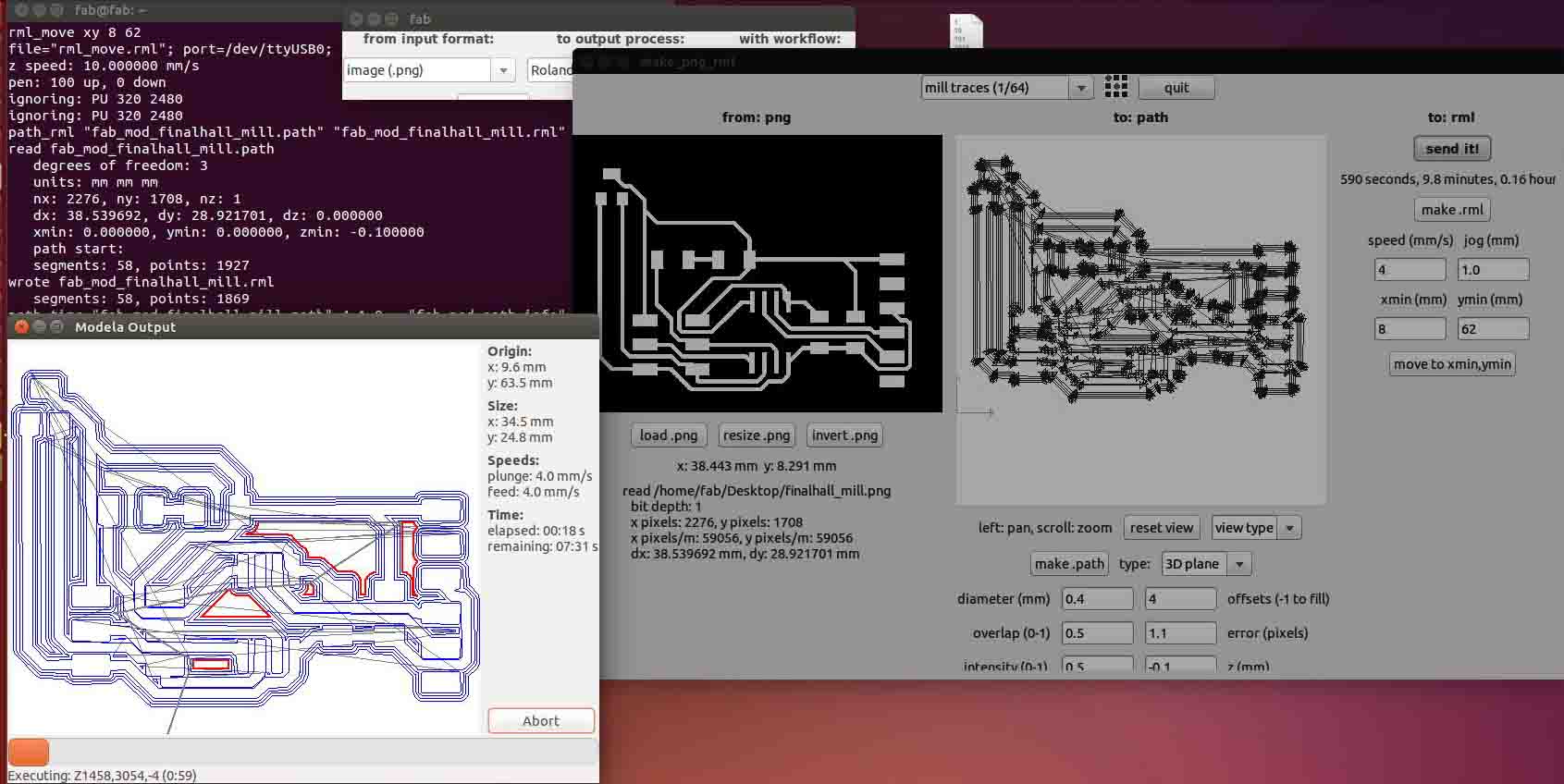
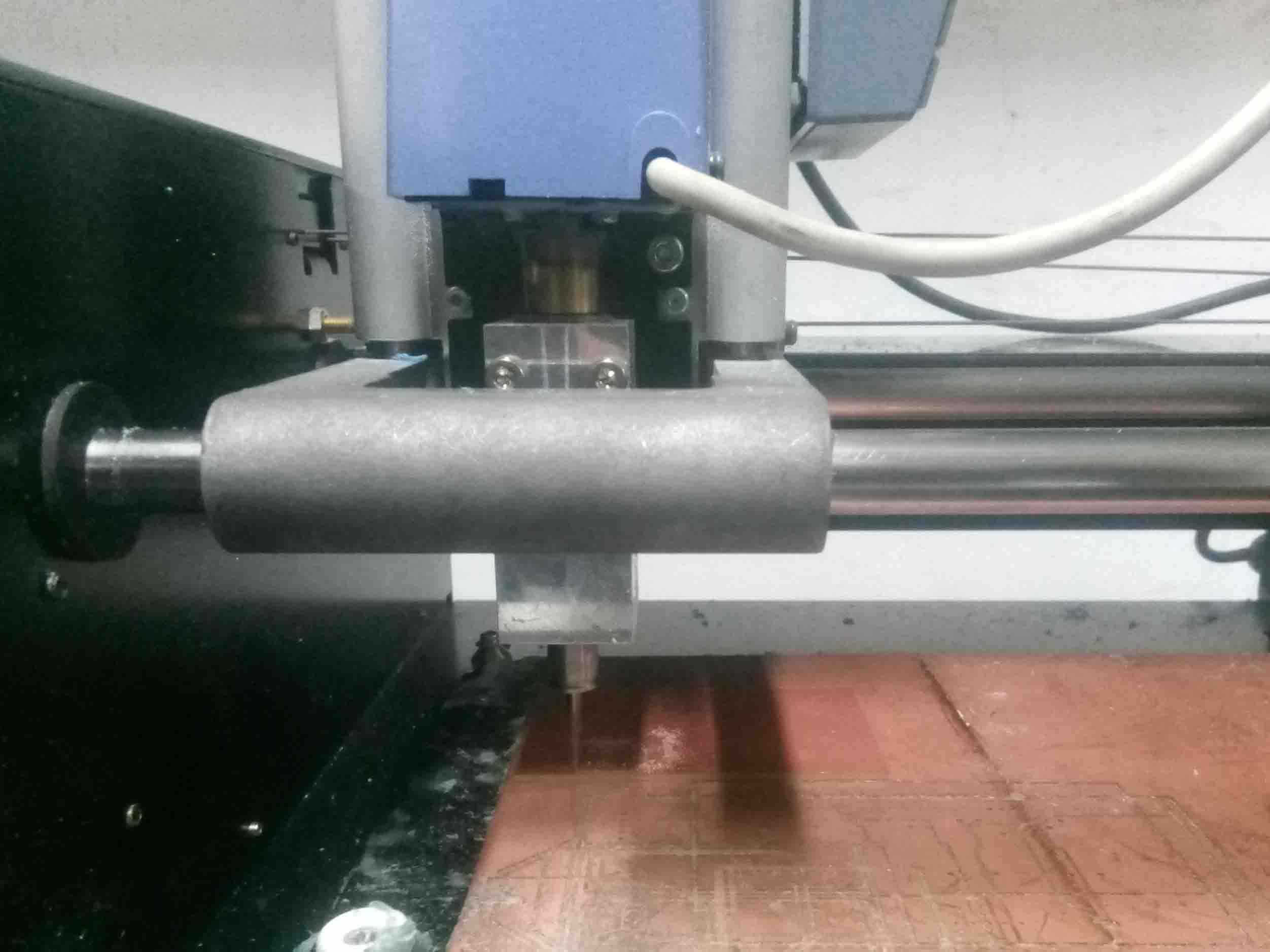
I used a 1/64 inch v-bit to mill traces. The machine started milling...
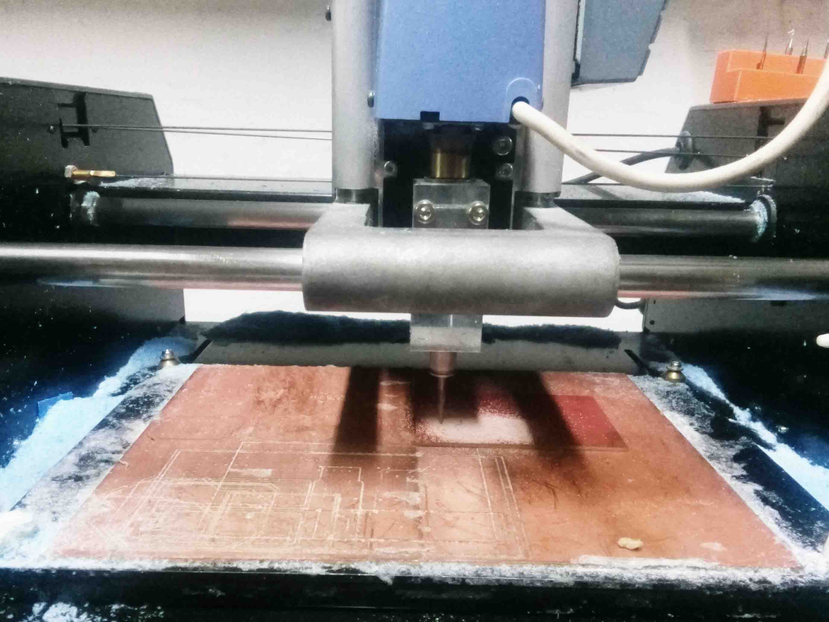
It looked like this after milling
I load the drill cut trace into the fab modes and prepared G-Code
I repeated the same process with the drilling case. This time I used 1/32 inch bit.
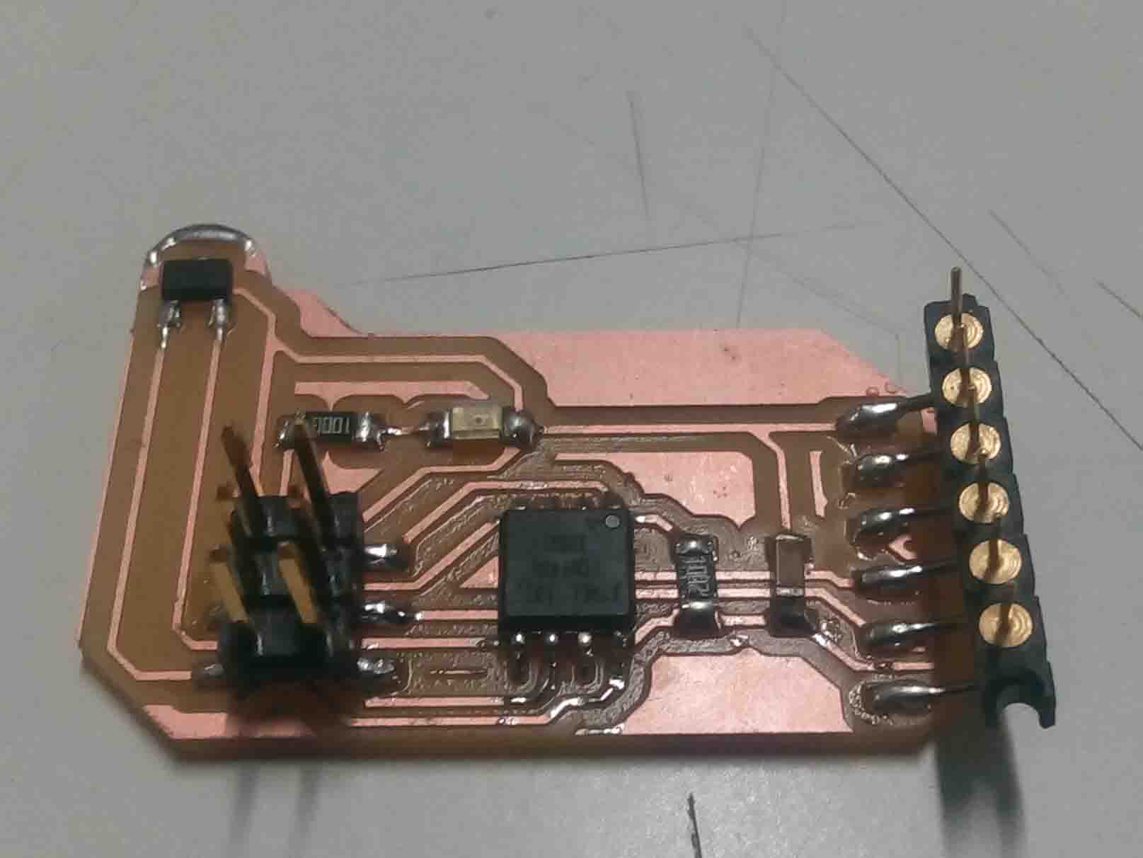
Here is the finished board
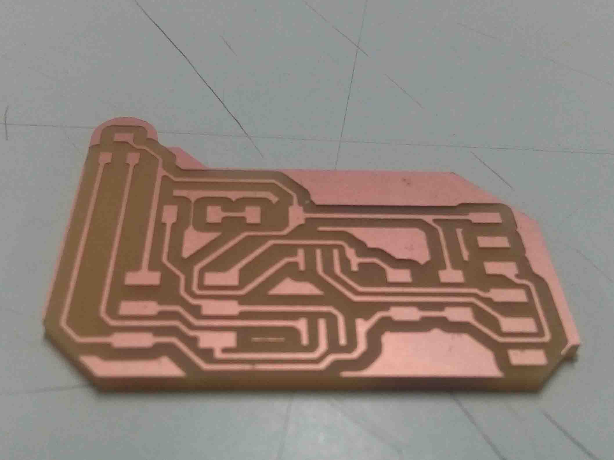
Now the PCB is ready to be soldered. So let's solder...
Soldering
Like I dis in previous weeks, I take the components from the inventory and soldered them one by one to the board.
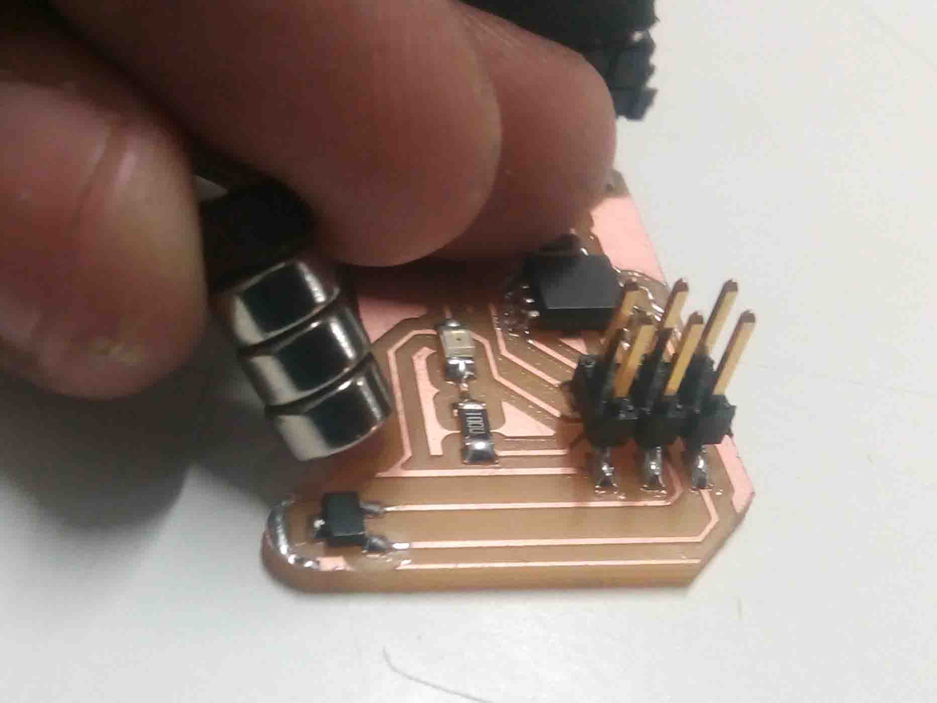
I soldered them to the board
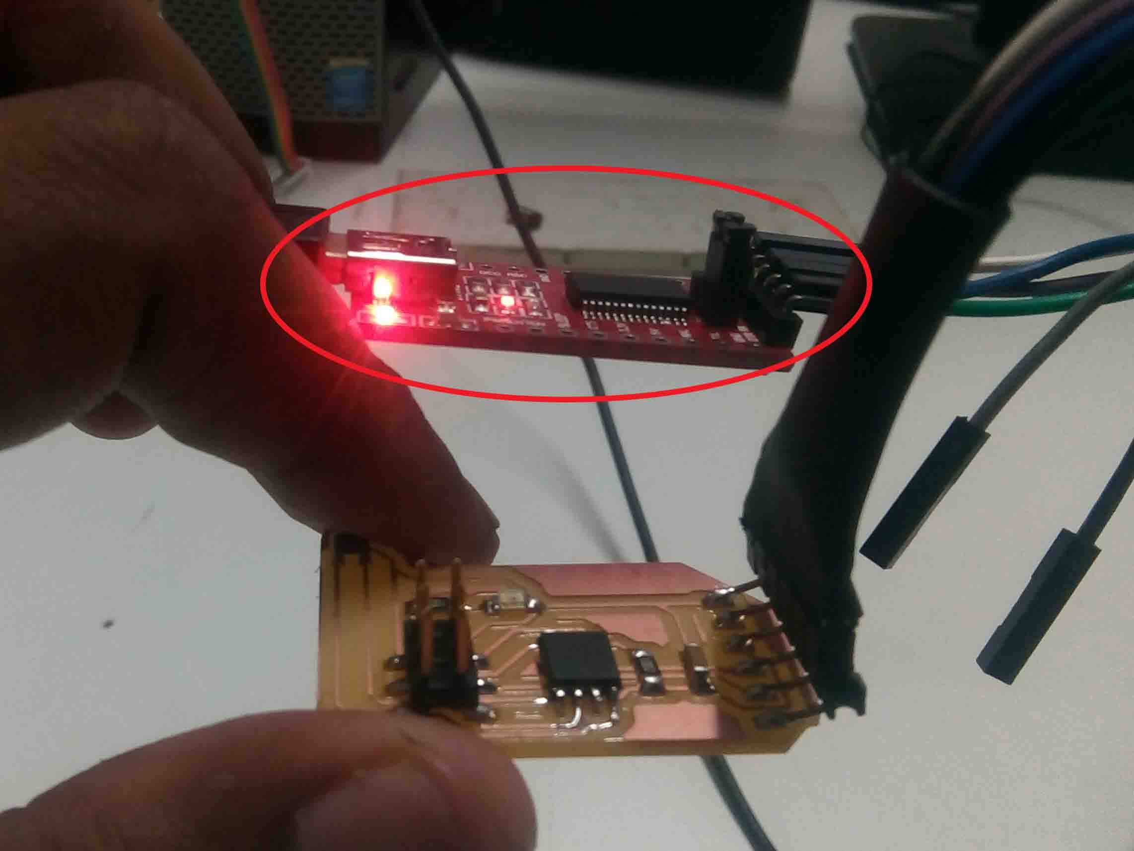
Now let's program the board and find the required values.
Programming
The programming part similar Week 9. The code is little bit different. Here we have to monitor the values from the "Hall Effect Sensor". In Arduino IDE there is a setup called "Srrial monitor". Through serial monitor we can see the values measured by the sensor. But first we need to program our board.
Enter the following code to IDE and upload...
#include <SoftwareSerial.h>
int sensorPin = 1;// hall effect sensor
int digitalValue = 0;// variable to store the value coming from sensor
int analogValue = 0;
SoftwareSerial Serial(3, 4);
void setup()
{
  pinMode(sensorPin,INPUT_PULLUP);

  Serial.begin(9600); // initialize serial communications at 9600 bps

}
void loop()
{
 digitalValue = digitalRead(sensorPin);
   analogValue= analogRead(sensorPin);
    Serial.print("Digital Value ");
  Serial.println(digitalValue); //print the value of sensor in digital
  delay(1000);
   Serial.print("Analog Value ");
  Serial.println(analogValue); //print the value of sensor in analog
  delay(1000);
}
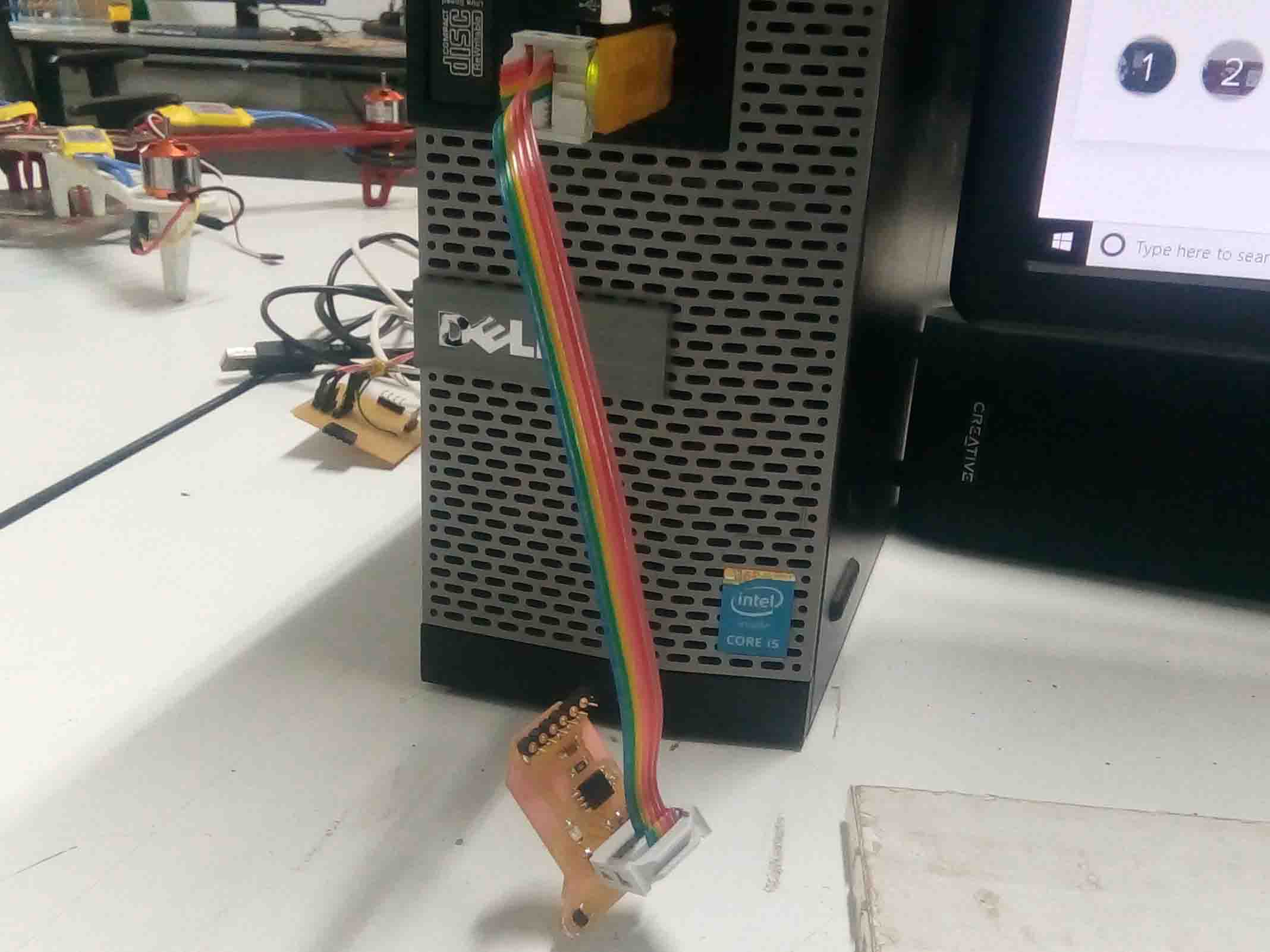
Now connect the board to an FTDI serial connector and coonect to the computer.
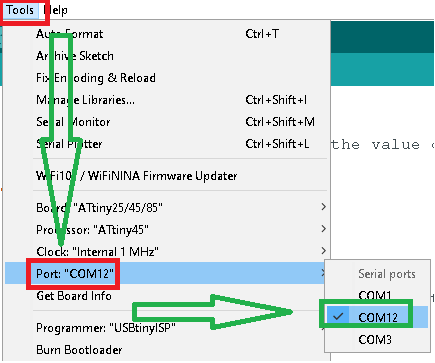
Now goto Arduino IDE, select "Ports" fromm tools. Make sure you select the right port with the serial connector. In my case it was "COM12".
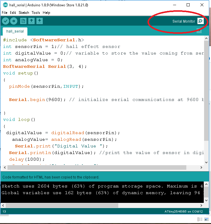
Now openthe serial monitor. It can be found top-right part of the Arduino tab.
Now brig a magnet close to the "Sensor"
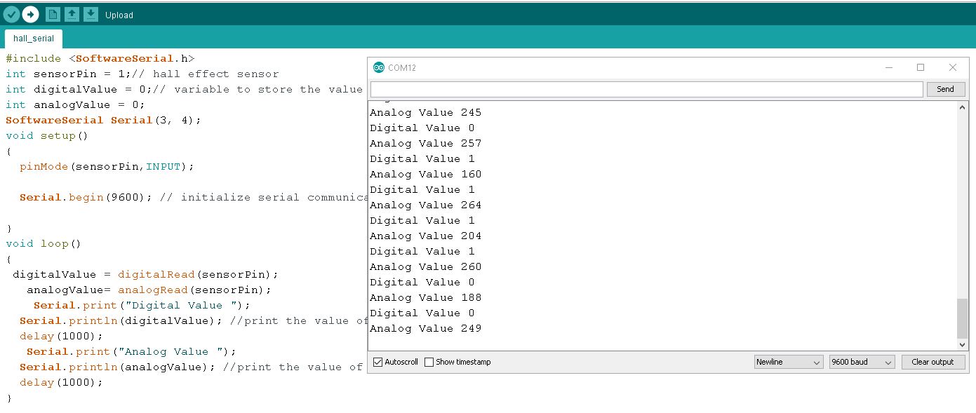
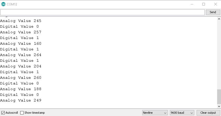
Now we can take the correct value for the magnetic sensor from the serial monitor
Now we need to re-program the board to work accordings to our findings.
Here is the program I gave after the measurement..
void setup()
 {
  pinMode(1, INPUT_PULLUP);
  pinMode(2, OUTPUT);
 }
void loop()
 {
    int data = digitalRead(1);
    if (data==LOW ) {
        digitalWrite(2, HIGH);
        }
    else{
         digitalWrite(2, LOW);
        }
 }
Upload the code into Attiny 45 and test it
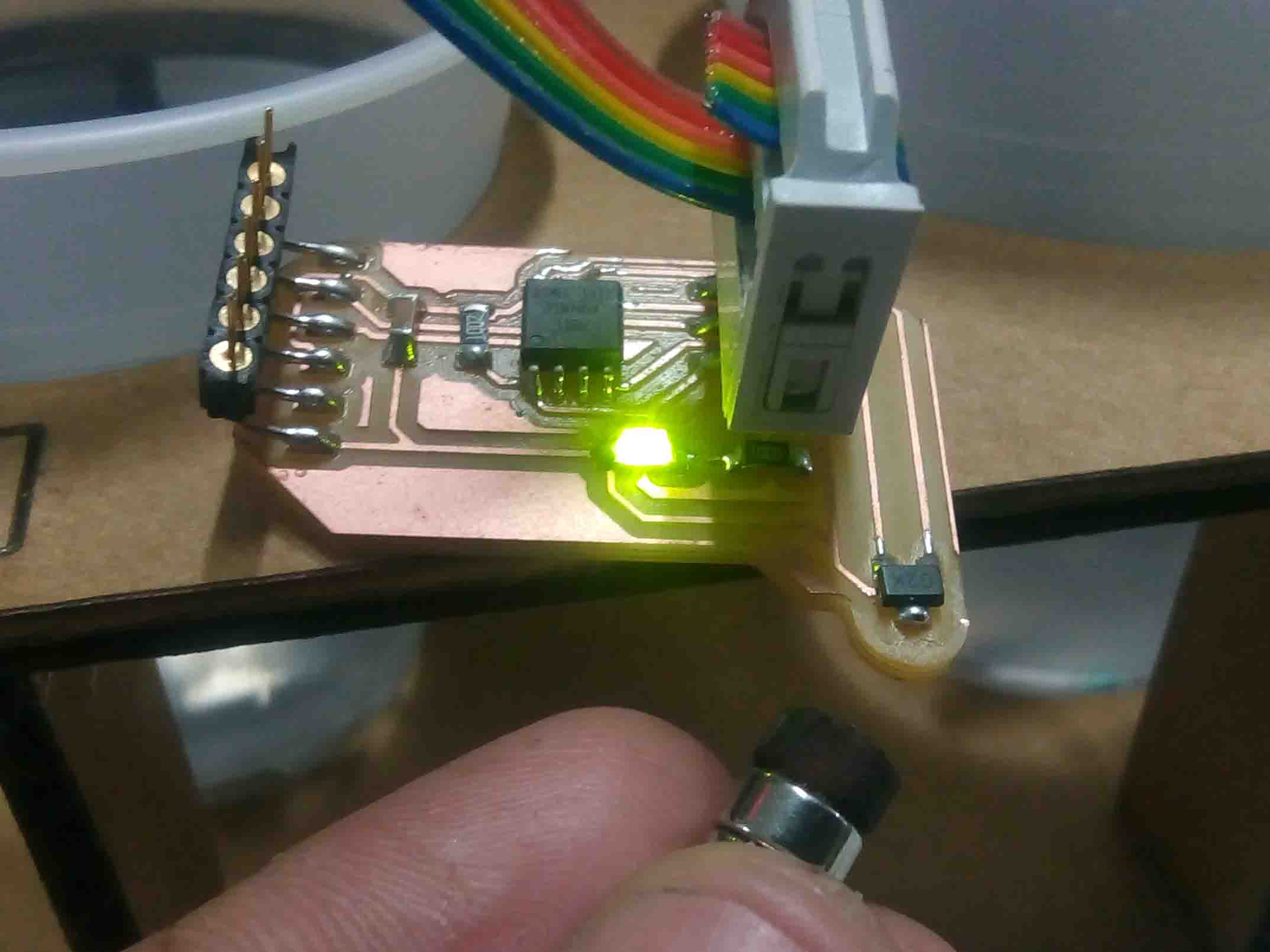
Here is a video for you..
So that's it for this week...
Group Assignment
So I measured the the analog and digital values of the "Hall Effect Sensor". For that I upload the following code to ATtiny 45...
           #include <SoftwareSerial.h>
           int sensorPin = 1;// hall effect sensor
           int digitalValue = 0;// variable to store the value coming from sensor
           int analogValue = 0;
           SoftwareSerial Serial(3, 4);
           void setup()
           {
            pinMode(sensorPin,INPUT_PULLUP);

            Serial.begin(9600); // initialize serial communications at 9600 bps

           }
           void loop()
           {
           digitalValue = digitalRead(sensorPin);
             analogValue= analogRead(sensorPin);
              Serial.print("Digital Value ");
            Serial.println(digitalValue); //print the value of sensor in digital
            delay(1000);
             Serial.print("Analog Value ");
            Serial.println(analogValue); //print the value of sensor in analog
            delay(1000);
           }
The analog signals are varying when the magnet is bring closer to the sensor. The values are given below
I also confirmed the working using a DSO.
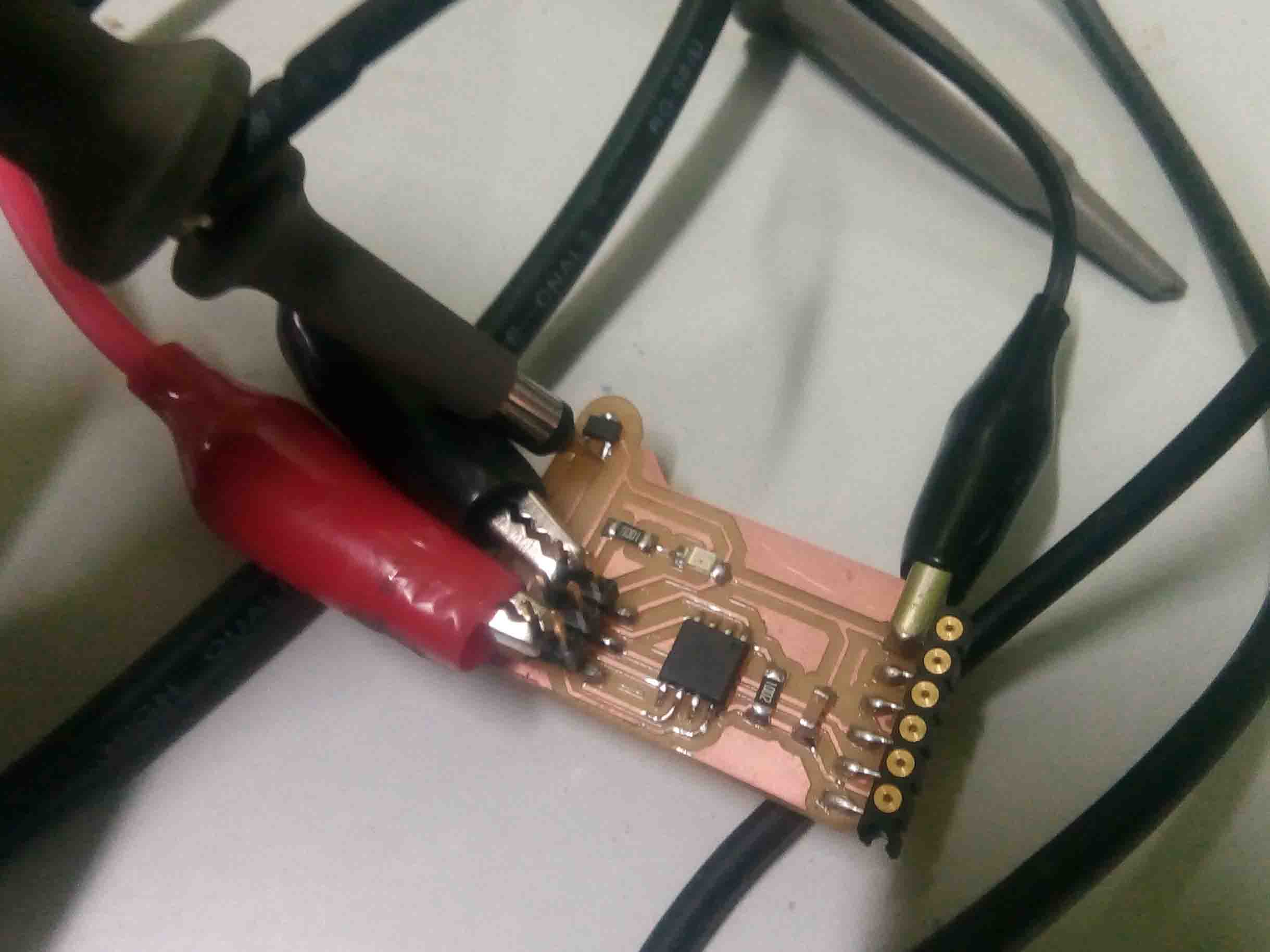
Here is the video..