Computer-controlled machining
Assignments
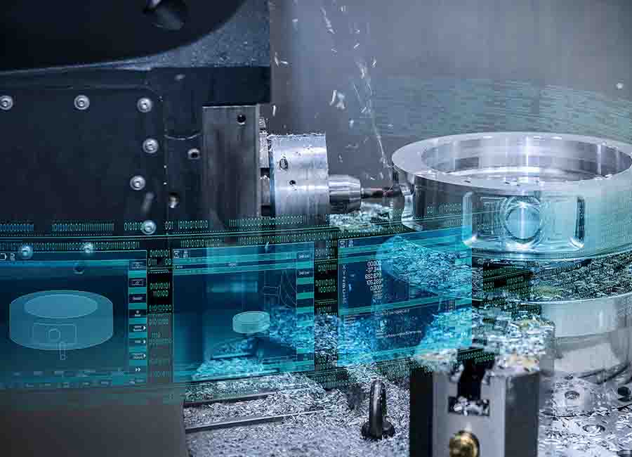
So this week we are leanrning about "Computer-controlled machining".Computerized Numerical Control(CNC) is a very helpfull tool in production of thing at large scale. It minimize human efforts in much effective way.
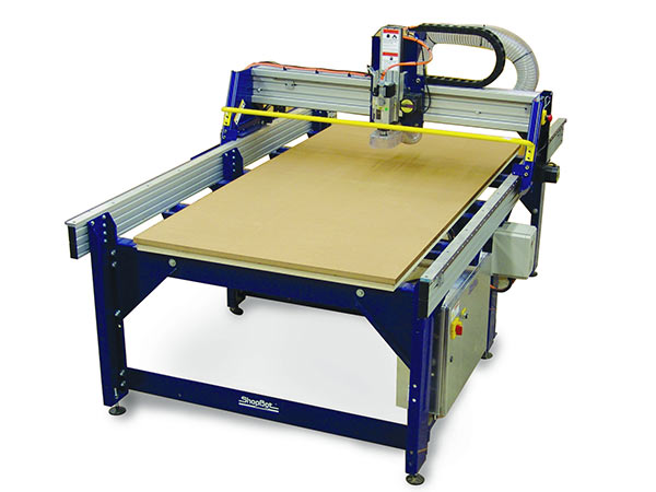
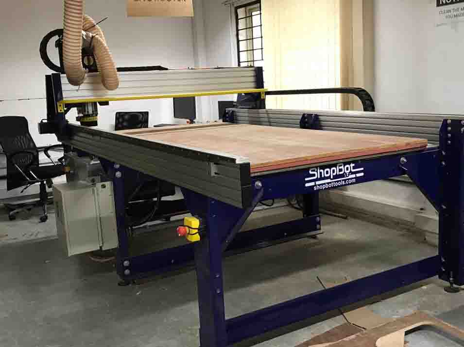
In our lab we are using "Shopbot" for this purpose. It allows to cut wood and other materials in a large scale. So let's meet shopbot...
Shopbot
A Shopbot is a computer-controlled cutting machine. A power tool router is affixed to the machine that directs its X and Y coordinates as it's cutting. ... CNC routers can be used to cut wood, foam, and plastics, but most hobbyists use it for carving wood.
Available in traditional shop-size and larger, all full size gantry tools are available with 8” or 14” Z travel. In addition to our standard size tools – 96 x 48, 96 x 60, 120 x 60, 144 x 60 – we can build your tool to any dimension up to 10’ by 30’ and with plunge depths up to 24 inches. Other customizable components are available, including dual Z options with two Z axes on the main gantry. You can download the details from Here
Shopbot consist of 3 Axis
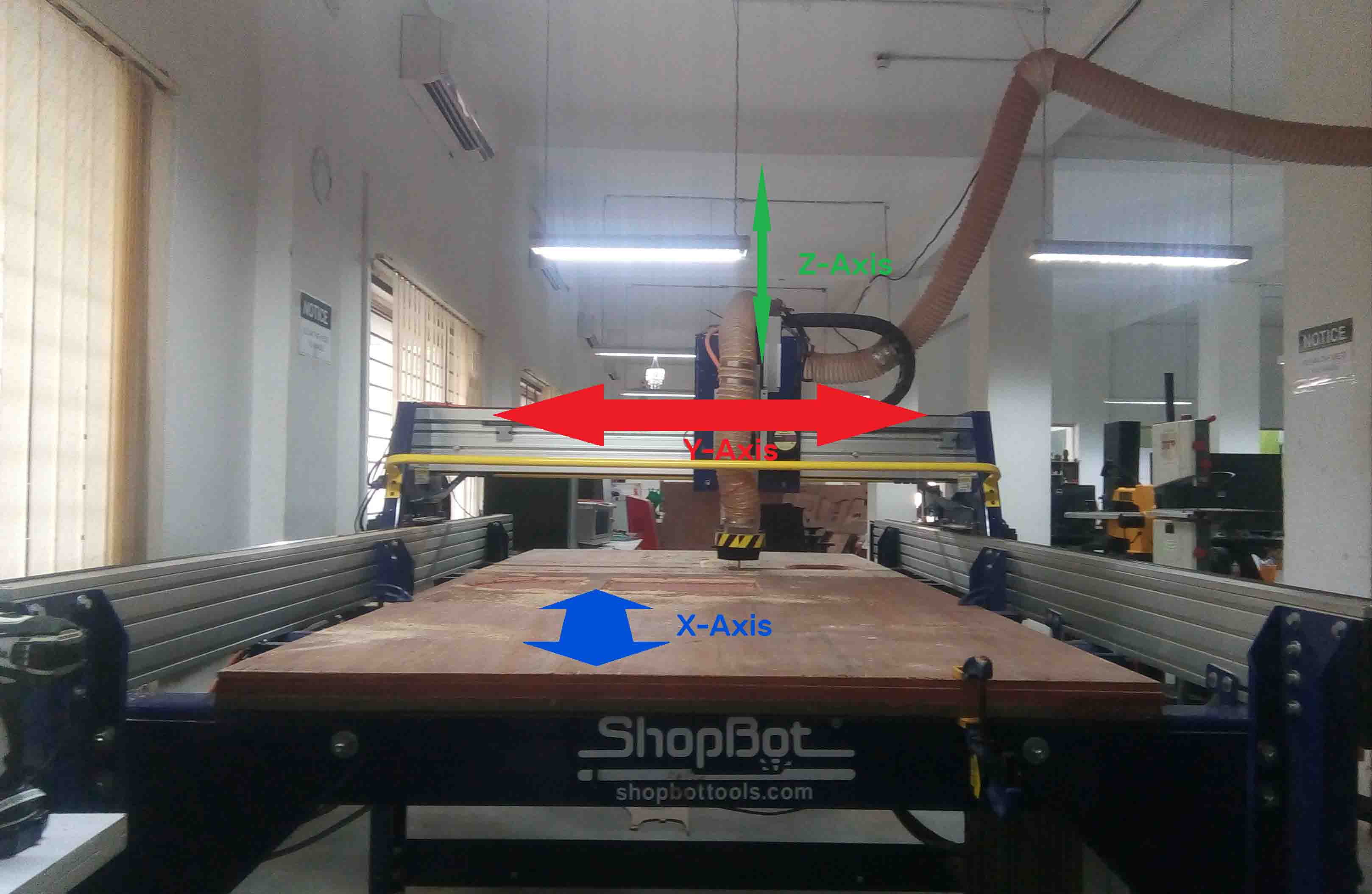
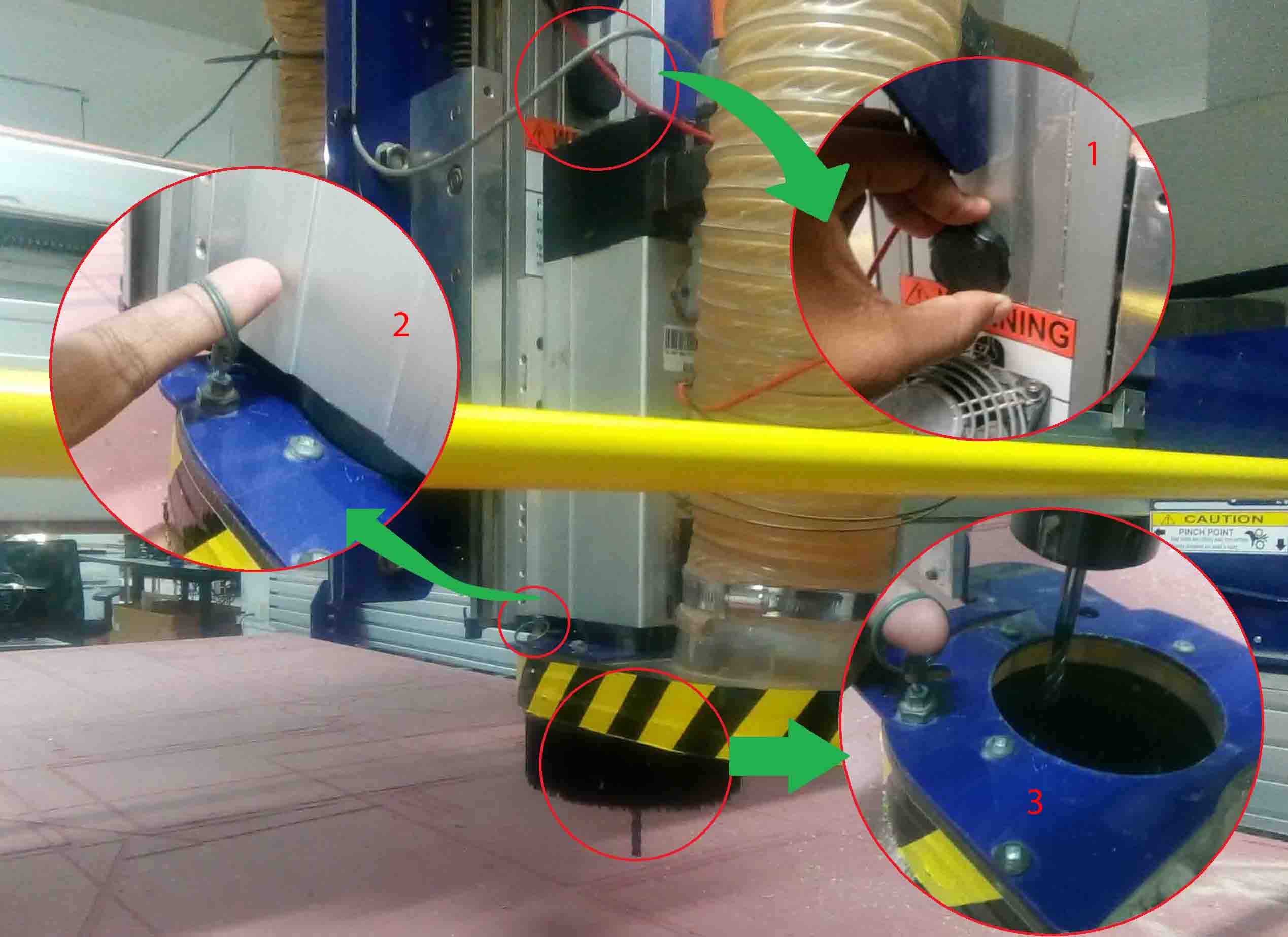
The X and Y axis are for Horizontalmovements. The vertical movement is covered by the Z-Axis. The Z-Axis contains "Spindle" and "Vaccum". Spindle contains the drill bit. Vaccum helps to clean the bed.
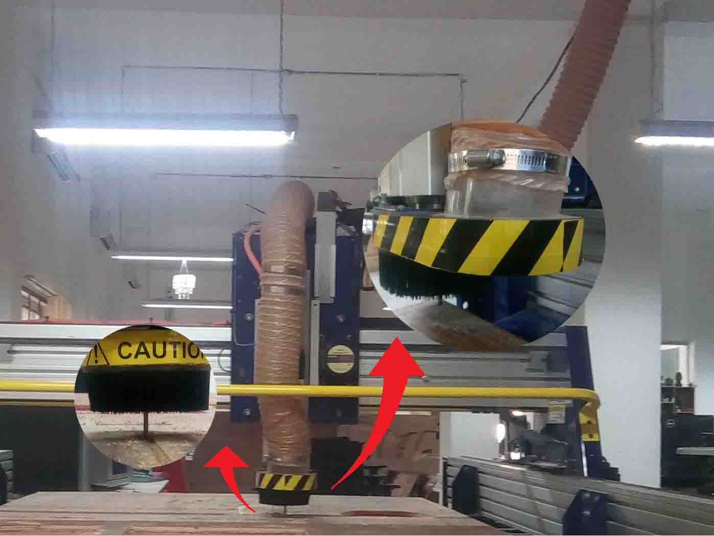
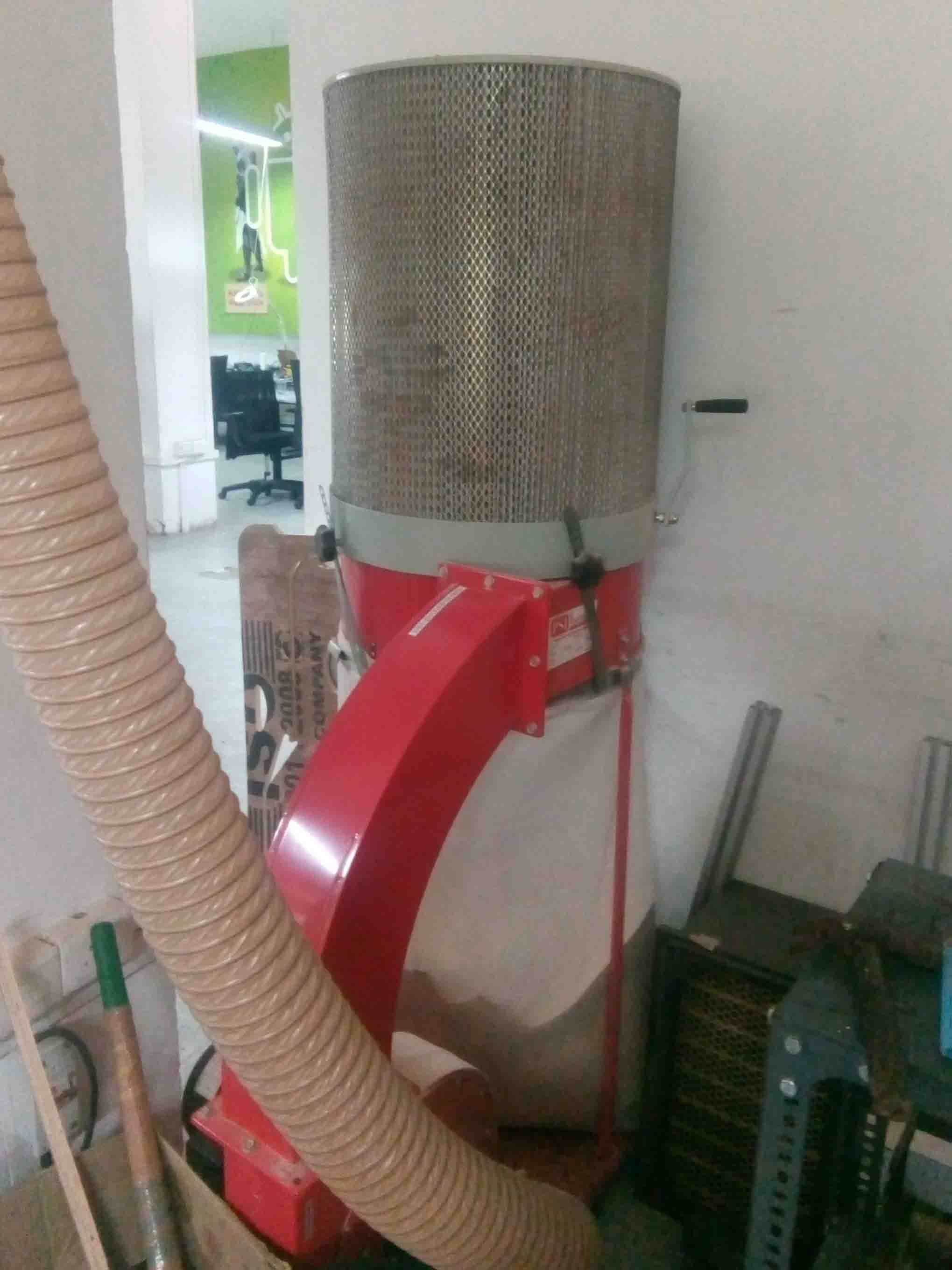
The end of the Vaccum is coonected to a suction vaccum cleaner which is given below
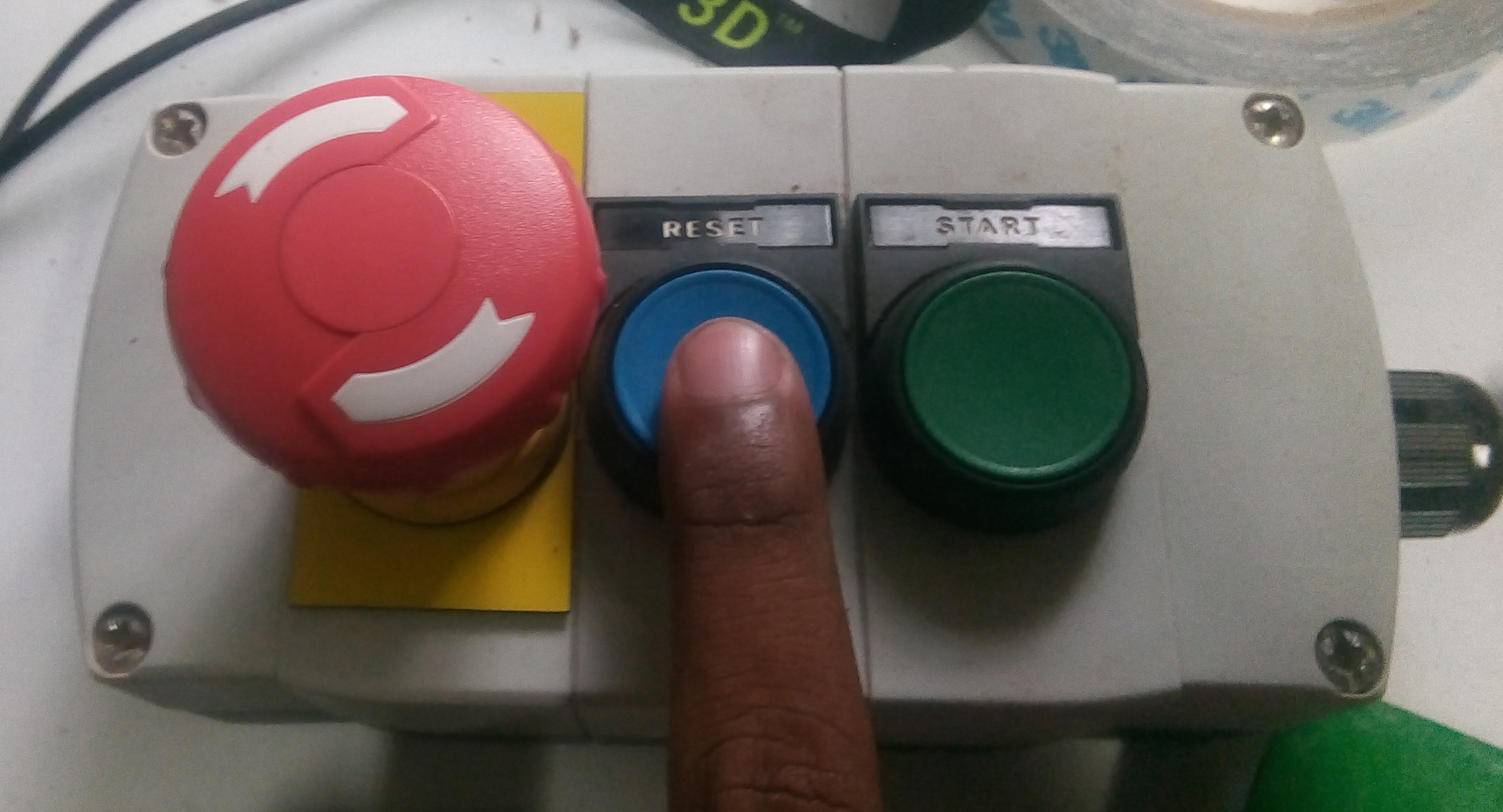
The shopbothave few safty mechanisms that is provided for the saftyof the users.
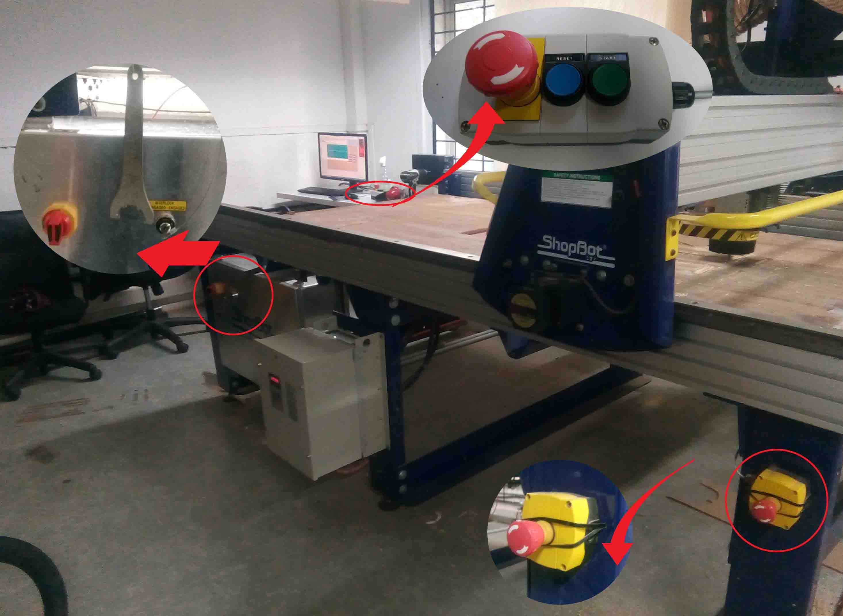
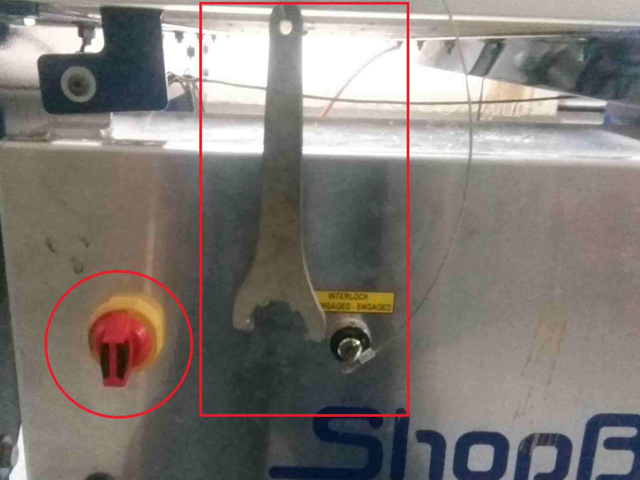
As you can see in the image, there are two emergency pause switches in case there is some problems occure. Also the "Power On/Off" knob is also given. There is a wrench given in order to change the bit from the spindle.
Before we get started we need to know bit about the drilling/milling bits...
Different Bits
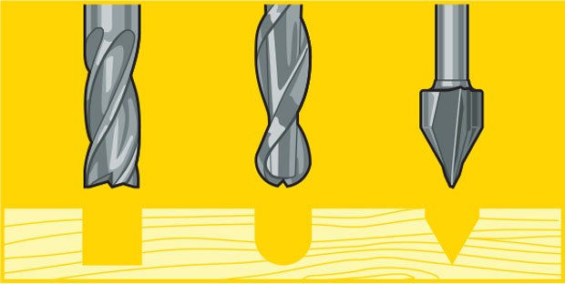
Drill Bits vs End Mills
CNC machining is a subtractive process that uses rotational cutting tools called “end mills” to remove material. An end mill, while similar in appearance to a drill bit, is far more versatile. However, in practice the terms “bit” and “end mill” are often used interchangeably.
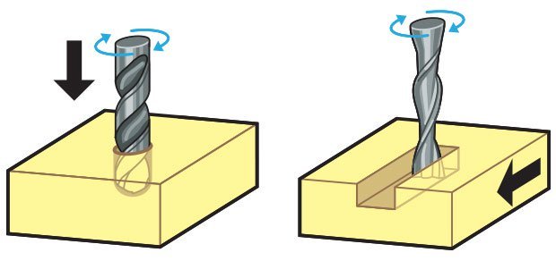
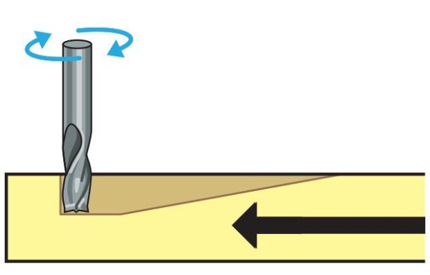
Here’s the key difference. Drill bits are designed to plunge directly into material, cutting axially and creating cylindrical holes. End mills are typically used for horizontal carving and cut laterally. Additionally, most mills are “center-cutting,” meaning they are able to cut both axially and laterally. This is due to cutting flutes that extend to — and protrude from — the end face and enable plunge cutting. To minimize tool breakage and stress on the material being cut, most CNC software will “ramp” the end mill slowly into lateral cuts.
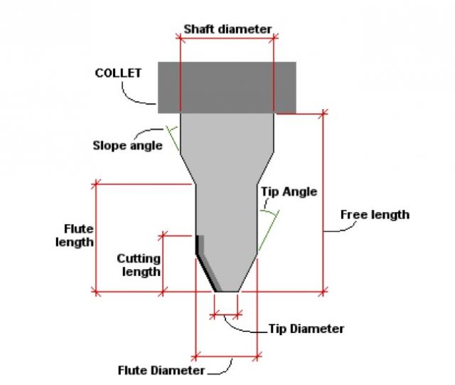
Tip Shapes and Applications
Choosing flat end mill vs. a ball end mill will determine the characteristics of the tooling marks (or lack thereof) on your model. Most jobs will benefit from strategic use of multiple size and shape tools for milling different features. End Mills are often used for roughing and 2D cutting and V-Bit and Ball Nose cutters are often used for finishing operations.
Up-cut, down-cut and compression cut determine the way the chips (cut material) are ejected and the smoothness of the surface. With an up-cut end mill, the chips will be ejected upward and the bottom of the material will be smooth. The down-cut end mill is the reverse by puching the chips downward and the top of the material is smooth. The compression end mill creates a smooth surface on top and bottom, which is perfect for pre-laminated woods.
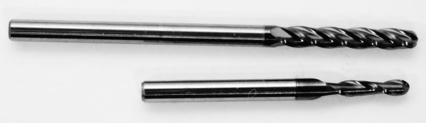
There are up-cut, down-cut, compression cut end mills with varying numbers of flutes. End mills are intended to cut horizontally.
Up-cut, down-cut and compression cut determine the way the chips (cut material) are ejected and the smoothness of the surface. With an up-cut end mill, the chips will be ejected upward and the bottom of the material will be smooth. The down-cut end mill is the reverse by puching the chips downward and the top of the material is smooth. The compression end mill creates a smooth surface on top and bottom, which is perfect for pre-laminated woods.
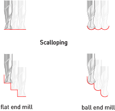
End mills come in a variety of shapes. The most common are flat end mills and ball end mills. Flat end mills will cut flat areas with no scallops. However, they leave a terrace-like scallop on non-flat surfaces. Ball end mills will leave smaller scallops for the same stepover value on sloped surfaces, but they will also leave scallops on flat areas. Flat end mills can be Center Cutting and Non Center Cutting: Center cutting square endmills are essential for plunge milling.
Each end mill tip shape is designed for a particular purpose. Some common cutter shapes are ballnose, fish tail, surface planing, v-carving, and straight.Ballnose mills produce a rounded pass and are ideal for 3D contour work, while fish tail cutters will produce a flat surface. V-bits produce a “V” shaped pass and are used for engraving, particularly for making signs.
The diagram above shows the difference in clearing path shape between a fish tail, ball nose and V tools. Ball nose mills are often selected when doing 3D contouring because their rounded edge reduces jagged steps when cutting several stepped layers. Ball nose mills can also be used to cut wide paths with rounded edges by reducing the step over amount (overlapping distance between) between passes. By overlapping steps, the central scallop shown in the diagram is eliminated.
Flutes and Chipload
Flutes are the helical grooves that wrap around the sides of the end mill. Each flute has a single tooth with a sharp cutting edge (although there can be more than one) that runs along the edge of the flute.
As the tooth cuts into the wood, each flute whisks away a small section or “chip”. The fewer the flutes, the more material that is ejected with each tool rotation. The overall cutting depth should never exceed the length of the flutes on an end mill. If cutting deeper than the length of the flutes, the tops of the flutes will be blocked and chips won’t clear, building up heat and reducing tool life
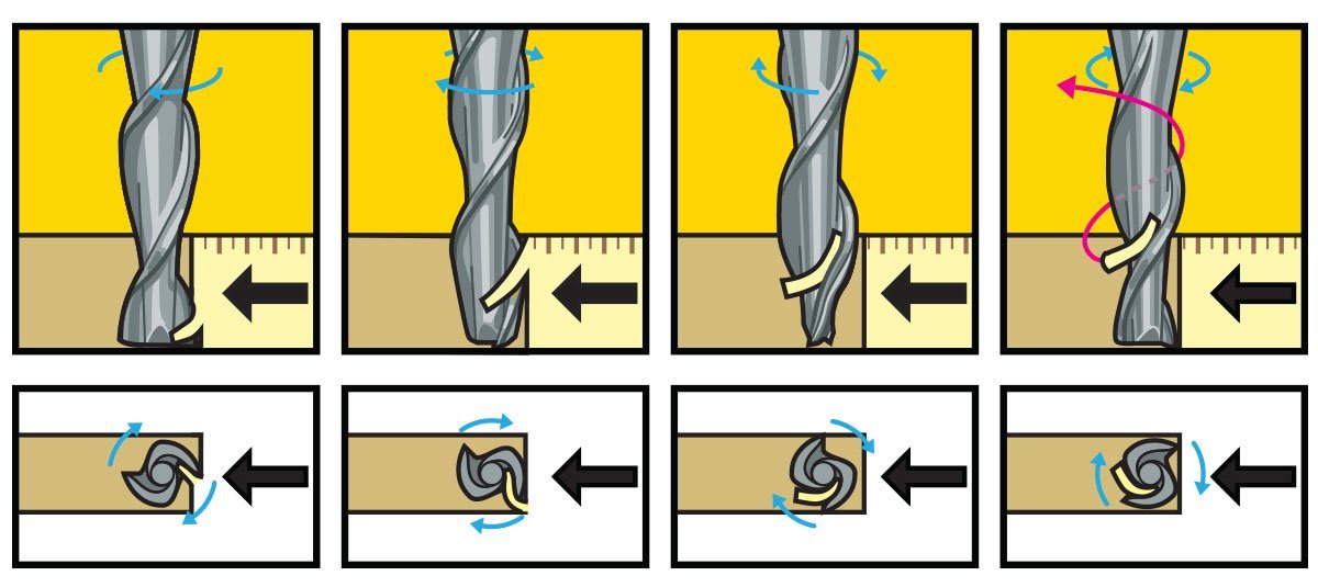
Chipload is the thickness of a machined chip as cut by a specific tool type. More flutes create a smoother surface finish, while fewer flutes remove material fastest, but make rougher cuts.Chipload is the thickness of a machined chip as cut by a specific tool type. More flutes create a smoother surface finish, while fewer flutes remove material fastest, but make rougher cuts.(Source:https://makezine.com/2014/09/10/endmills/, https://wiki.imal.org/howto/cnc-milling-introduction-cutting-tools)
Group Assignment
Test runout, alignment, speeds, feeds, and toolpaths
So for testing some parameters in shopbot, we have designed a structure in Solidworks.
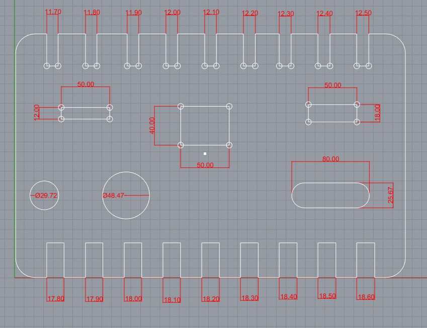
This was our Group Assignment.
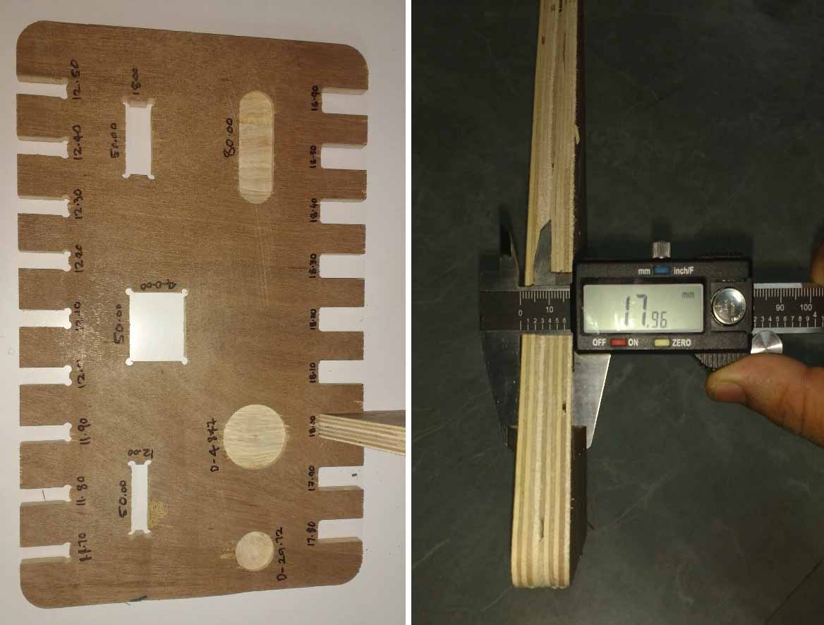
This was our group assignment to find the press fit dimension for the 12mm and 18 mm plywood .So we cut slots from 18.90 to 17.80 in steps of 0.1mm and for 12mm from 11.70 to 12.50 in steeps of 0.1 mm.
We found out that the right fits comes somewhere near 18 mm and 11.7 mm. The material thickness does vary a bit with temperature ,moisture etc.
Make Something Big
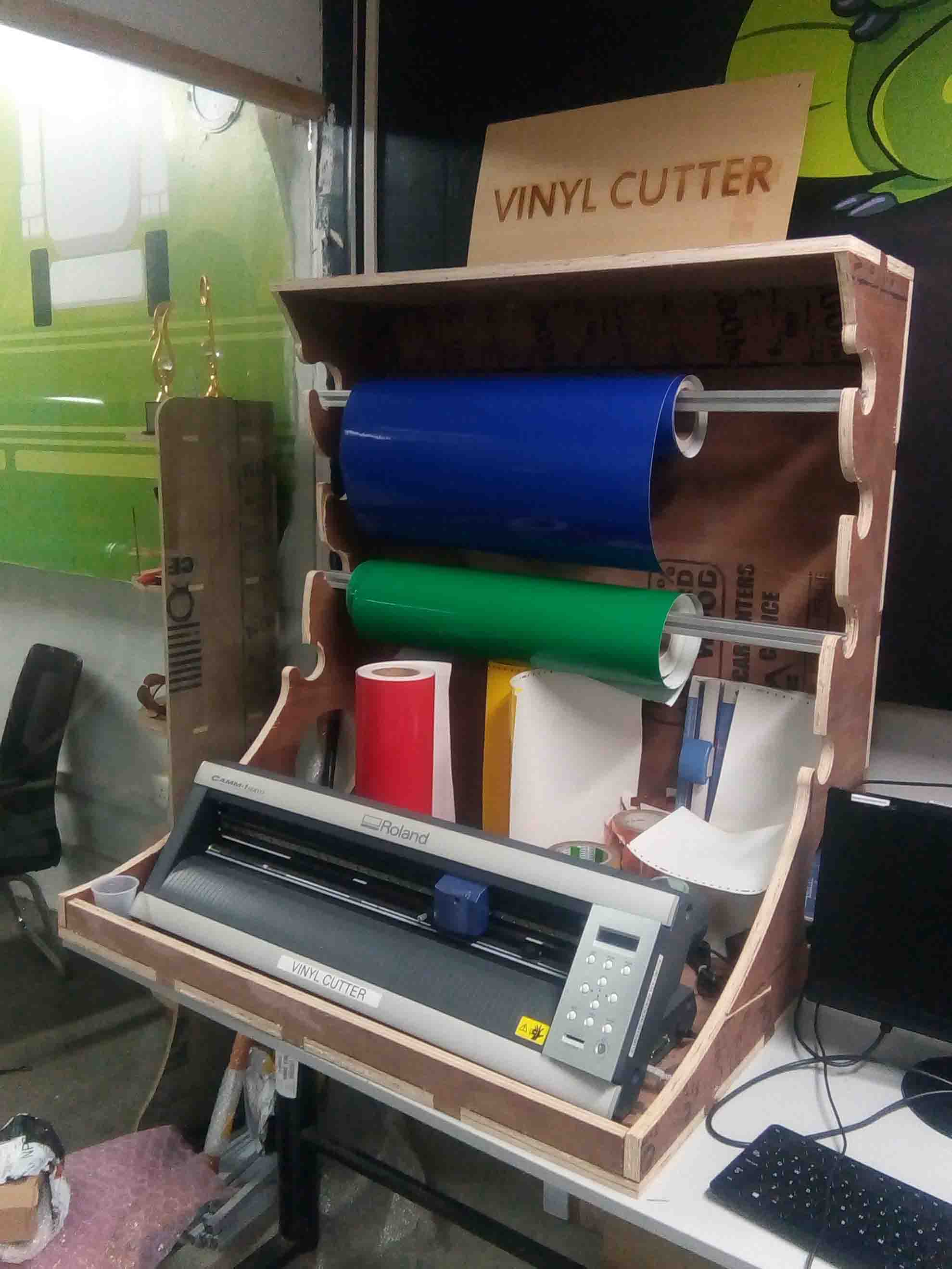
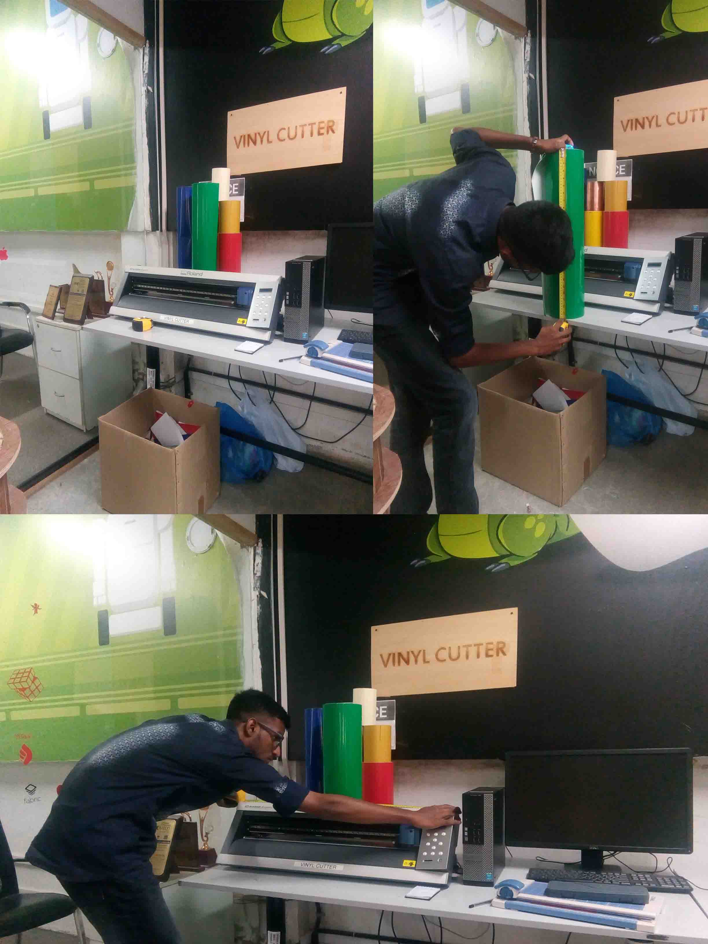
So after learning about cnc, I have decided to make a Cover+Vinyl holder for the vinylcutter in our lab. For that, I take the measurement of the available materials and equipments related to vinylcutter. I use a tape for that..
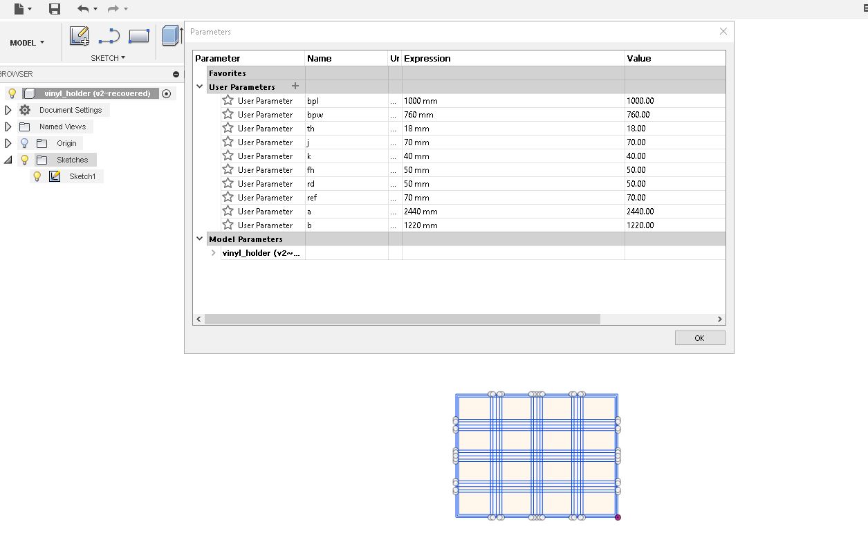
I listed out all the data I wanted and Uploaded into Fusion 360. I done some parametric designs in the last weeks. So I follow the same method for designing the cover. For that I started from the base layer. I add the data that I collected to "Parameters".
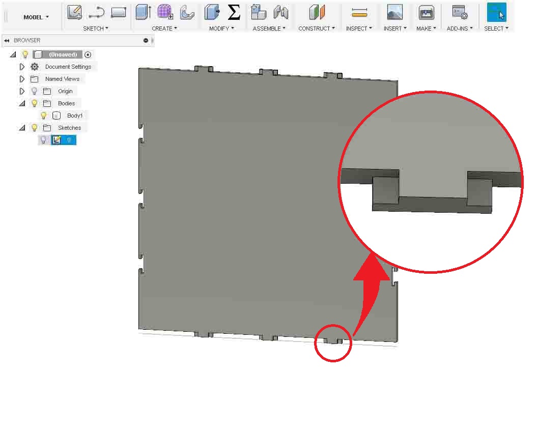
I designed a "T-Slot" joint so that I can fit the parts without any screws. I extruded the base to the thickness of 18mm. Becausr it was the thickness of the wood that I was going to use.
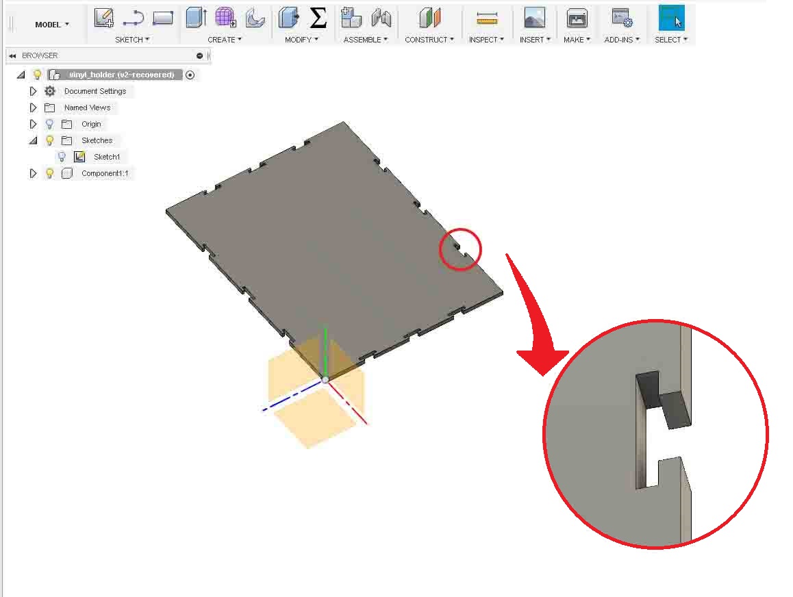
As you can see in the above image, the lock has formed on the edges of the base. Now we need to make a back. So it need to be designed to fit in the slot and it should accomadate the side pieces.
There is a male joint is given to fit in the female joint of baseplate I designed above. Now I need to make the rest of the parts. So let's continue with the most complicated part. The side part. The side part should hold the vinyl rolls. Also it should rotate freely. So I designed it to accumalate four rolls of vinyls.
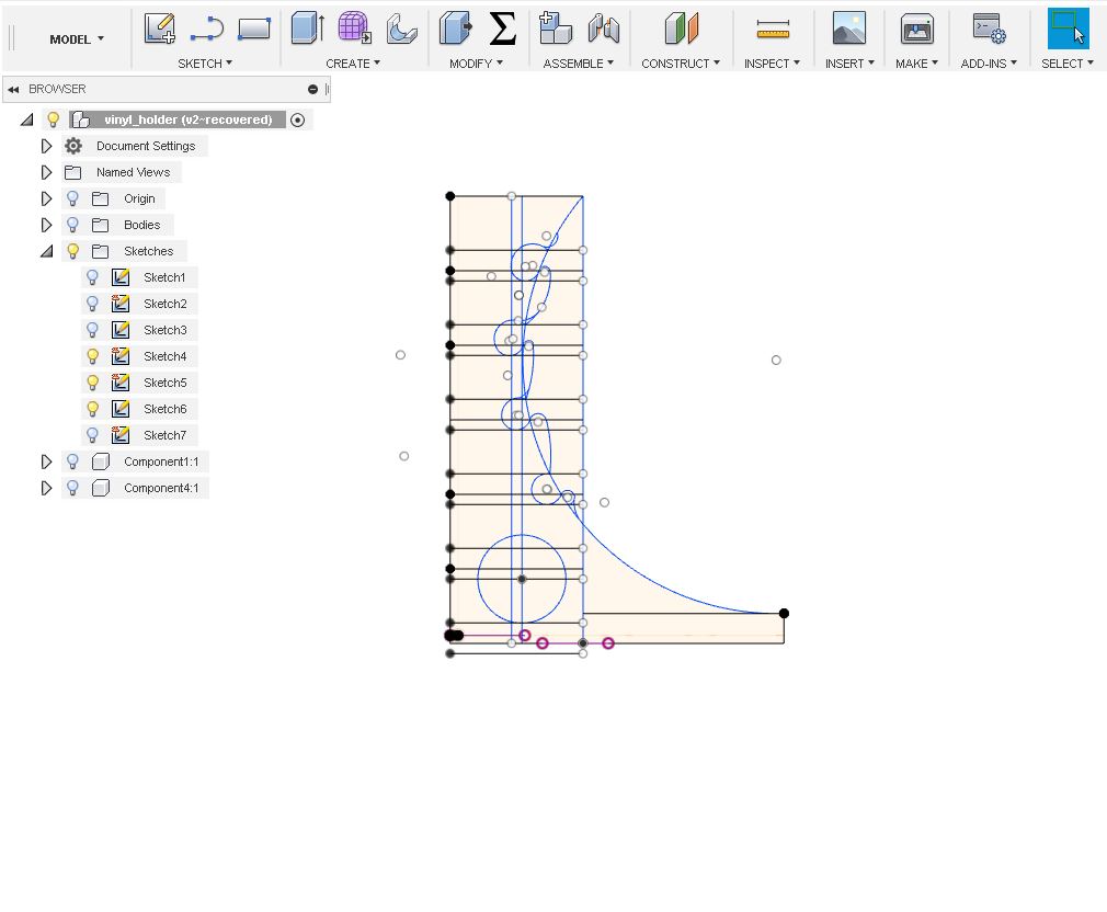
This is the basic sketch I made in fusion 360 before I extrude.
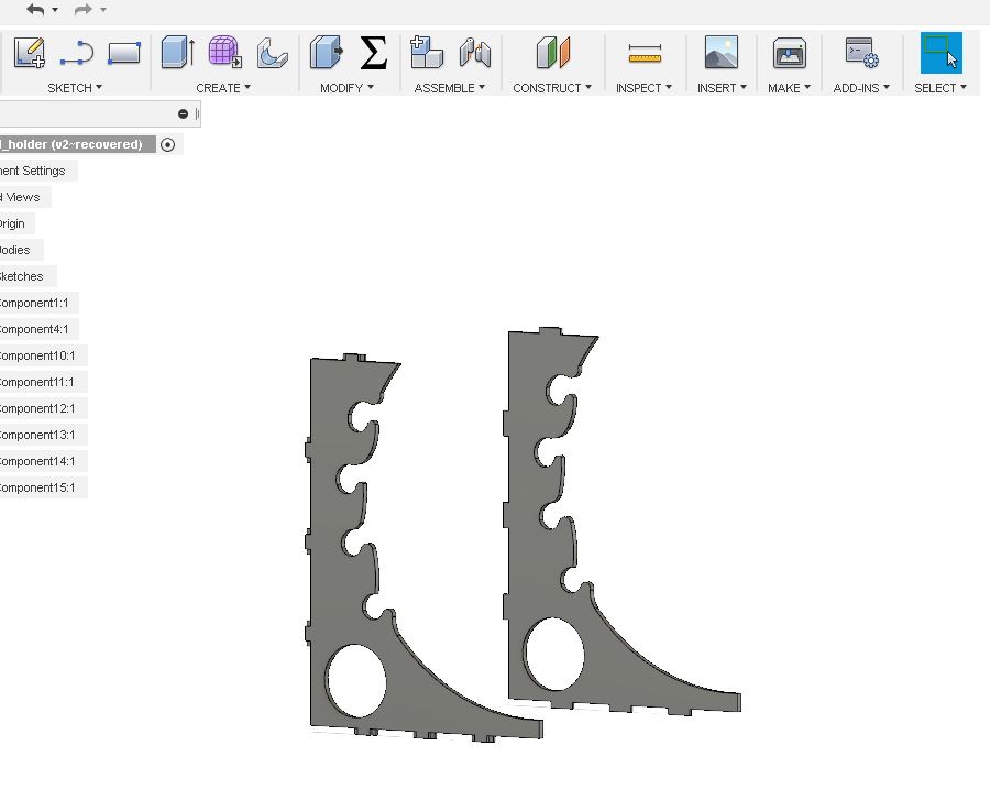
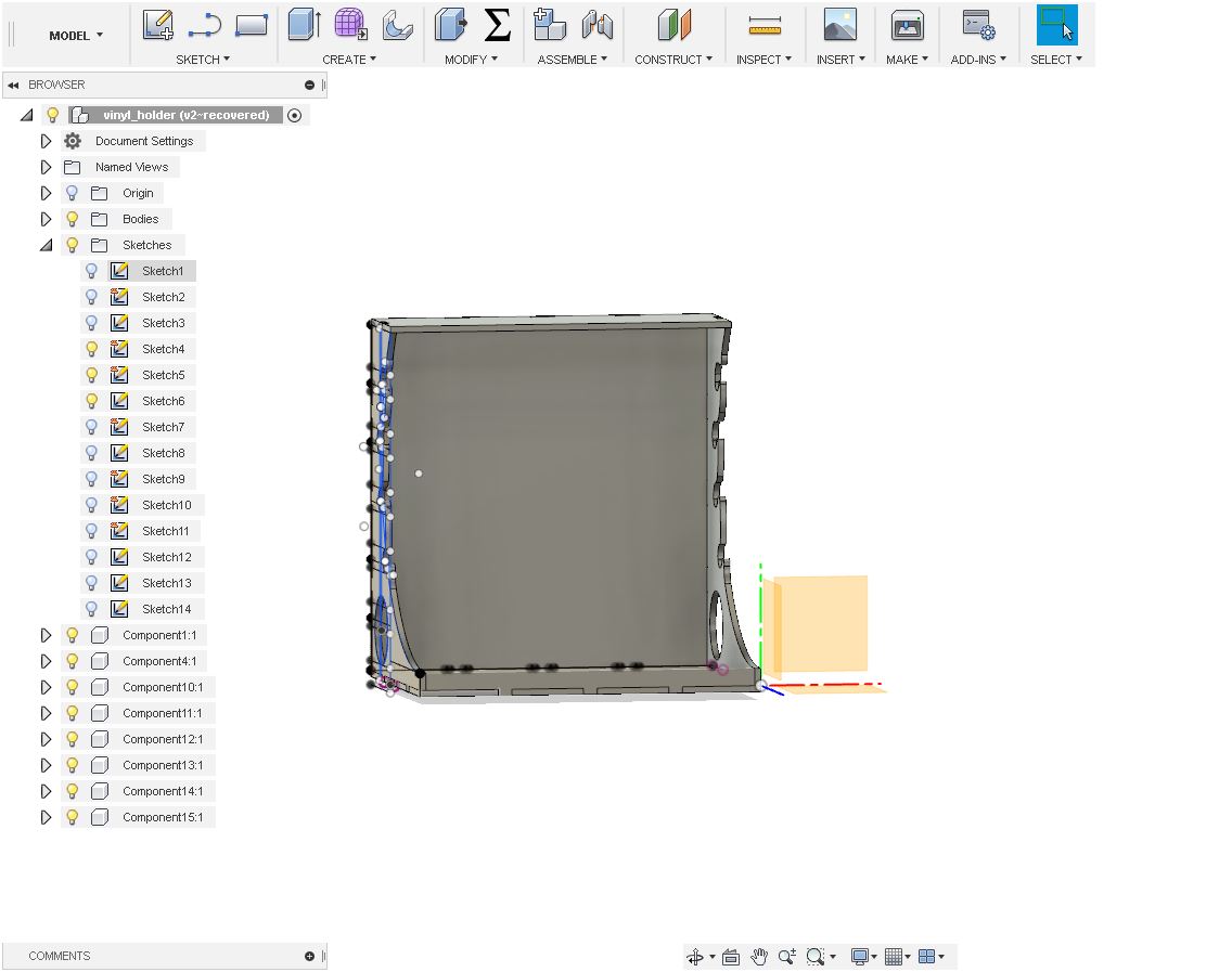
I extrudes in the thickness of 18mm. I need two side parts. So I mirrored the first piece to make an other one. Now I need to make the rest of the parts.A front plate and a top plate. Afer making that, the whole structure look like this.
I made each part as components. before cutting the parts, I needed to add the "Dogbone Fillet". Its an additional plugin need to be added to the Fusion360. You can download the files Here
Now go to "ADD-INNS". There you will get the following box
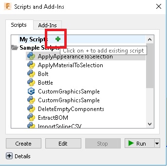
Now click the "+" under "My Script. Now select the file we download from above and open it
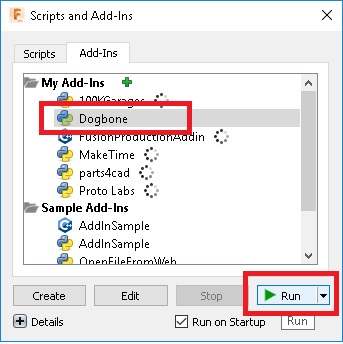
Now select "Dogbone" under "Add-inns" and click run. Now we have to add Dogbone to the joints for that select a component and add Dogbone
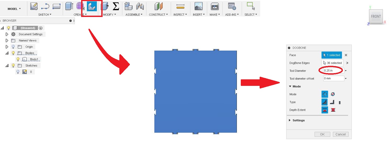
First click "Dogbone". Then select the compnent. Add the tool diameter and click "OK"
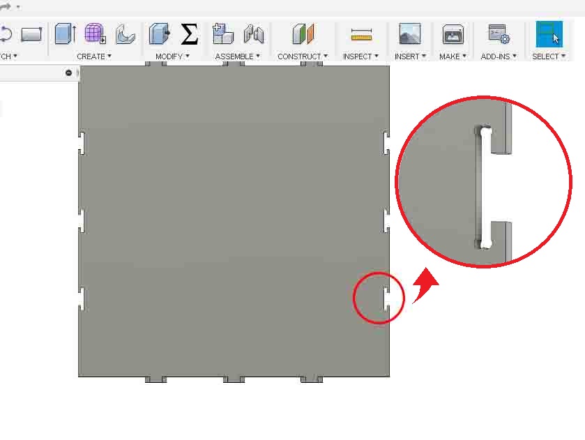
I repeat this process and give Dogbone to all joints. After that I export the files as DXF. You can download the files from Here
Preparing the Jobs
So we have designed case for vinylcutter holder. Now we have to make G-Code that understandable to Shopbot. For that I opened "V-Carve on the system linked to shopbot."
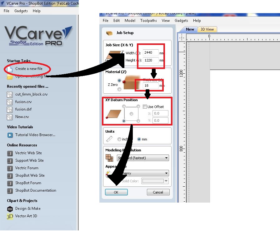
Now click "Create new file" and fill following:
Now set origin point and click "Ok"
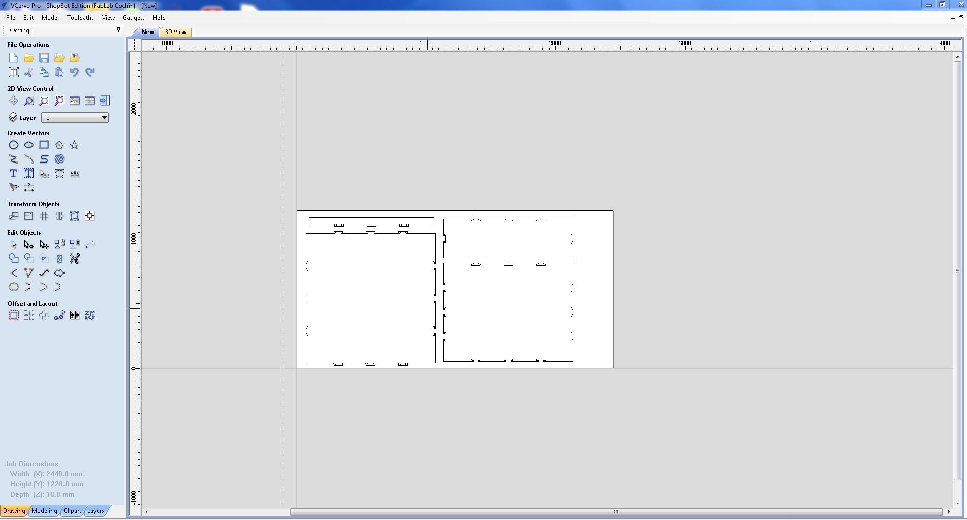
Now we have to open a the files. For that open .dxf file that we expoted from Fusion360 to V-Carve.
Now we need to to add some drill holes fot fixing the wood to the bed. For that, I selected a "circle tool" and draw few circles away from cut pieces. Always remember to set offset distance of the drill bits diameter between work piece and holes.
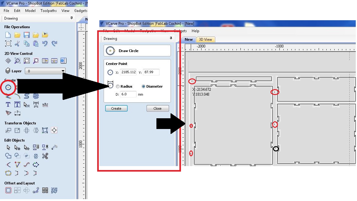
Here I have set a radious of "6.0mm" to the holes and set depth as "2.0mm". Next we need to create tool paths for each operations. For that select tool path from top right corner of the window. Click "Drillling Toolpath".
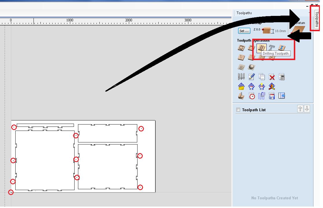
Now select each holes and group them. Set cut depth 2.0 and click "Select". We have to select the right tool for this operation. I am using and end mill with diameter of "1/4 inch".Select the end mill and click "Ok".
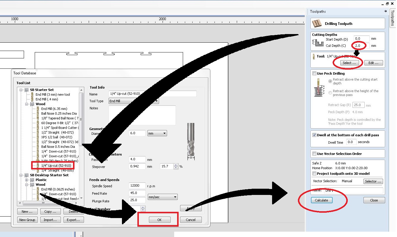
Now click "Calculate" to view the 3D pathway.
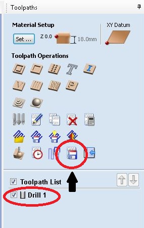
Now close it and it will take you to the main window. Now select drill 1 and click "Save" icon. It will save to required folder.
For "T-slot joints, We need to cut "Pokets" in the work piece, For that selects "Pocket Tool path". Correct cut depth as 9.0 mm and click edit passes.
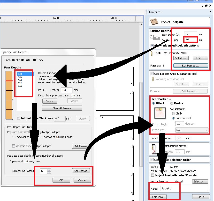
Now set the passes as "5". and click "Ok". Also select clear pocket as "Conventional" and claculate. Repeate saving and viewing to ensure the completion of work.
Now we need to cut the profile. For that click "Profile cut" from toolpath tab
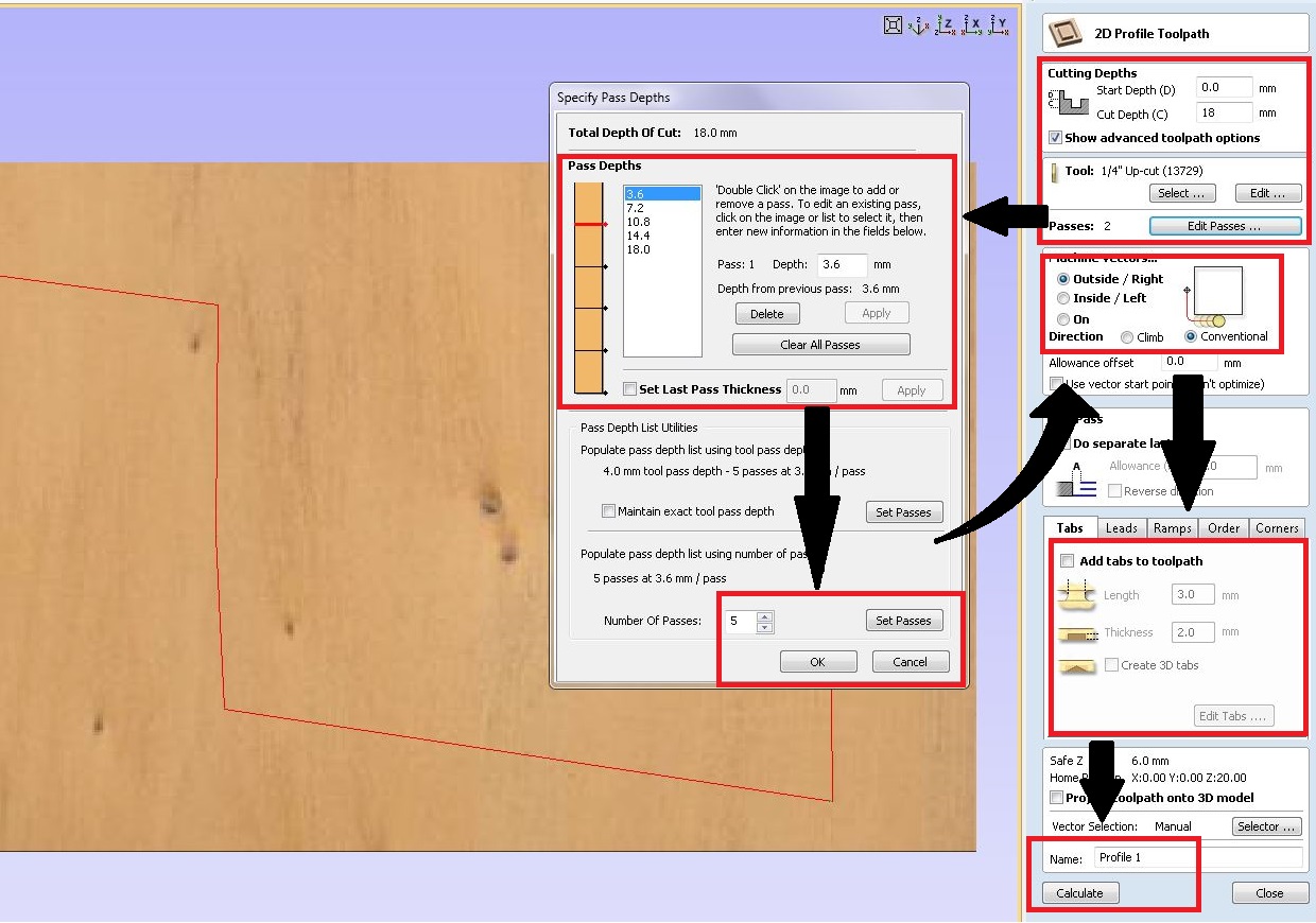
Set the following Parameters
Now click "Ok". Now select "Macchine vectors" as "Outside". and add tab of following parameters:
Now give a name and save as we did in the Previous work.This work piece is filled using current cut. So we had to take an another wood piece to cut the side pieces of the vinyl holder.
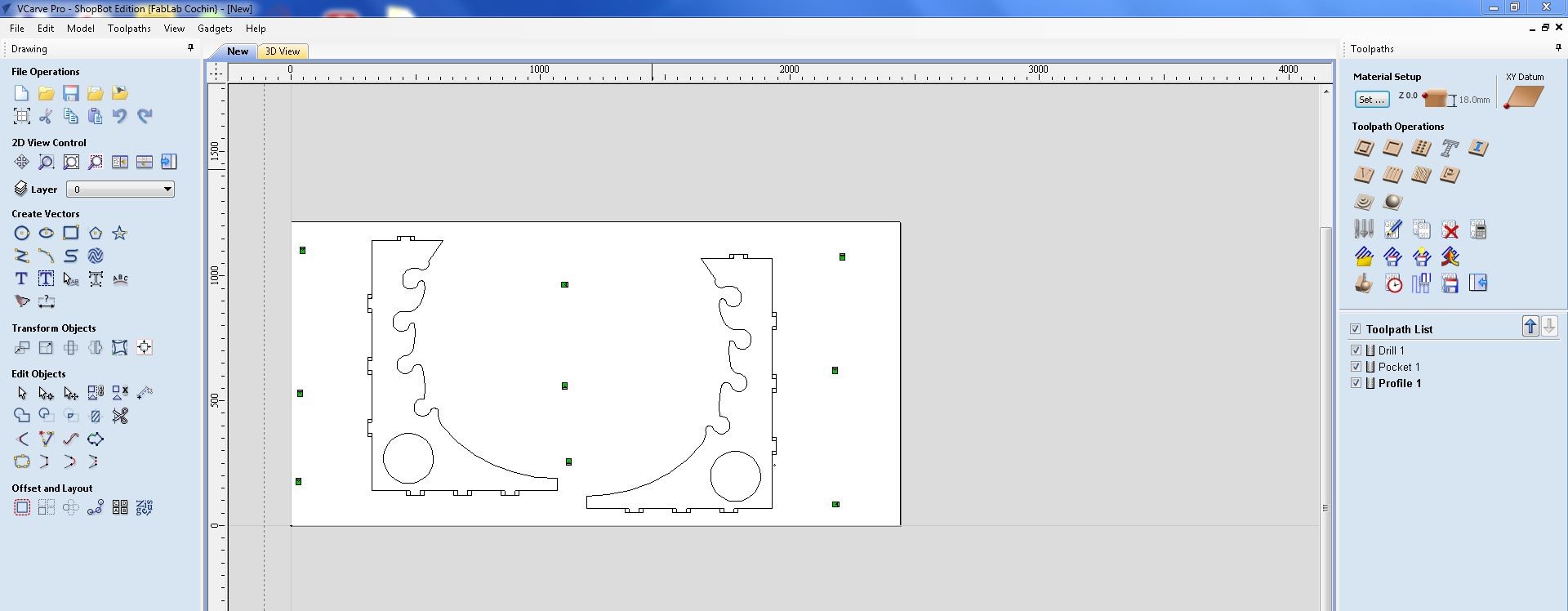
Add profile cuts and pockets. Save their worksheets in the desired folder.
Preparing Work Piece
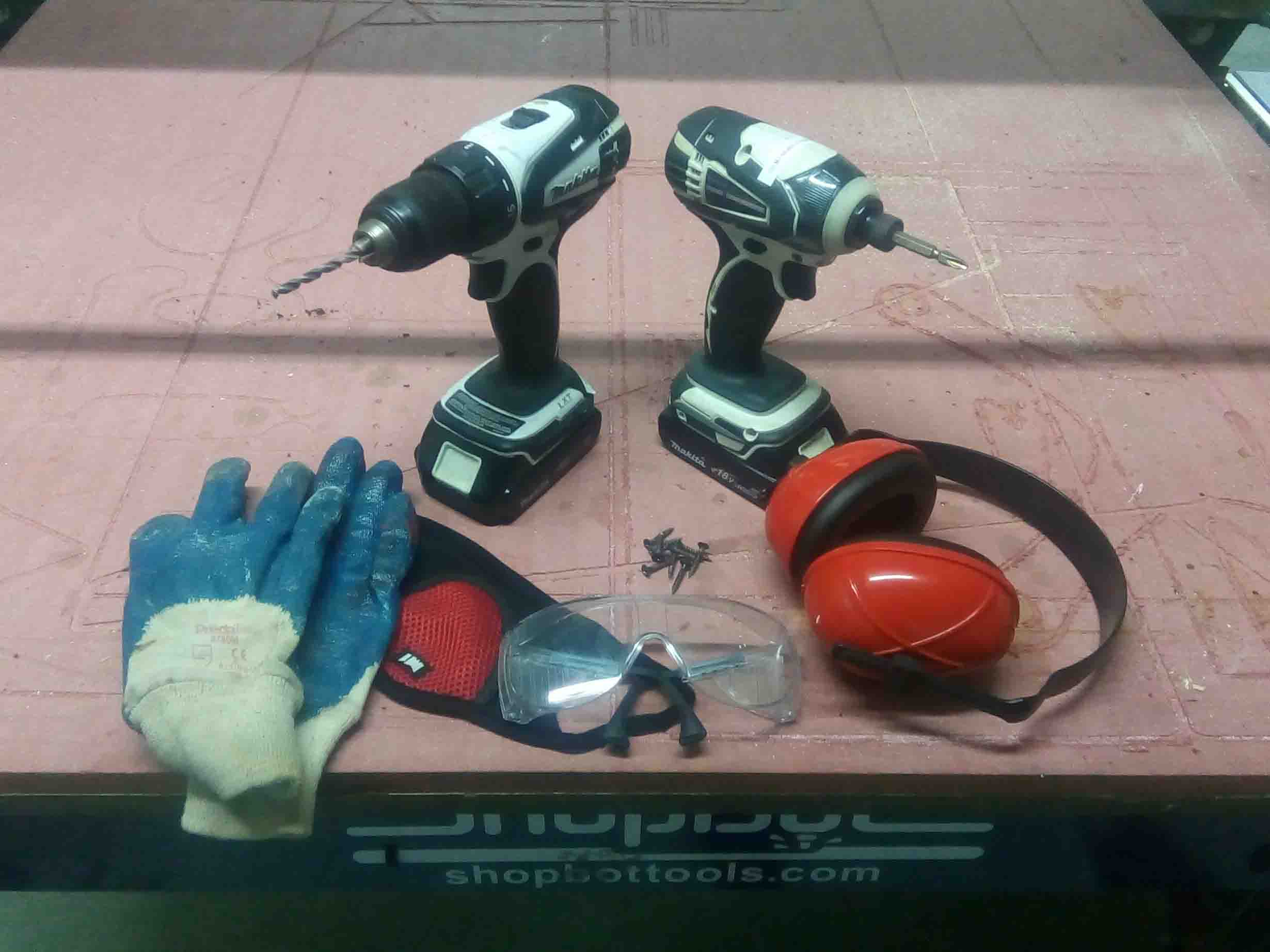
Before we begin, wee need to take some safty precausions. Also we need some tools. Here is a list of tools and safty we equipments we need:
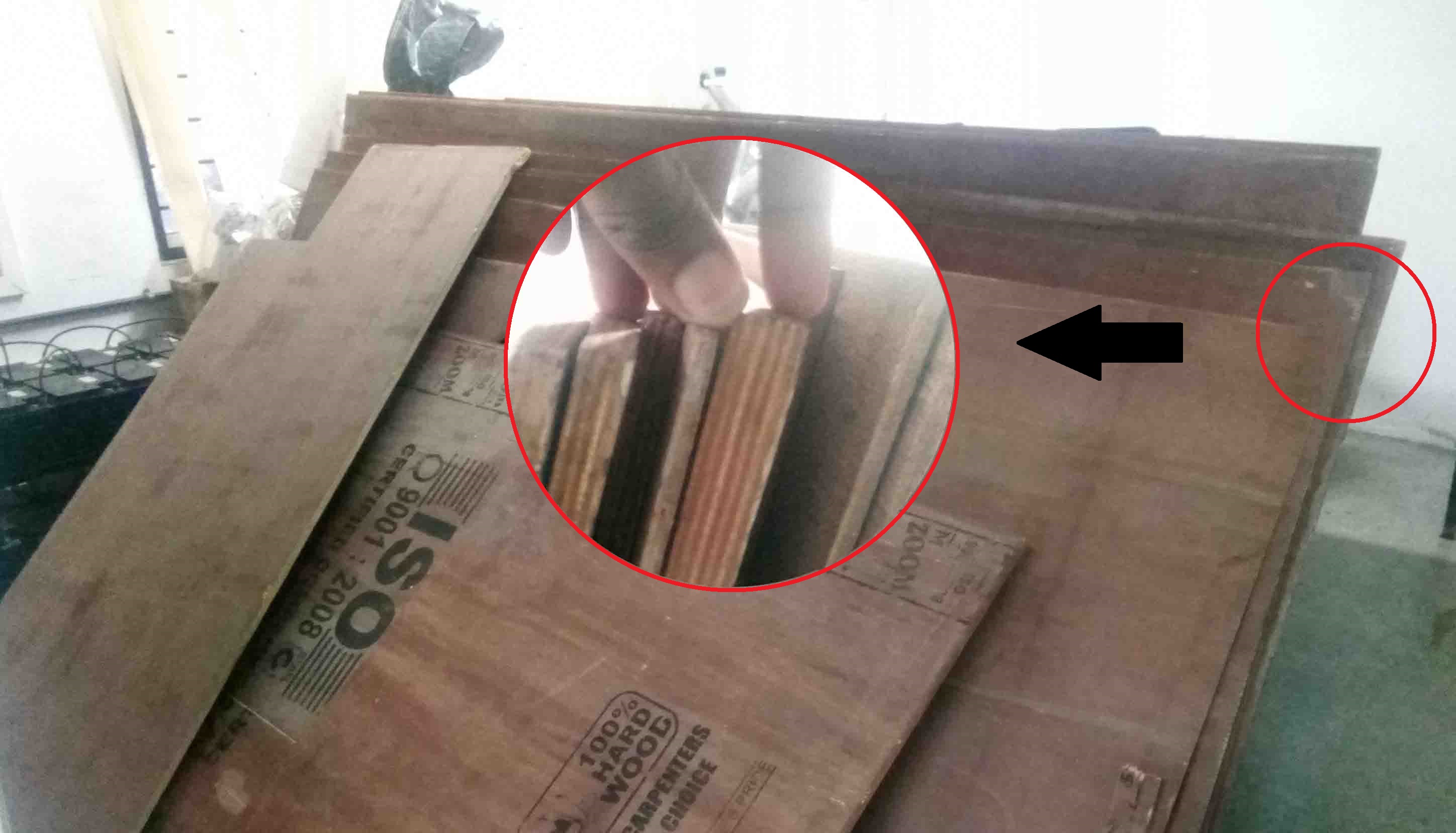
Now we need to select the wood. I take a 18mm wood..
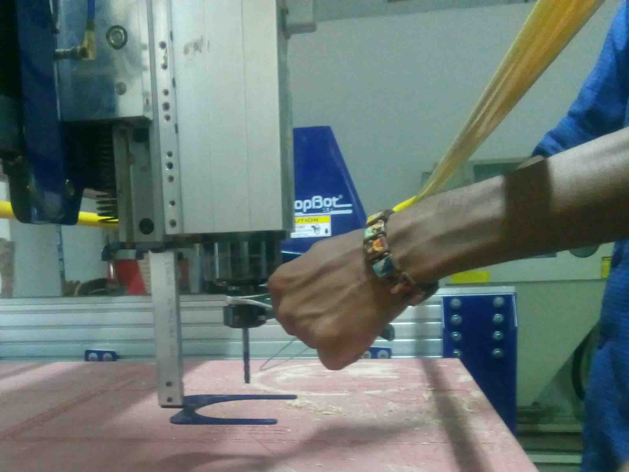
Now we have to place the wood on top of the bed. Before that we need to change the drill bit.For that follow these instructions.
Now we need to change the the bit from the chuck. For that we need to unscrew the bit. For doing that I have taken a spanner and the special tool that attached to the spindle key.
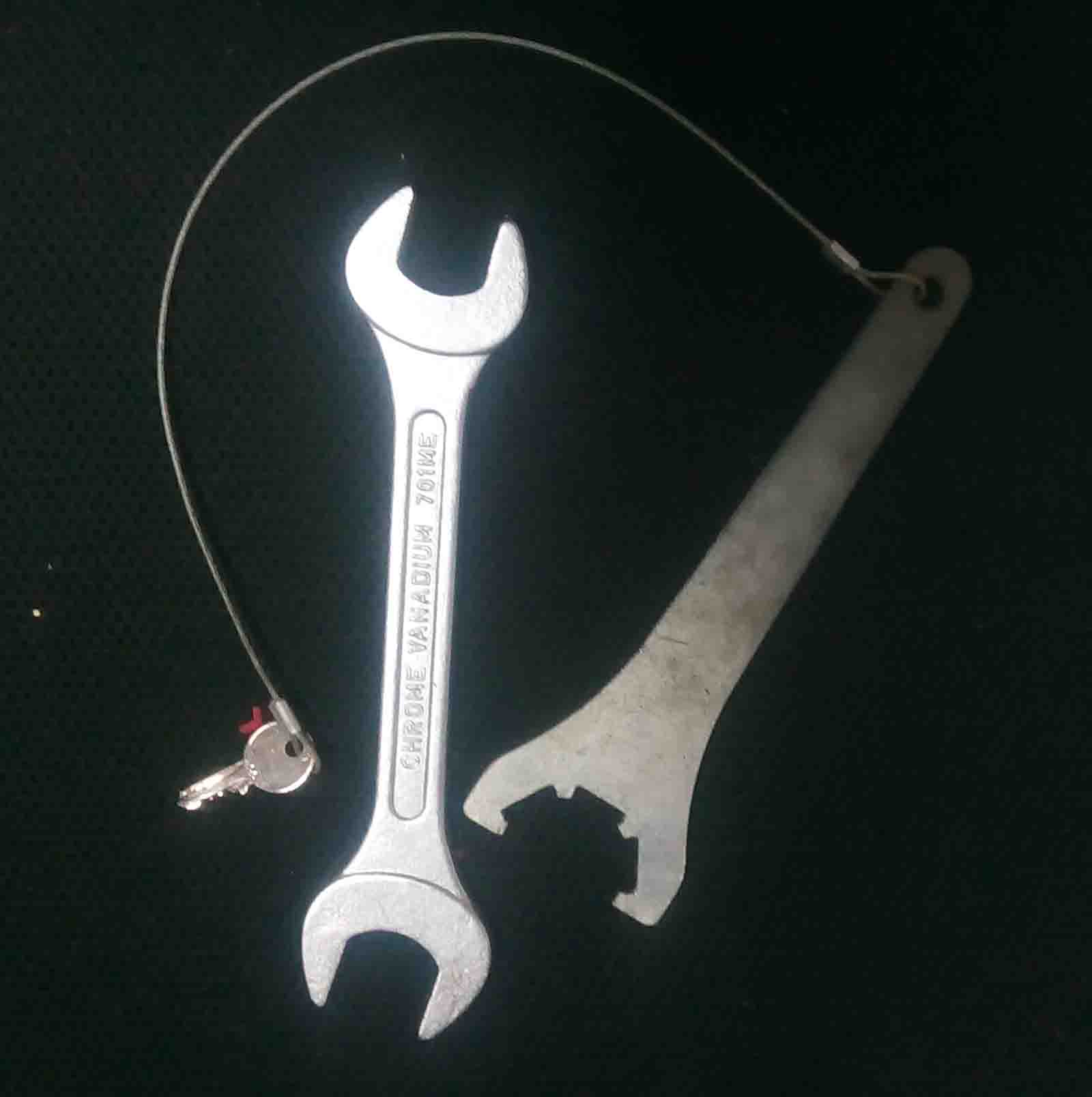
For un-screwing place the spanner and the tool in their place and rotate inwards.
Now take a 6mm end mill and it's "Collet"
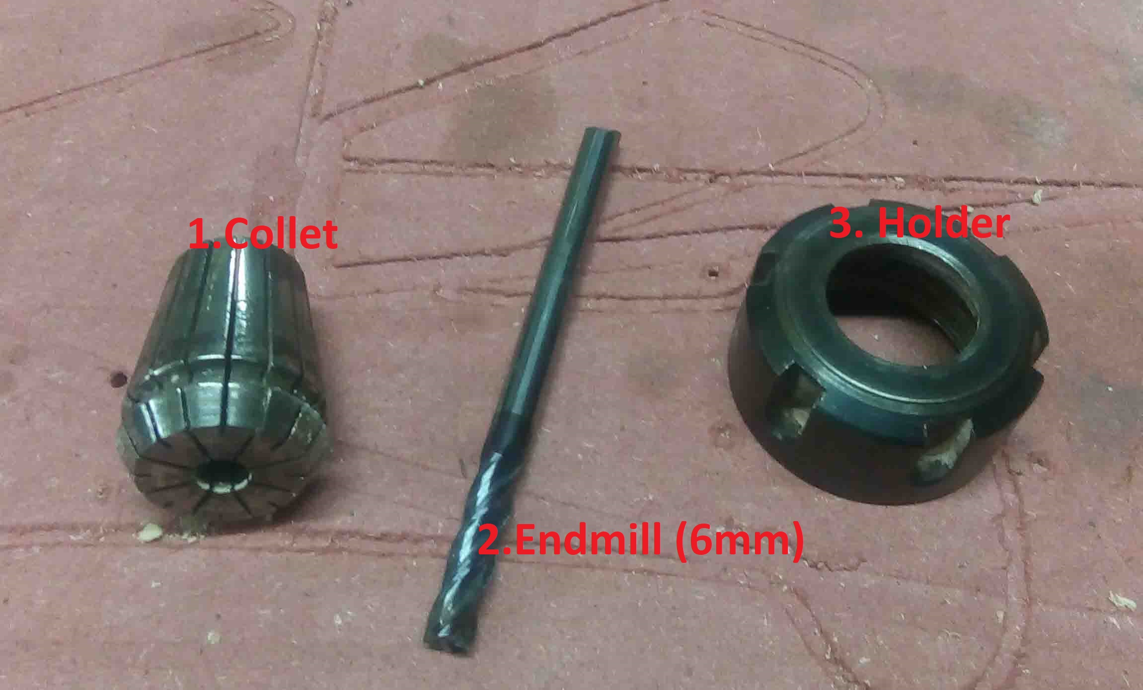
Now Insert the collet to the holder then the bit into the collet.
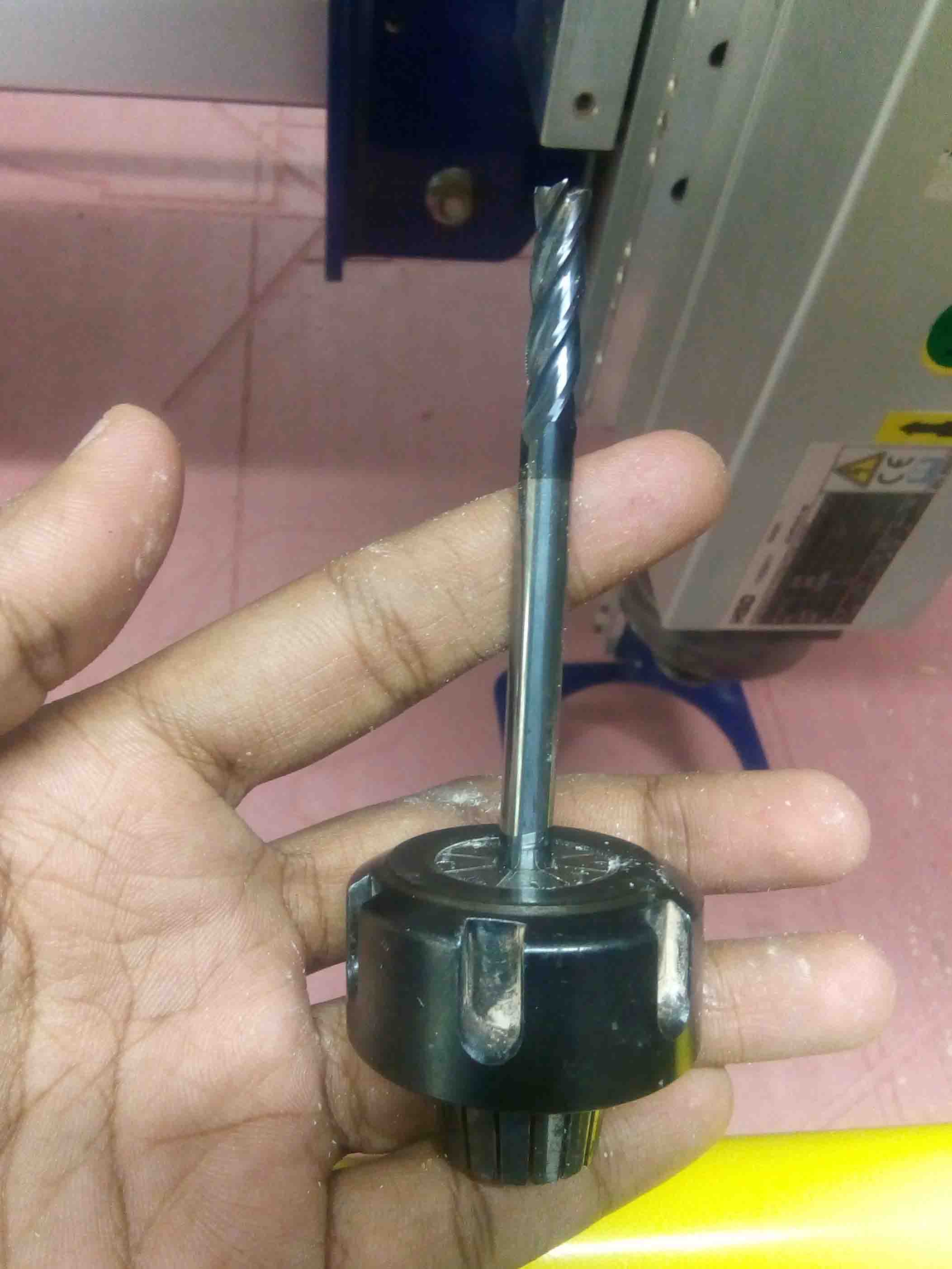
Now place the collet into the drill and rotate outwards to tight the screw. After that, put back everything back to gether.
Now place the wood on to the bed..
Cutting
So we have prepared the work piece. Now we need to cut it. for that open CNC controller.
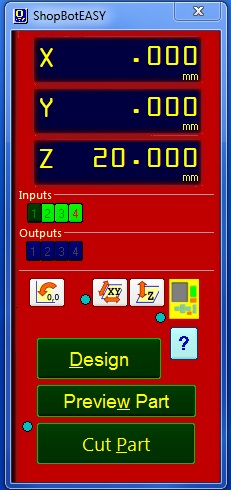
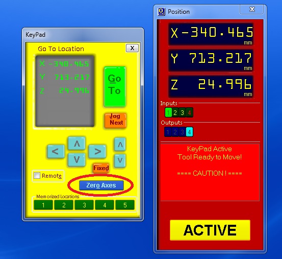
Now we need to reset the axes from the previous work. For that twist the controller in the control box and push Reset button.
Now open position control box and set X,Y and Z axes. Click on zero axis and tik all the boxes.
Now we need to add the dfile needed to be cut. For that click on "Cut Part". Open the first file and follow these steps.
I added the drill holes first to fix the work piece to the bed. After the milling I drill some holes and screw the work piece to the bed.
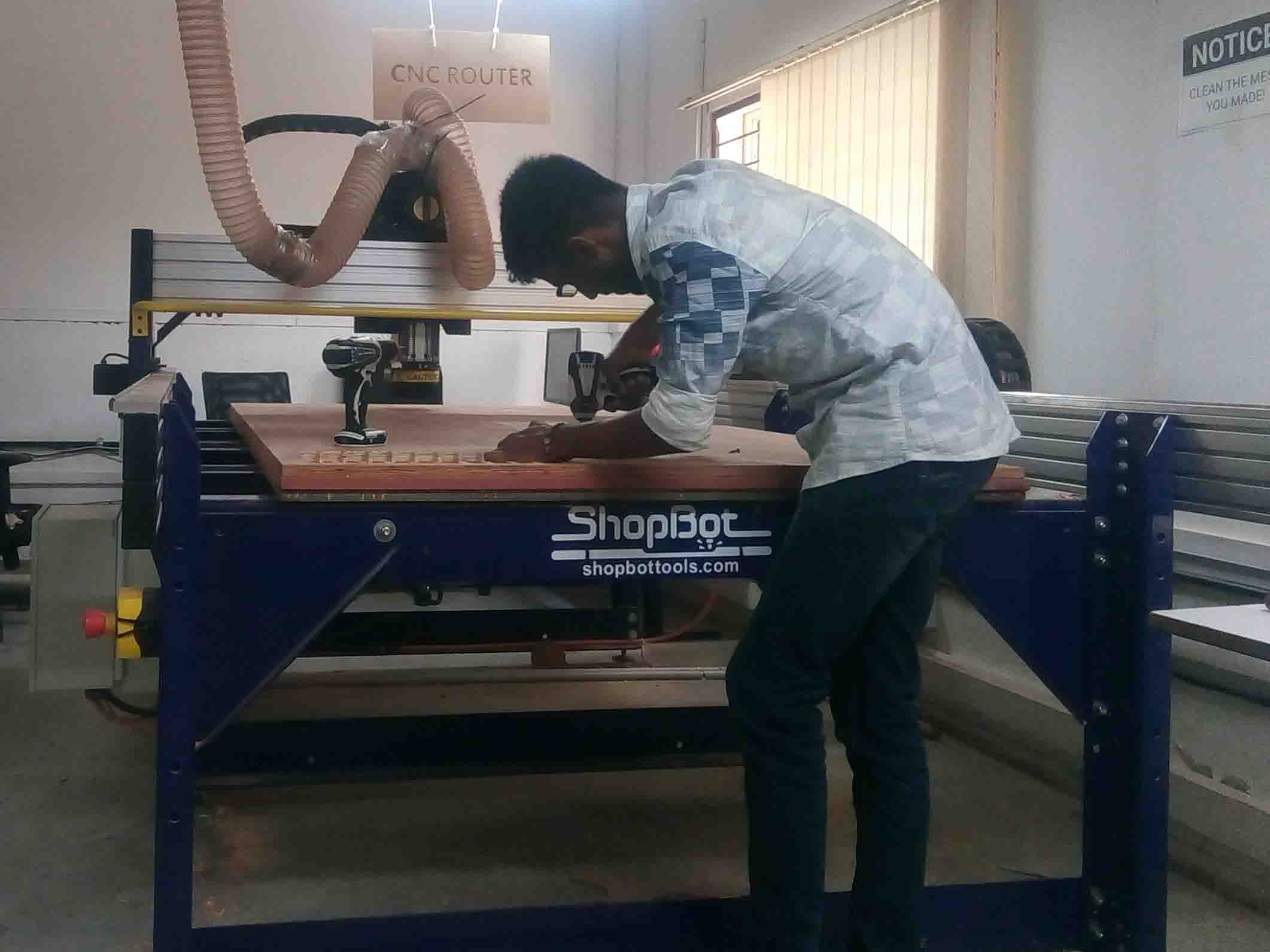
After fixing them to the bed, I started milling the rest of the pieces.
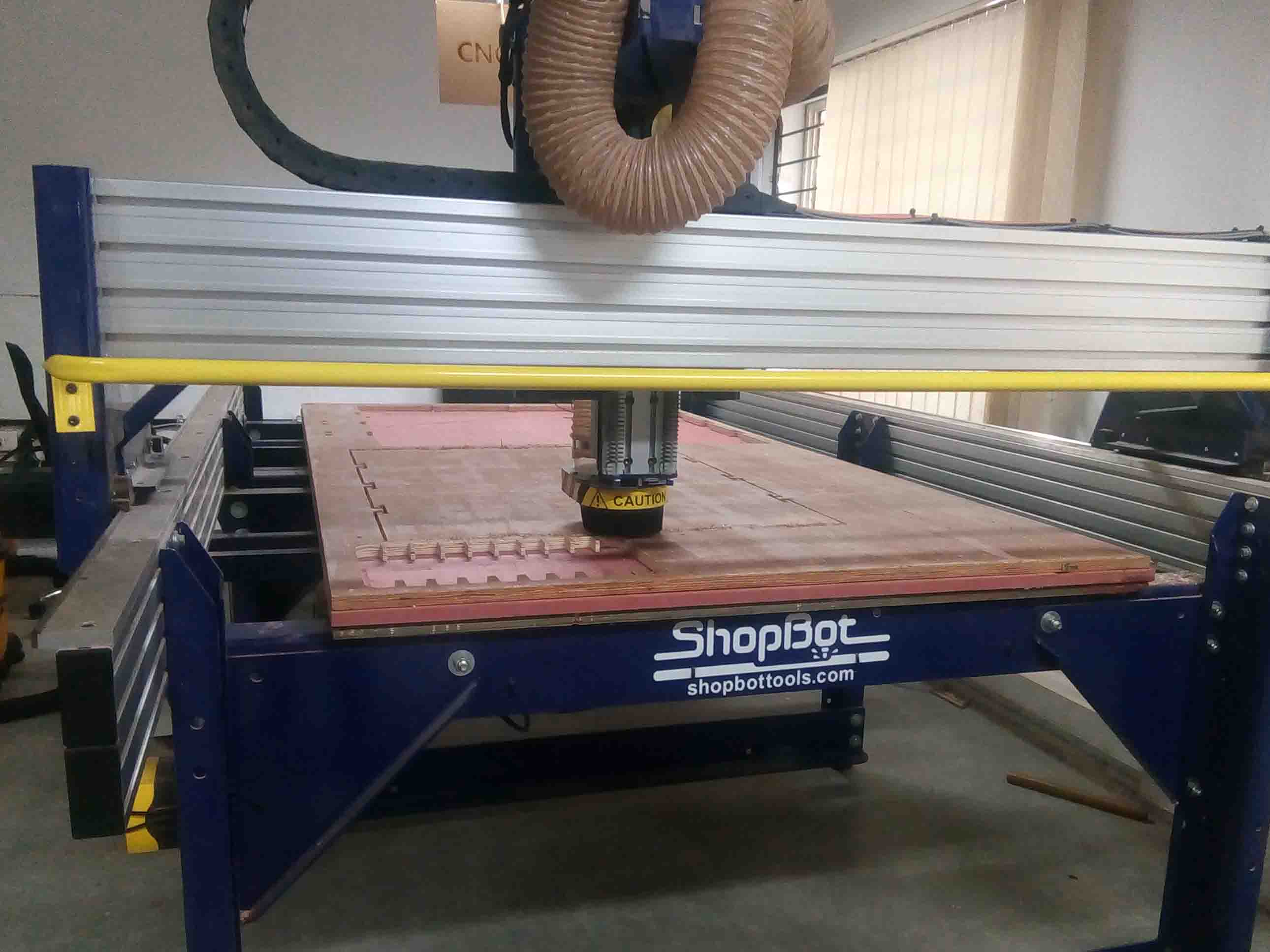
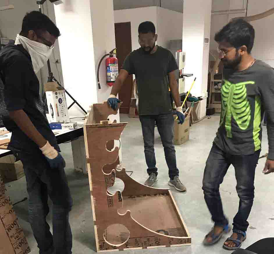
The Top, Front, Back and Base pieces are milled out Correct. Now I need to mill the side pieces in a different work piece.
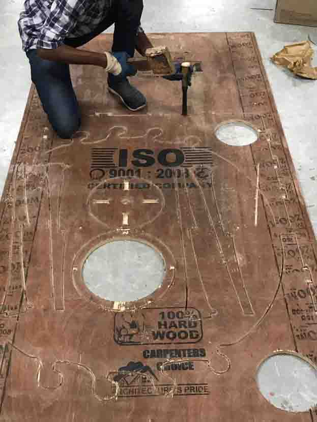
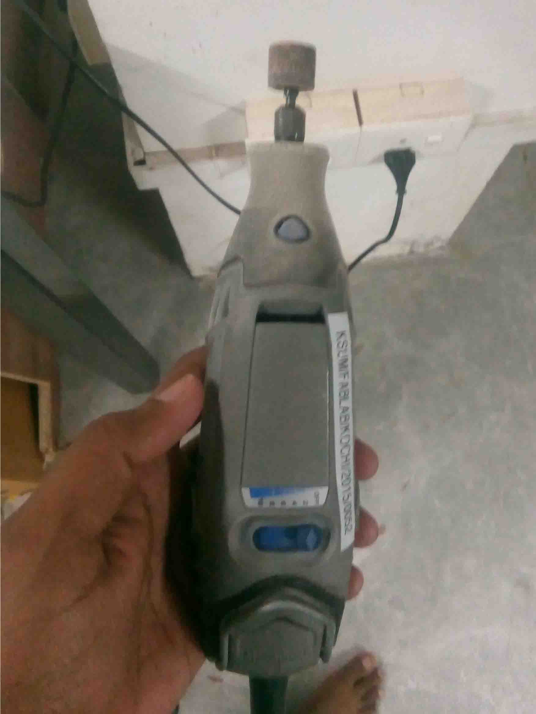
The side pieces are not cut out as I commanded it. Due to power failure the was about 2 mm wood that didn't cut off from the work piece. So I have used a chisel and a dremel handrill to cut off exess wood.
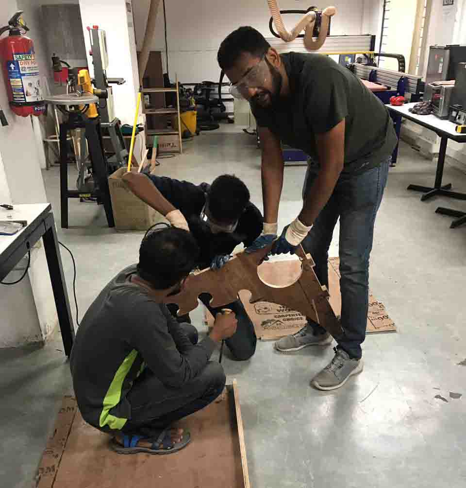
The cut off pieces was not fitting into each other. So I used dremel to sand the edges.
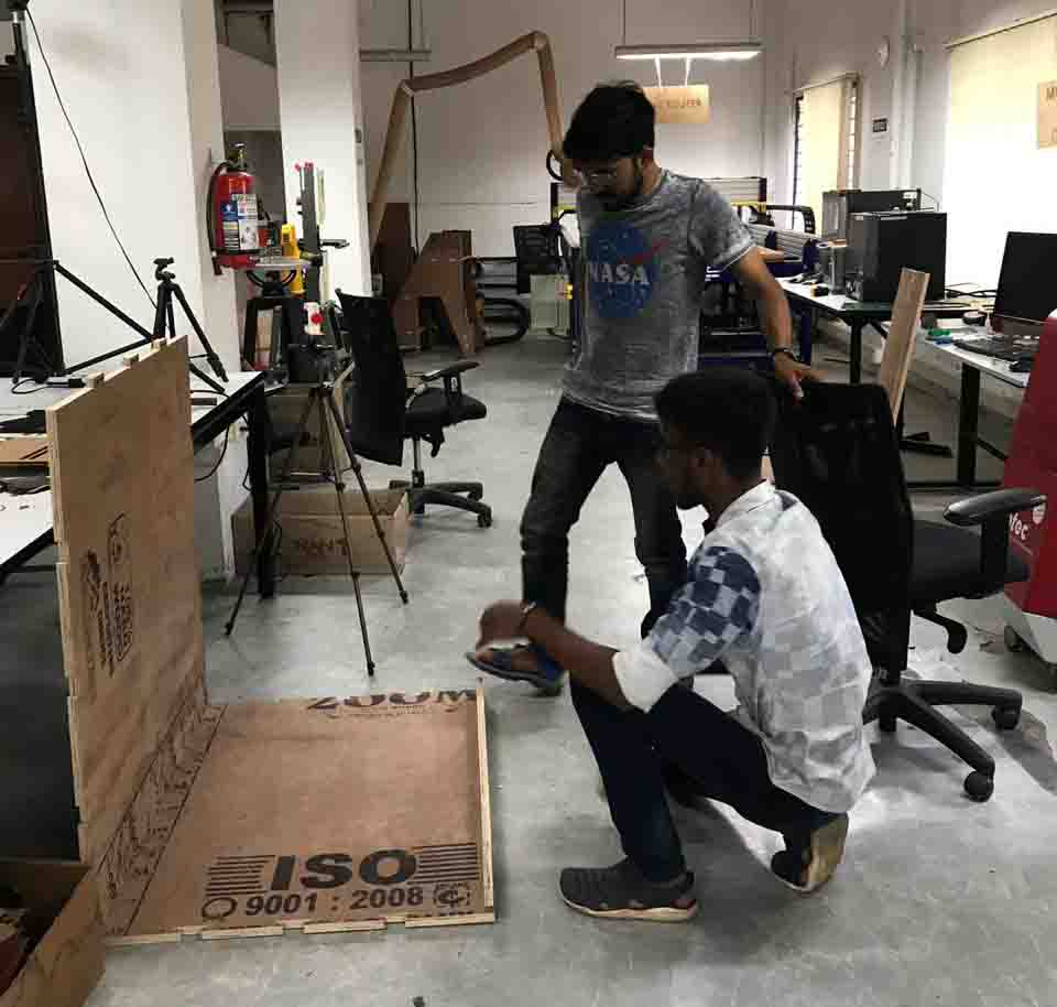
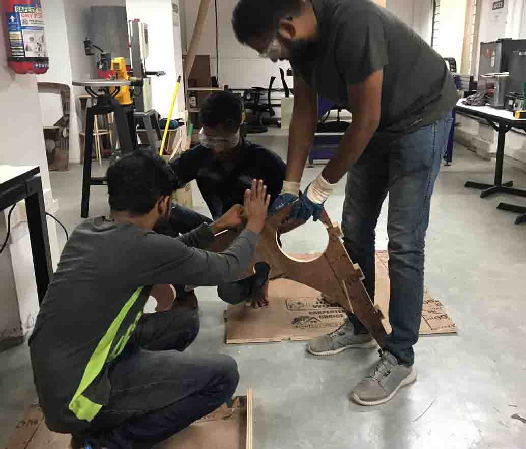
I could'nt do the assemble the pieces alone. Because the size of the pieces were large. So my friend helped me to assemble the parts.
Here is a video..
The "Vinyl Holder" was a bit large and heavy than I imagined it would be but it accomadate everything perfectly..
Hero Shot