Week 5 Electronics production
This week we had a group and individual assignment.
Group assignment
Our group assignment for this week was to characterize the design rules for our PCB production process. The machine that used is the Stepcrfat 300. In the beginning we had a lot of issues with this machine (bitts breaking etc.)but in the end it went well. The software used for this machine is WinPC-CN USB. For more info click here
Individual assignment
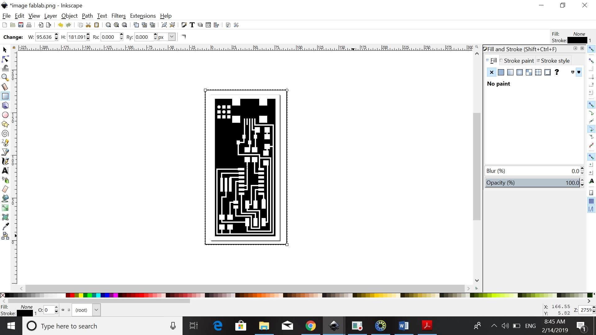
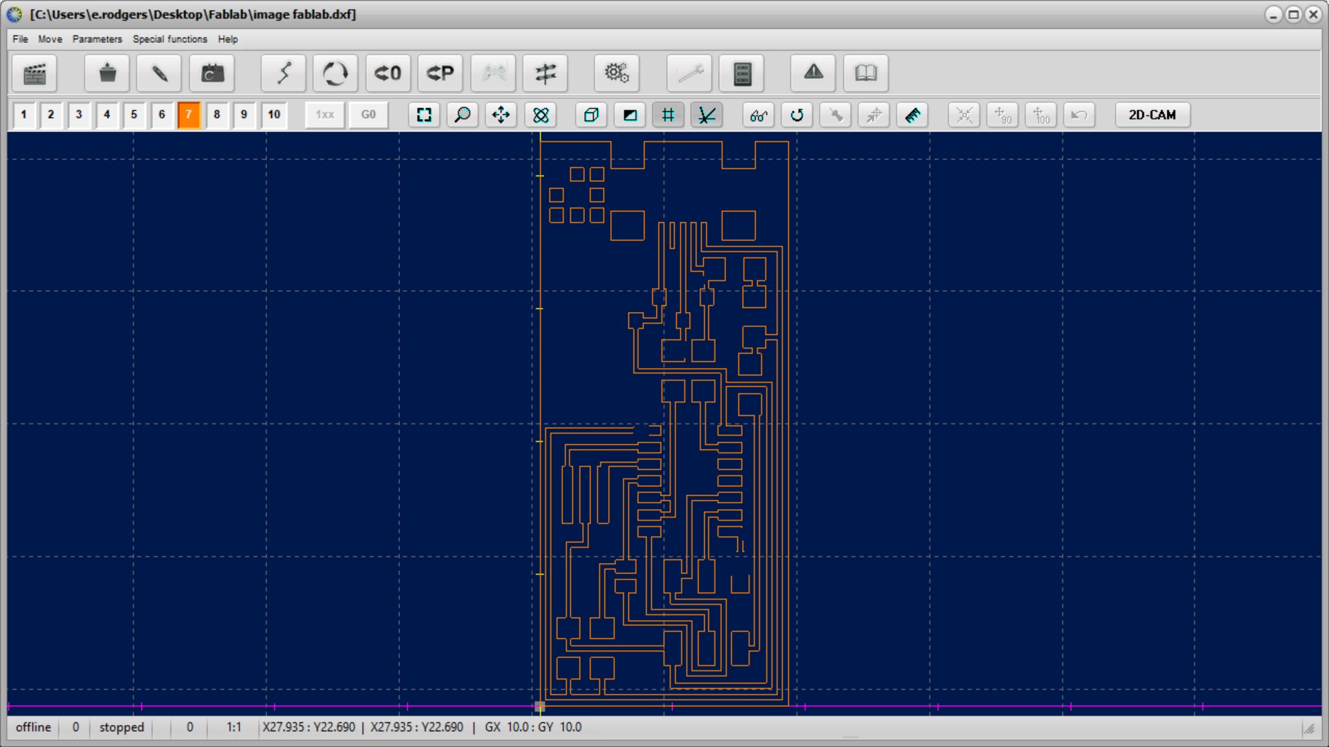
For our individual assignment we had to make an in-circuit programmer by milling the PCB, program it, then optionally try other PCB processes. First of all I downloaded the traces file belonging to hello.ISP.44.res.cad. I then opened it in InkScape did the following steps
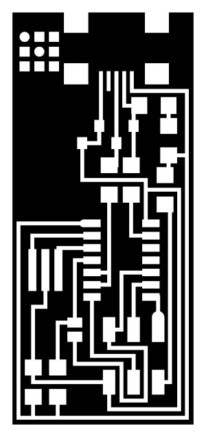
- Path/Trace Bitmap/remove fill/fill/view/default/remove original/
For the border
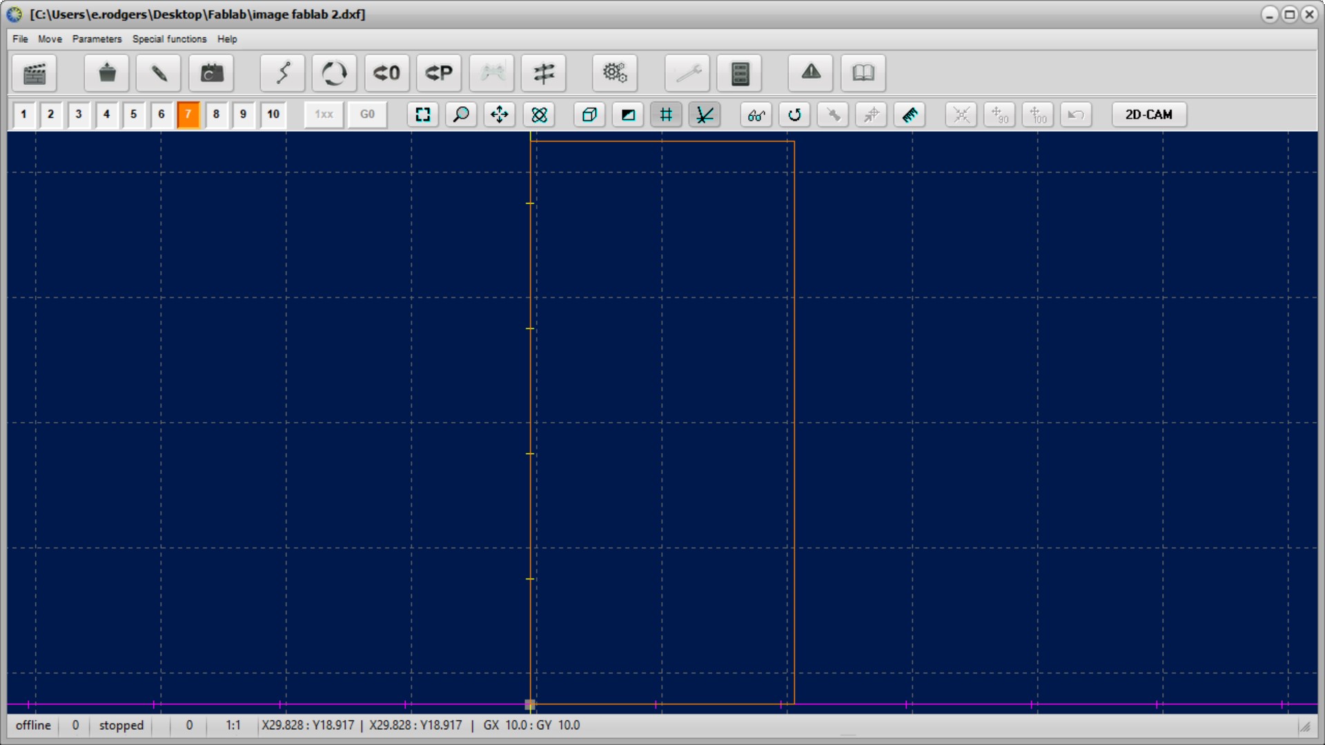
- make a rectangle/horizontal/center horizontal/select objects/remove border- save as DXF (inside traces)
- remove inside- save as DXF (outside borders)

I downloaded WinPC-NC USB and FlatCAM on my computer and used Flatcam to import file from dxf to gerber object.
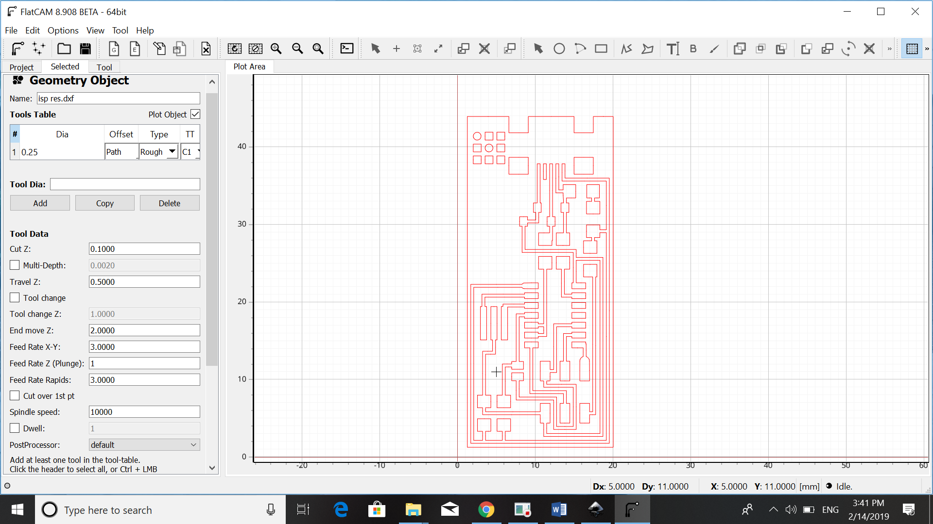
In Flatcam I changed the following parameters
-
Cut Z: - 0.15mm
-
Travel Z: 2.5mm
-
Feed rate: 0.5mm
-
Tool diameter: 0.4mm
-
Spindle speed: 10000rpm
After that I opened WinPC-NC and openened my cnc file in it. The machined that is used is the Stepcraft 300 CNC. Please note that the file must not be open, when the machine is connected to the computer.
Using the tools option, I changed the paramaters to
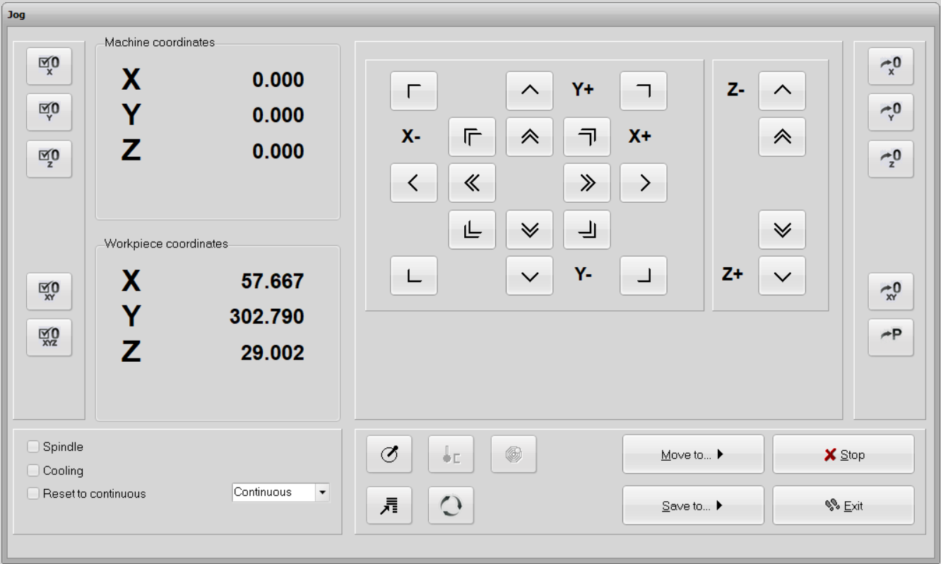
Under the tab Move, I used Jog the change the position of the mill.
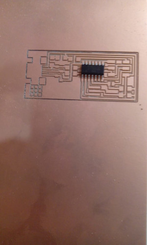
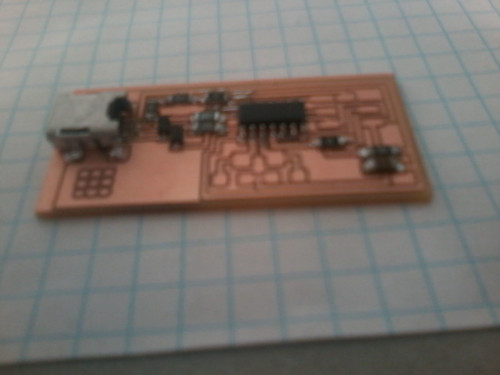
After my board was milled I had this result
Soldering
After the PCB has been milled. I went on to solder the components on the board. The components that we had to solder were
MCU: ATiny 44A. Diode, x2. 1K Resistor. 10K Resistor. 20MHz Resonator. 0 Ohm Resistor, x2. 1uF Capacitor. 10K Ohm Resistor. ATMEL Ice Programmer. (AVR ISP)
To solder the components we needed a pincet(some componnets are really small), flux, soldering paste and of course our solder with its attributes. To get the best result apply paste to the part of your component that will be soldered. This helps the solder to run smoothly from you component to the board.
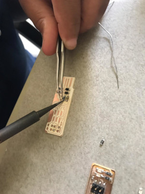
 The result
Programming
Programming the board didn’t go well. My instructor helped me with that but the board refused to react.
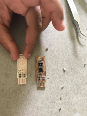
Trial 2
For the second trial we got a board from our instructor. This programmer is based on Brian ISP.
The components we used for this programmer are:
1x ATtiny45 or ATtiny85
2x 1kΩ resistors
2x 499Ω resistors
2x 49Ω resistors
2x 3.3v zener diodes
1x red LED
1x green LED
1x 100nF capacitor
1x 2x3 pin header
Programming
To program this board we used linux, the steps we took were:
- enter command: sudo apt install avrdude gcc-avr avr-libc make
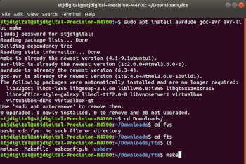
- download firmware source code and unzip unzip fts_firmware_bdm_v1.zip
- run make, you get a file called fts_firmware.hex. You will see this new file in your Unzipped firmware folder
- update the Makefile in notepad or wordpad
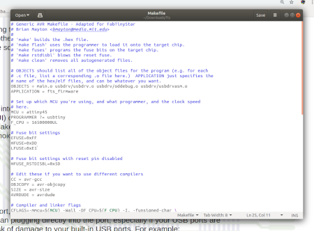
- Near the top of the file, find the line that says: PROGRAMMER ?= usbtiny
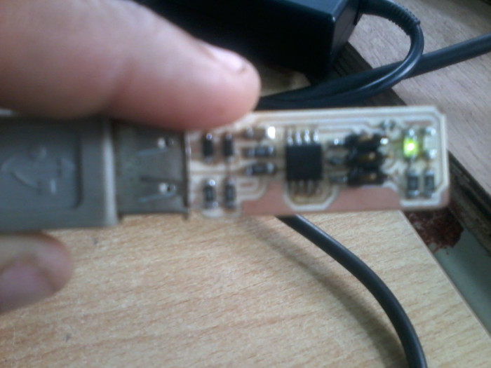
- Plug the board into the USB port, the LED will light up
- Run make flash
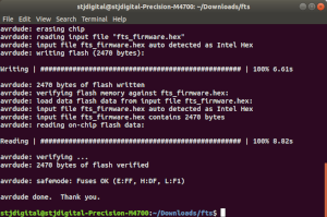
- Run the make fuses
- Type lsusb in the terminal
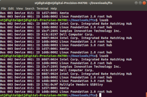
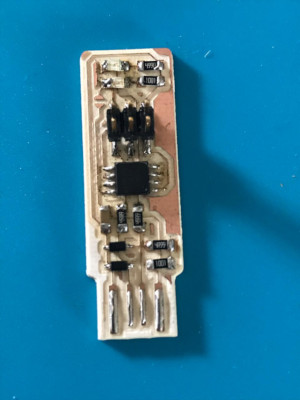
The result of my programmer (It is working)