Week 11 Input devices
This week we had a individual and group assignment.
Group assignment
For our group assignment we had to probe an input device’s analog levels and digital signals. For more info about this weeks group assignment you can click on this link.
Individual assignment
The individual assignment was to measure something: add a sensor to a microcontroller board that you have designed and read it.
Designing
The components that I used for this assignment are:
-
Attiny45 microcontroller
-
Resistors (2) 499, (2) 10K
-
AVRISPSMD, 2x3 header
-
LED blue
-
LED red (power)
-
FTDI pinheader 1x6
-
Phototransistor
-
Capacitators (1)
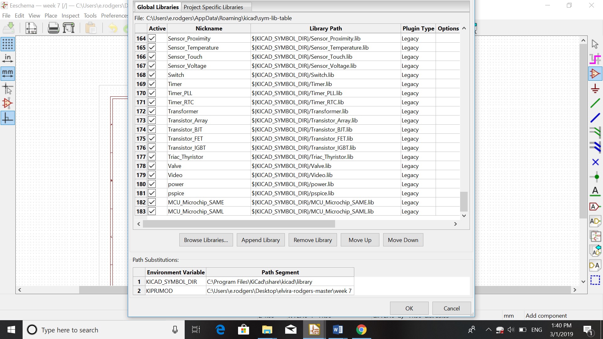
I started in KiCad by opening a new project and giving it a name. I then opened the schematic layout editor for the list of components. I opened preferences and manage symbol libraries to see the list of the libraries.
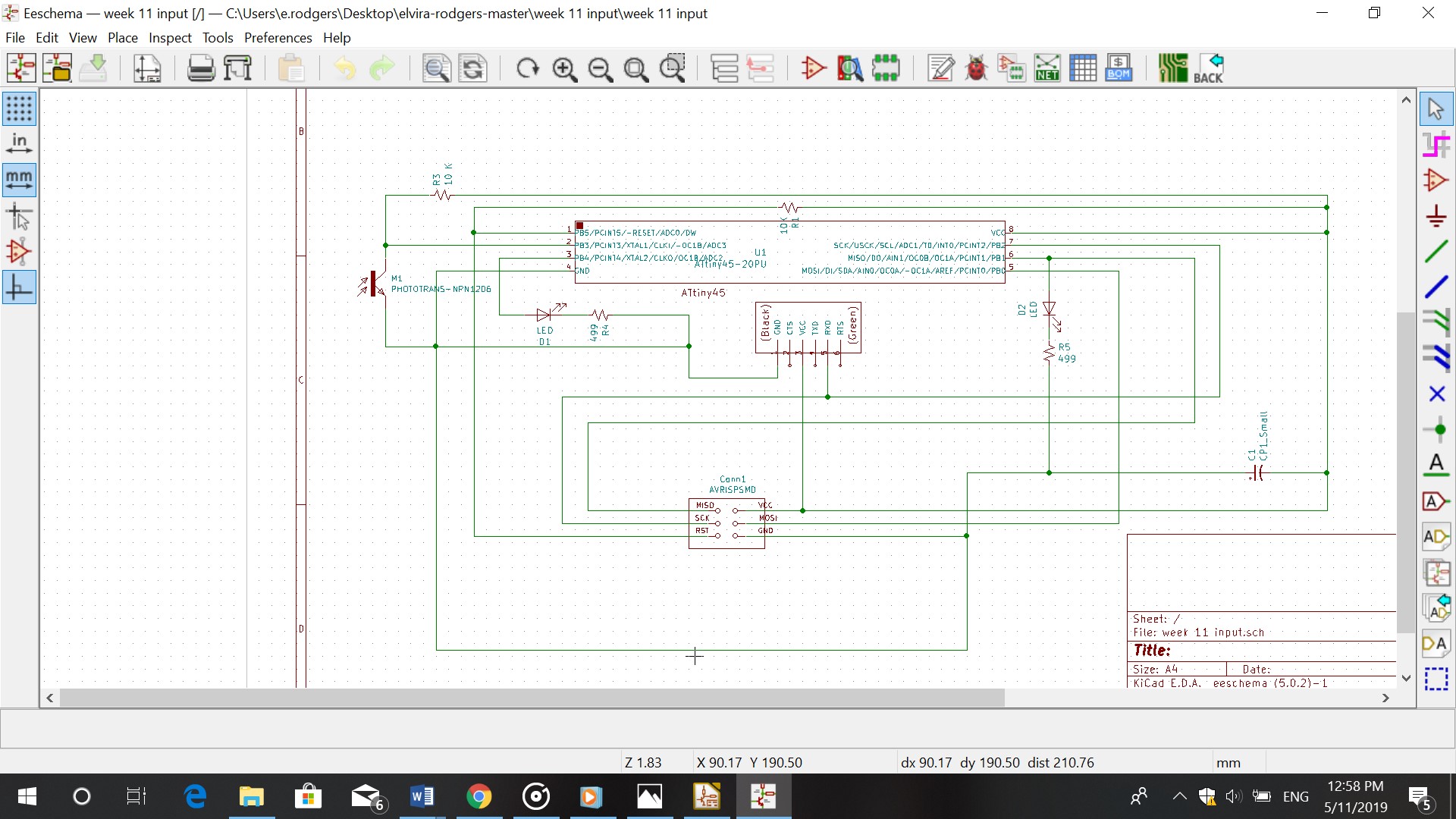
I started assigning the components to the schematic by clicking on place symbol. After assigning all the components I connected them using the wire icon.
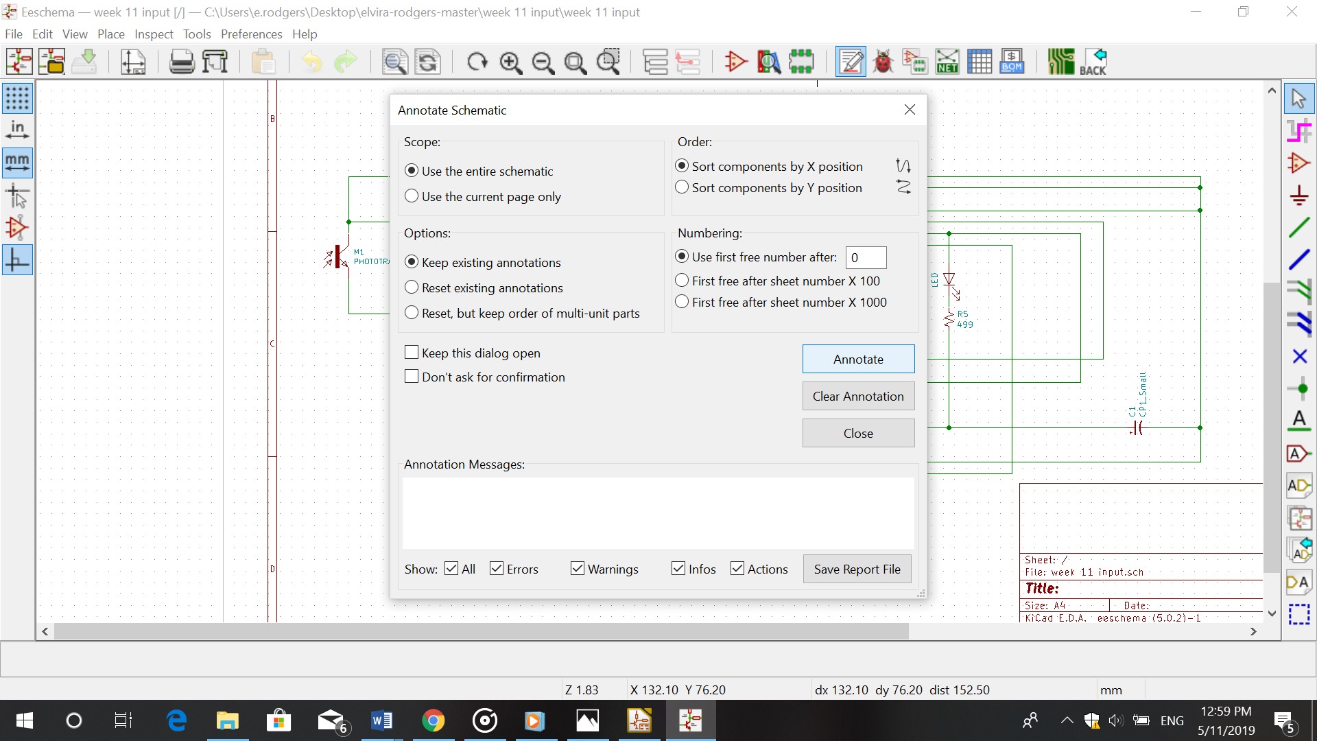
After being done with the schematic I followed these steps:
a. Annotate
b. Assign PCB footprints from schematic
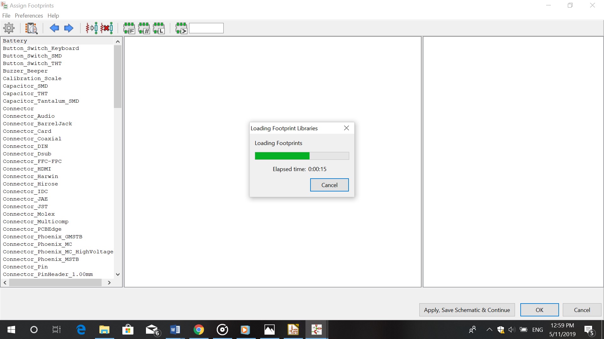
c. You get a list of components on the left. Double click on the name of the components (right) untill you have reached the last component.
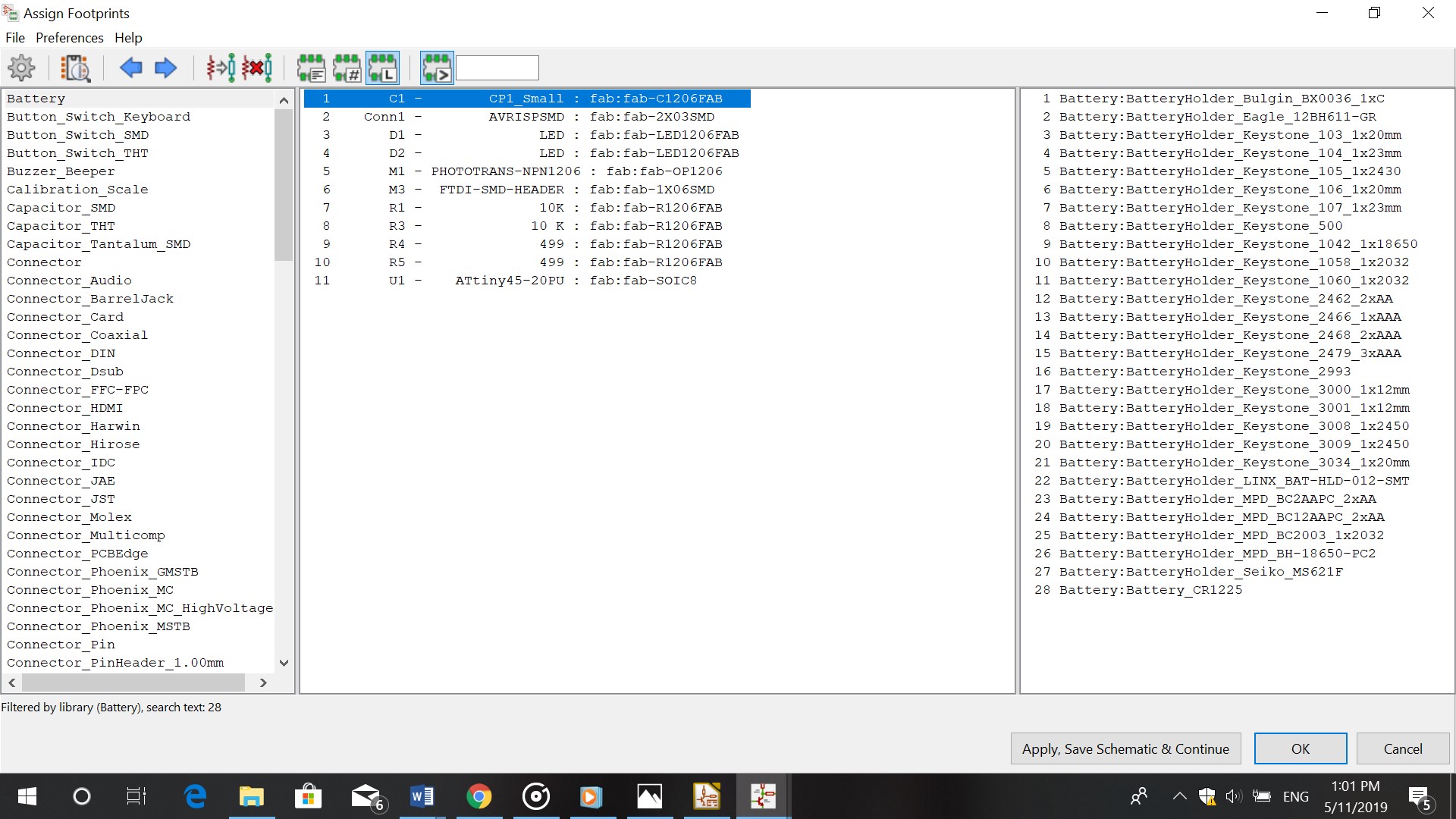
d. Click on Apply, save schematic and continue- ok
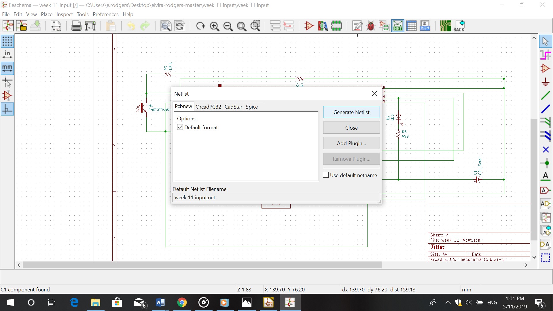
e. You then generate the netlist and save it in your file
f. Tools- Update PCB from schematic
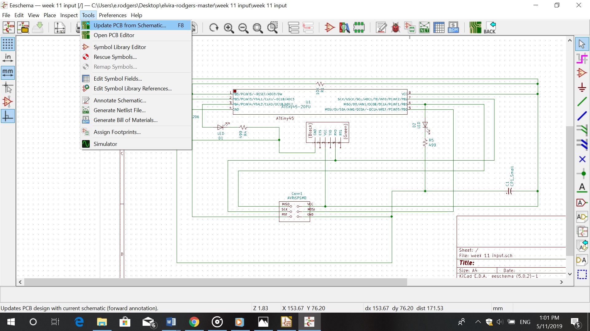
g. Make sure you don’t have any errors or else the schematic won’t match the board.
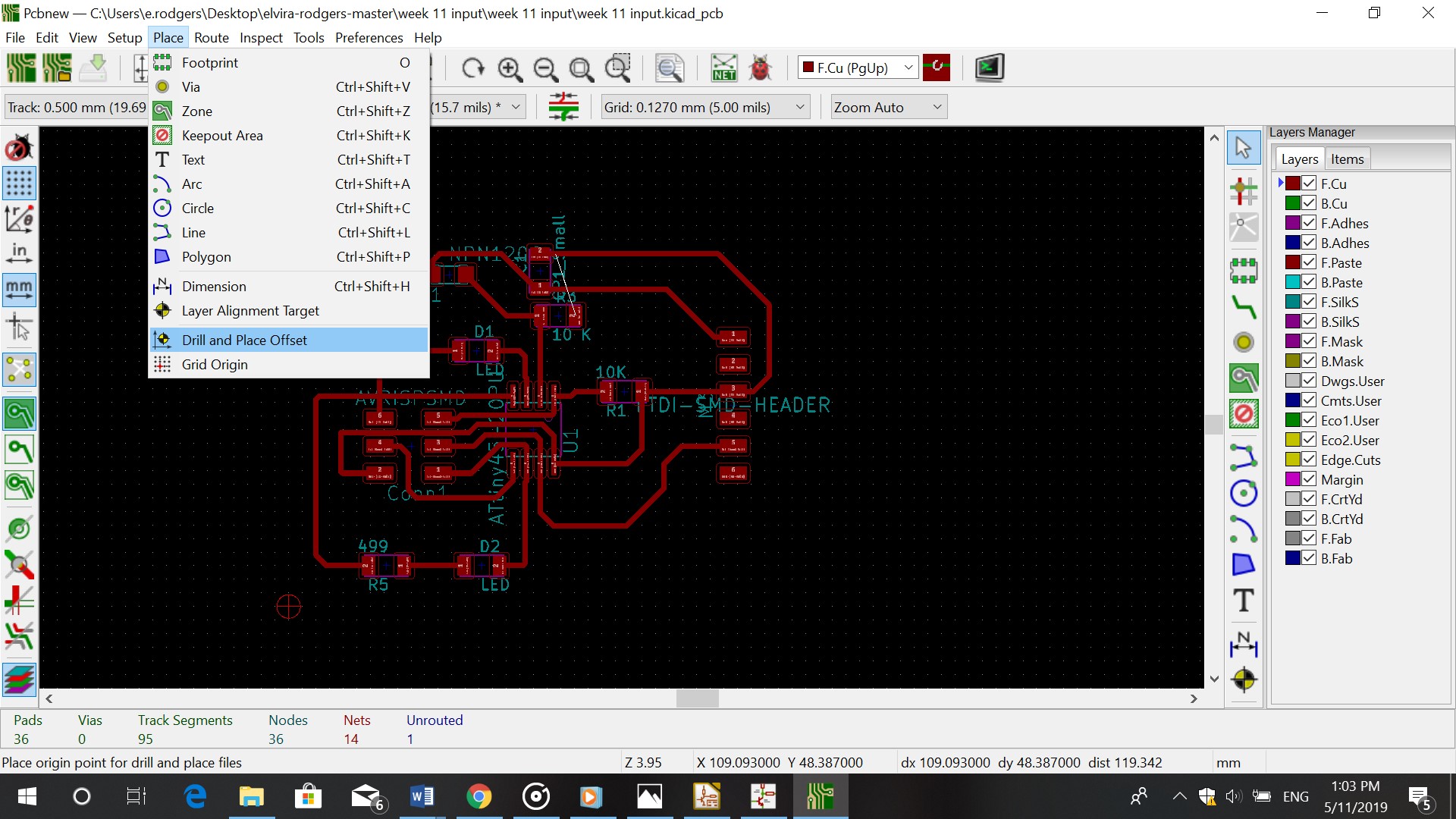
After generating the schematic I placed the tracks in it.
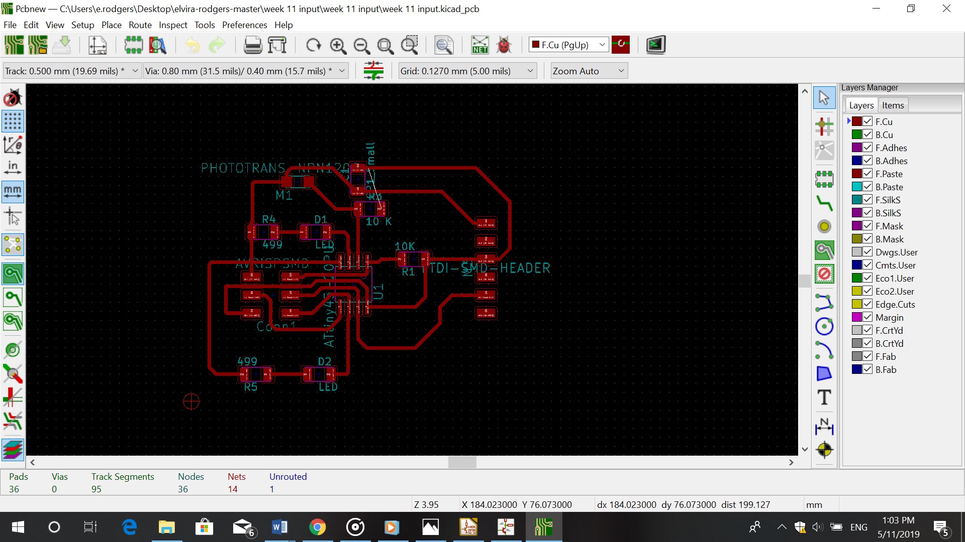
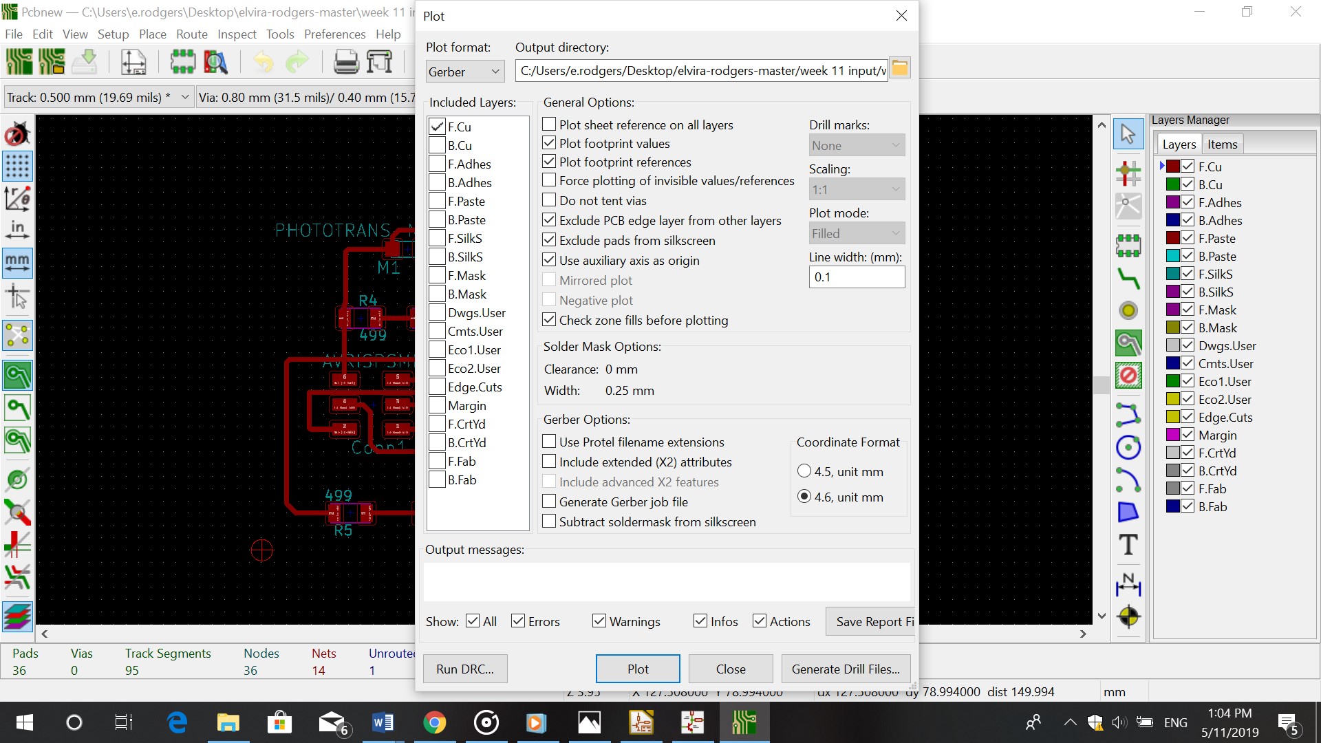
I then clicked on File-Plot-Generate Drill files, to generate the files.
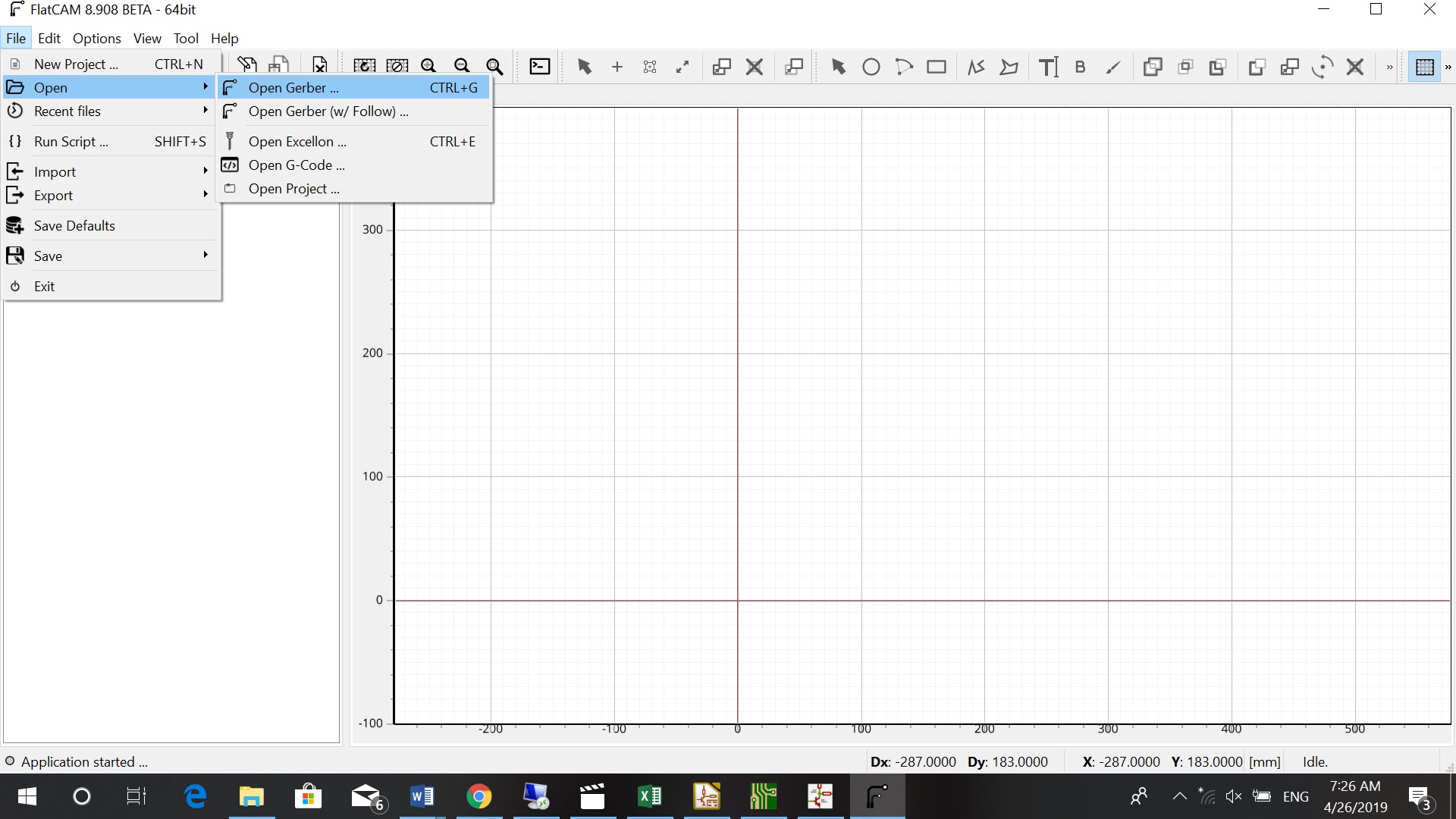
Flatcam
Tracks
I opened the Gerber file in FlatCam (the one ending with F.Cu.gbr)
In project I double clicked on the name of the Gerber file and set the parameters
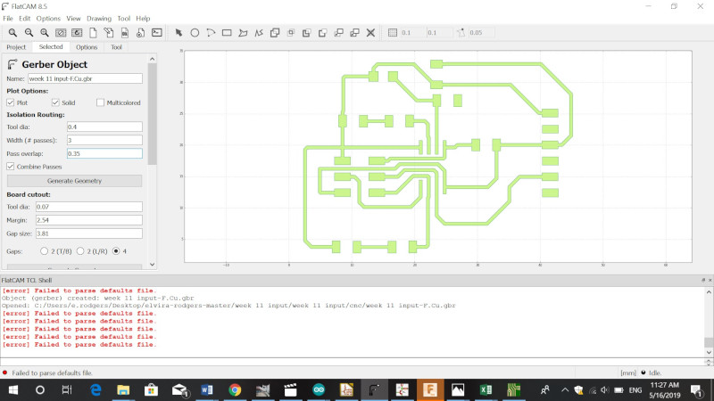
Tooldiameter: 0.4 mm
Width (passes): 3
Pass overlap: 0.35
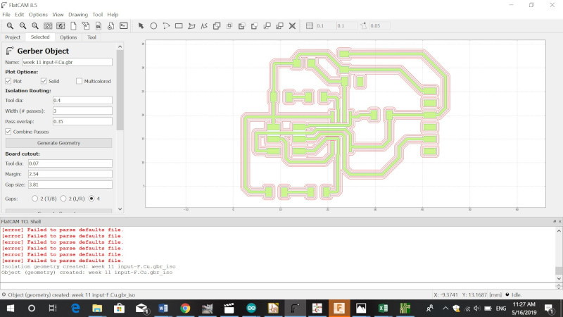
I then generated the Geometry
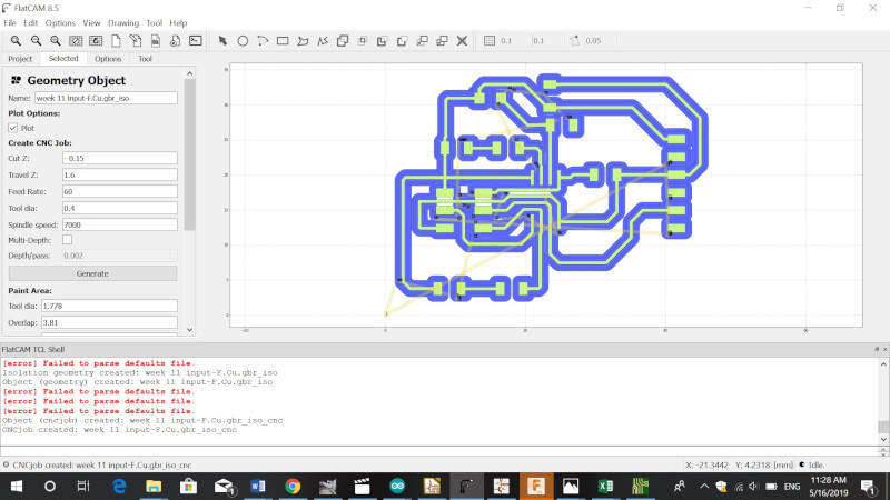
I went to project again and clicked on the file ending with _iso
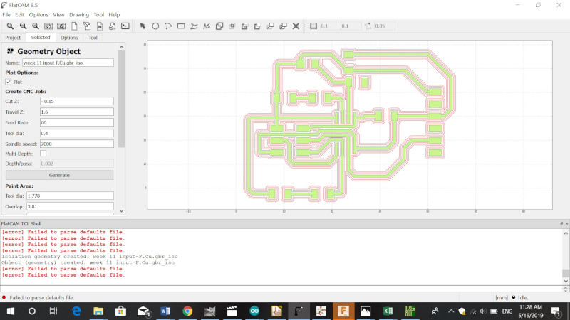
The parameters that I used are:
Cut Z: - 0.15
Travel Z: 1.6
Feedrate: 60
Tooldiameter: 0.4
Spindle: 7000
I generated the file
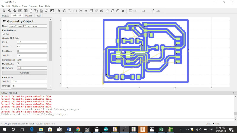
Cutout
For the cutout I clicked on the Gerber file in Project. I changed the tooldiameter to 0.8mm and generated the file.
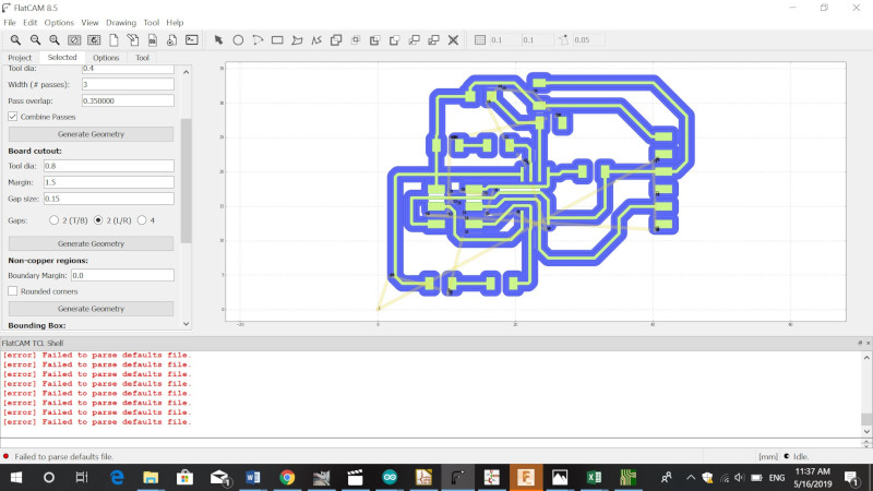
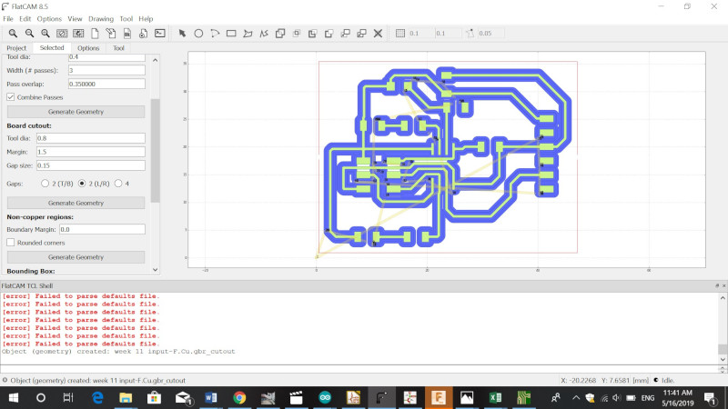
I went to project and clicked on the file ending with _cutout
I changed the parameters to:
Cut Z: - 1.6
Travel Z: 1.5
Feedrate: 30
Tooldiameter: 0.8
Spindle: 7000
Check multidepth and set it at 0.533
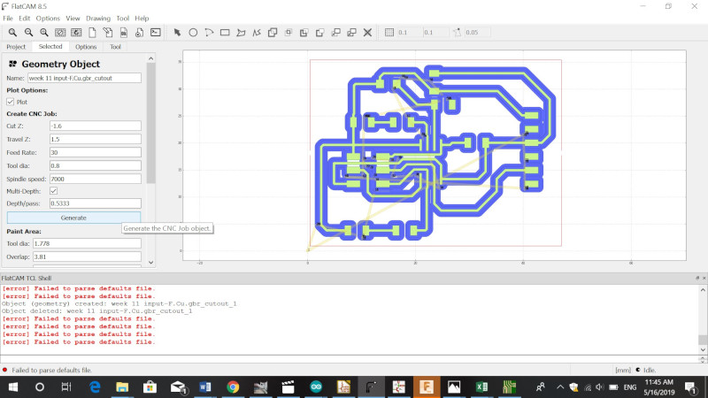
Generate
Milling
For this assignment I used a cnc machine that our co student brought
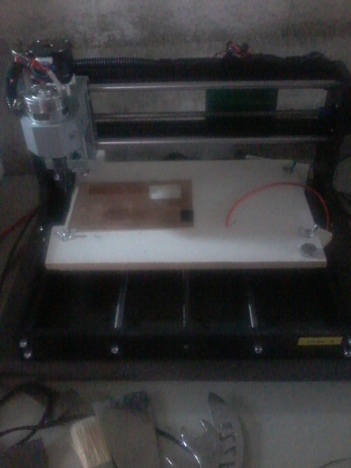
I first downloaded Candle_1.0.11 and installed it. I then opened my file in Candle. I set the X,Y and Z
Because the board can be oneven we had to set a heightmap. I used 4 for the X probe grid and 4 for the Y probe grid. This calculates the height of the board in 4 point to left (X), and 4 points to the back (Y)
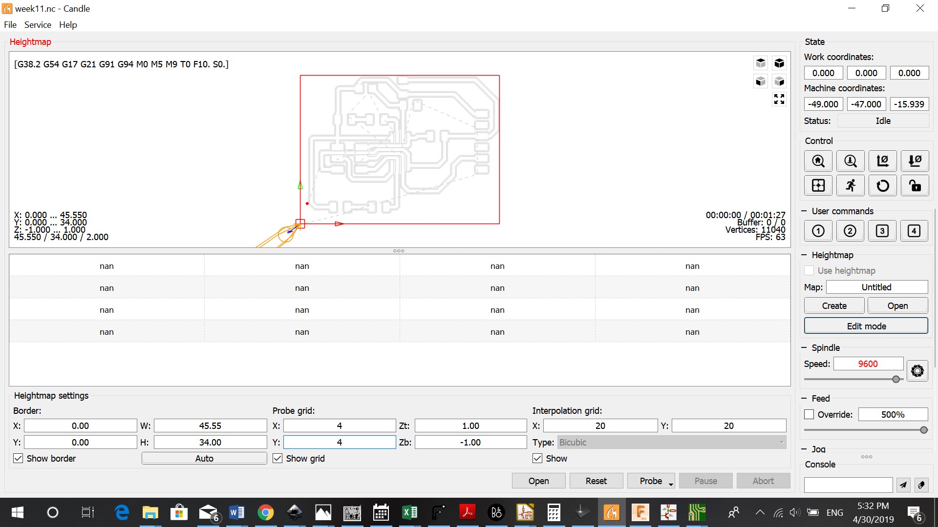
After saving the heightmap in your file. You can start milling by clicking on send.
Programming
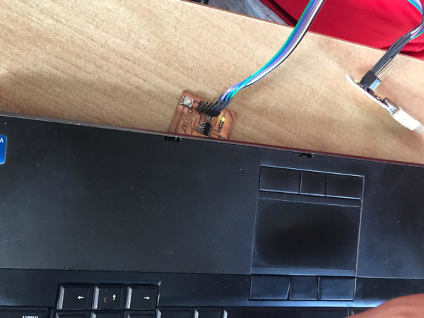
After soldering the components on my board, I used the multimeter to see if all connections were right. One of the connections wasn’t working, so we used a jumper cale to make the connections. To program the board I connected the programmer and my input board via the USB cable.
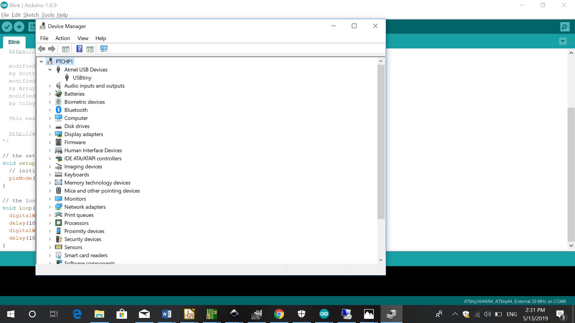
First I checked the device manager to see if USBtiny was one of the connected devices
I then opened a Blink file and in tools I changed the board to Attiny 25/45/85, processor to Attiny 45.
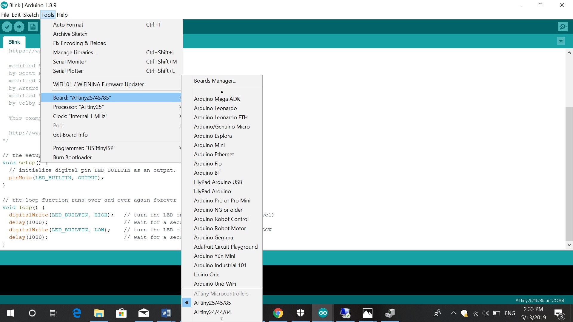
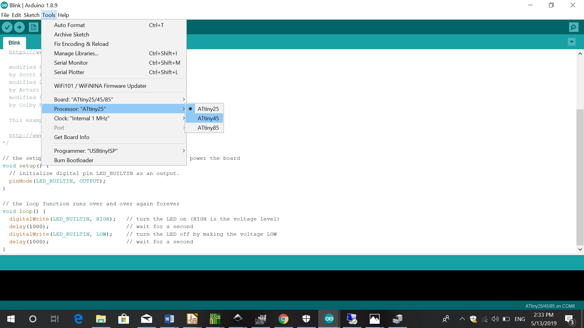
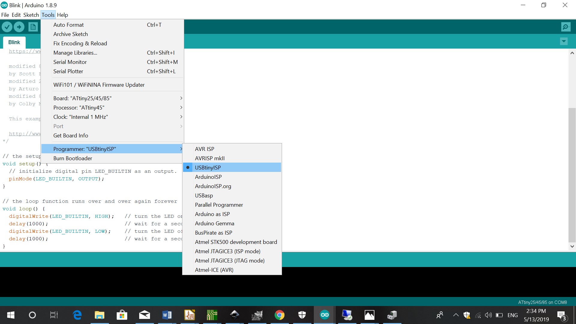
The programmer should be USBtiny ISP
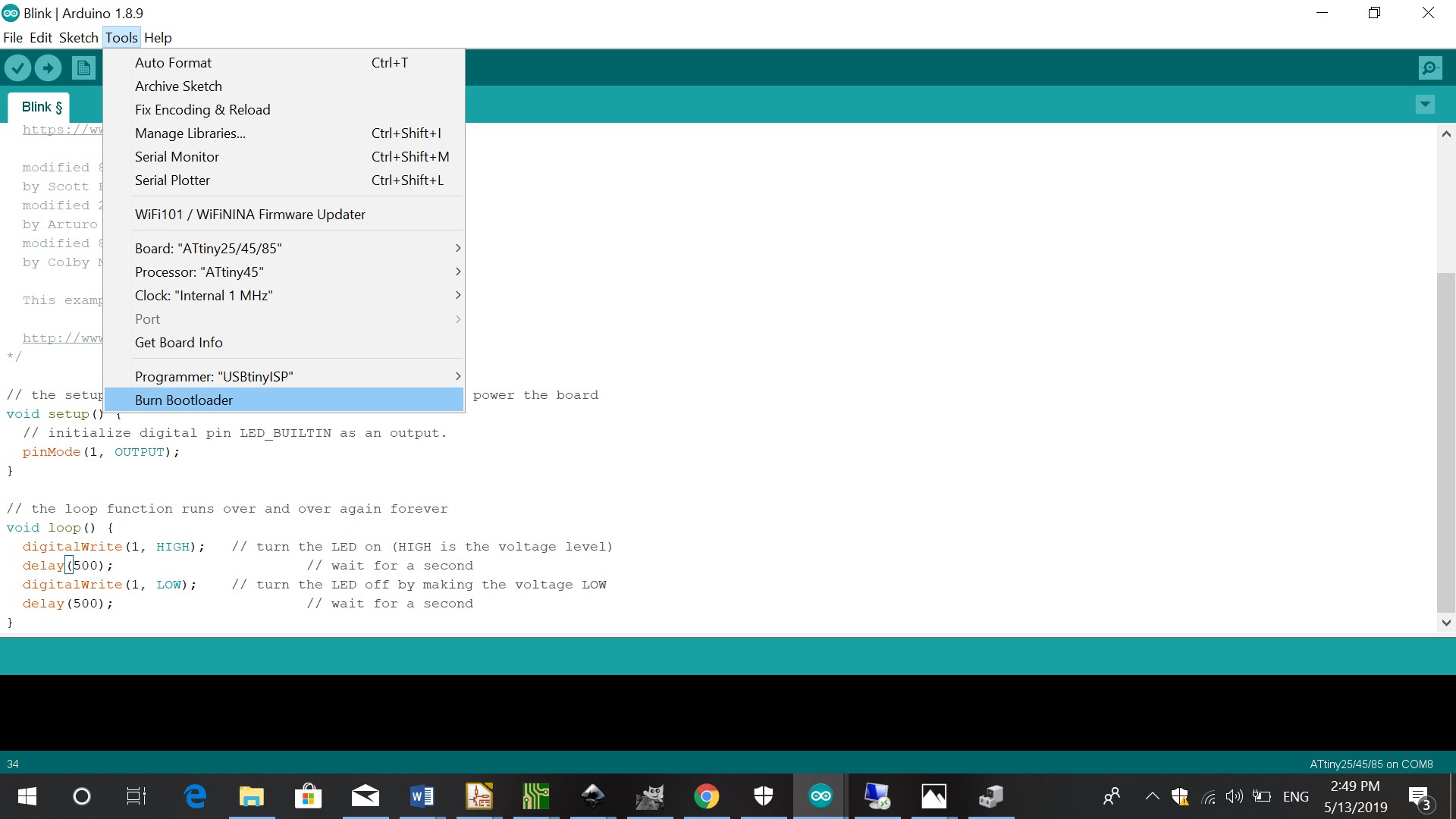
Burn bootloader
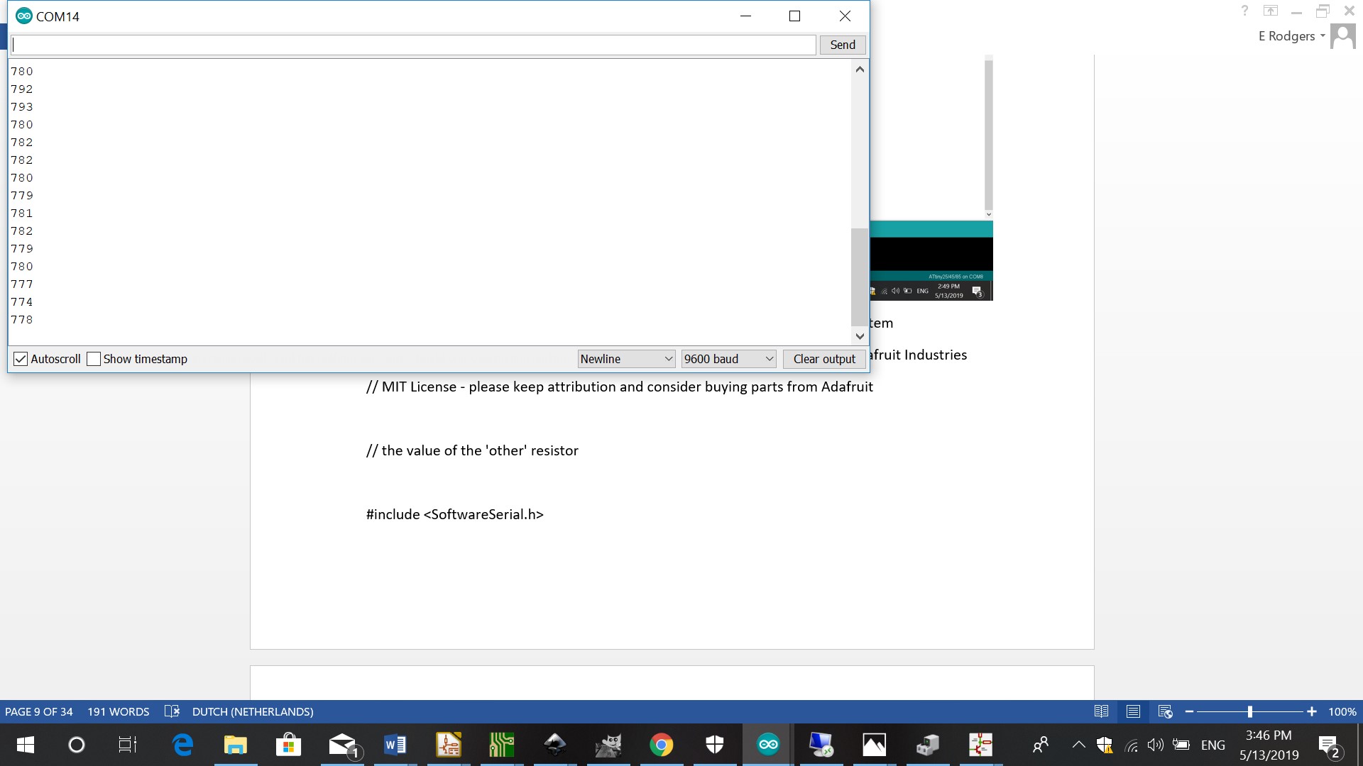
After you have burned the bootloader and there are no errors, you check the serial monitor (icon on top right corner)
I looked for the Attiny 45 pinout and changed the pins.
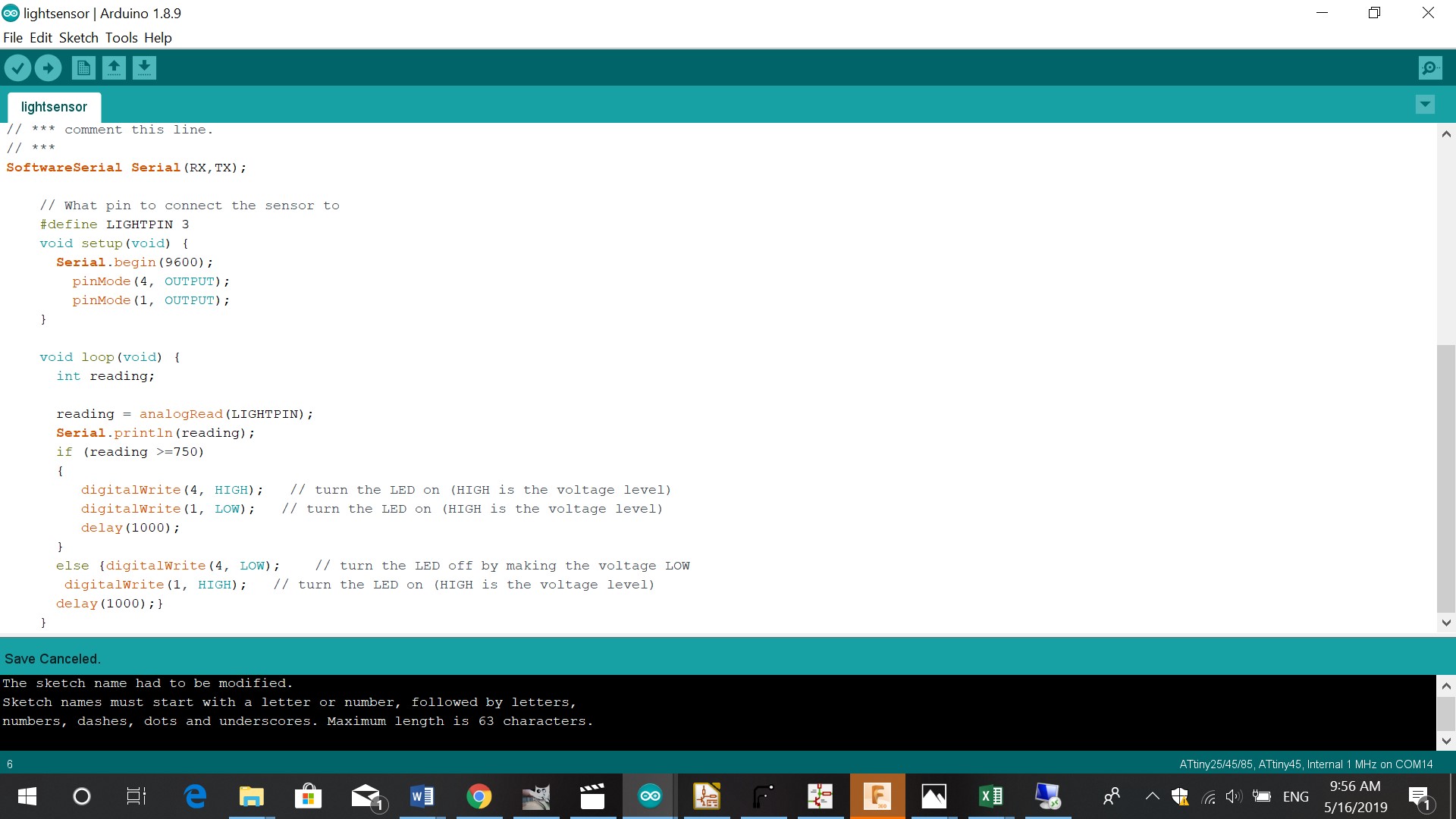
 reading = analogRead(LIGHTPIN);
      Serial.println(reading);
      if (reading >=750)
      {
         digitalWrite(4, HIGH);   // turn the LED on (HIGH is the voltage level)
         digitalWrite(1, LOW);   // turn the LED on (HIGH is the voltage level)
         delay(1000);
      }
      else {digitalWrite(4, LOW);    // turn the LED off by making the voltage LOW
       digitalWrite(1, HIGH);   // turn the LED on (HIGH is the voltage level)
      delay(1000);}
    }
The code I used for this project was based on turning the LED on or off when there is light shining above the sensor or when there is darkness above the sensor. In this case I used a red LED and a blue LED. When there is darkness above the sensor , the red LED turns on. When light shines above the sensor, the red LED turnes off and the blue one goes on. This input design is a good prototype example for my final project, because my lamp should be able to detect darkness and turn on.