11. Input devices
Group assignment
Individual assignment
Week 11 - Input
Designing the board
I decided to fabricate the light sensor as a possible feature for my final project. I started by looking at Neil’s design.
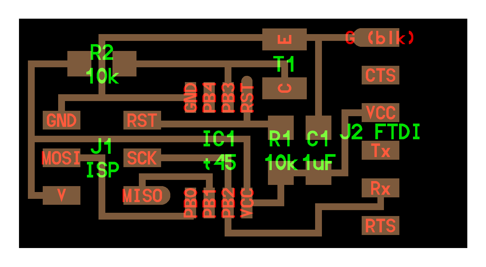
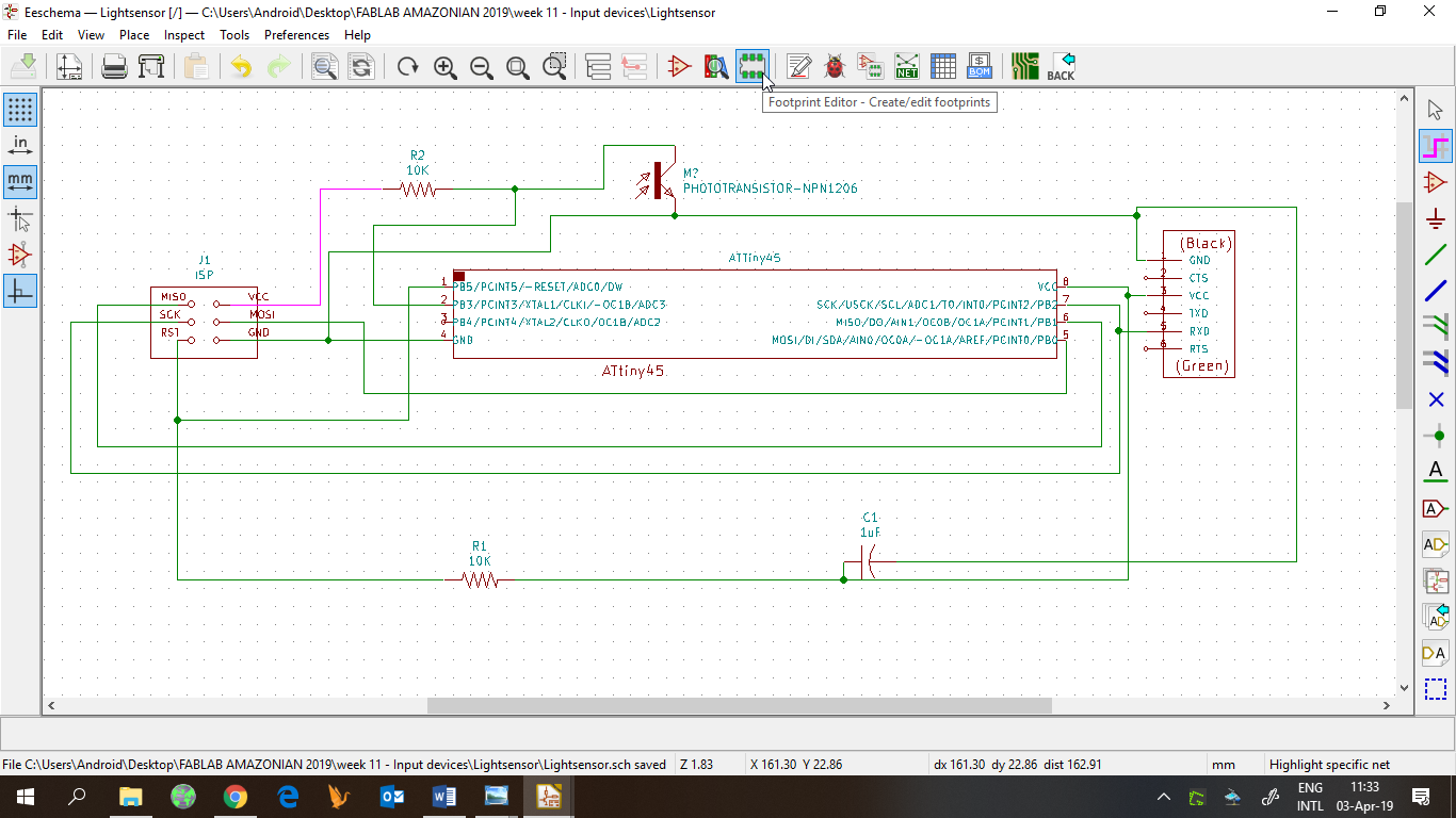
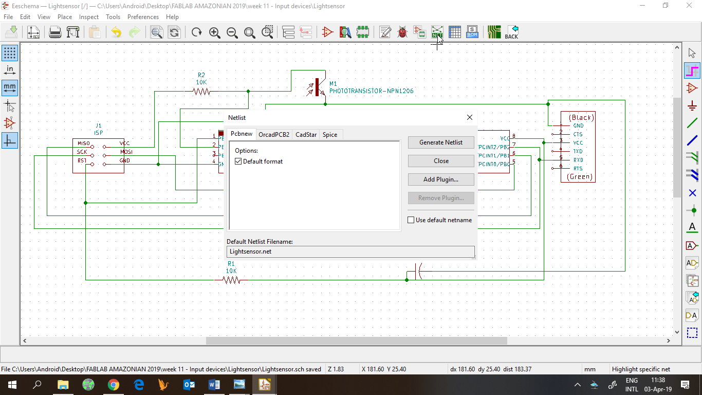
Then, I started designing my board, so I added all required components in Kicad Eeschema and make the proper connections.
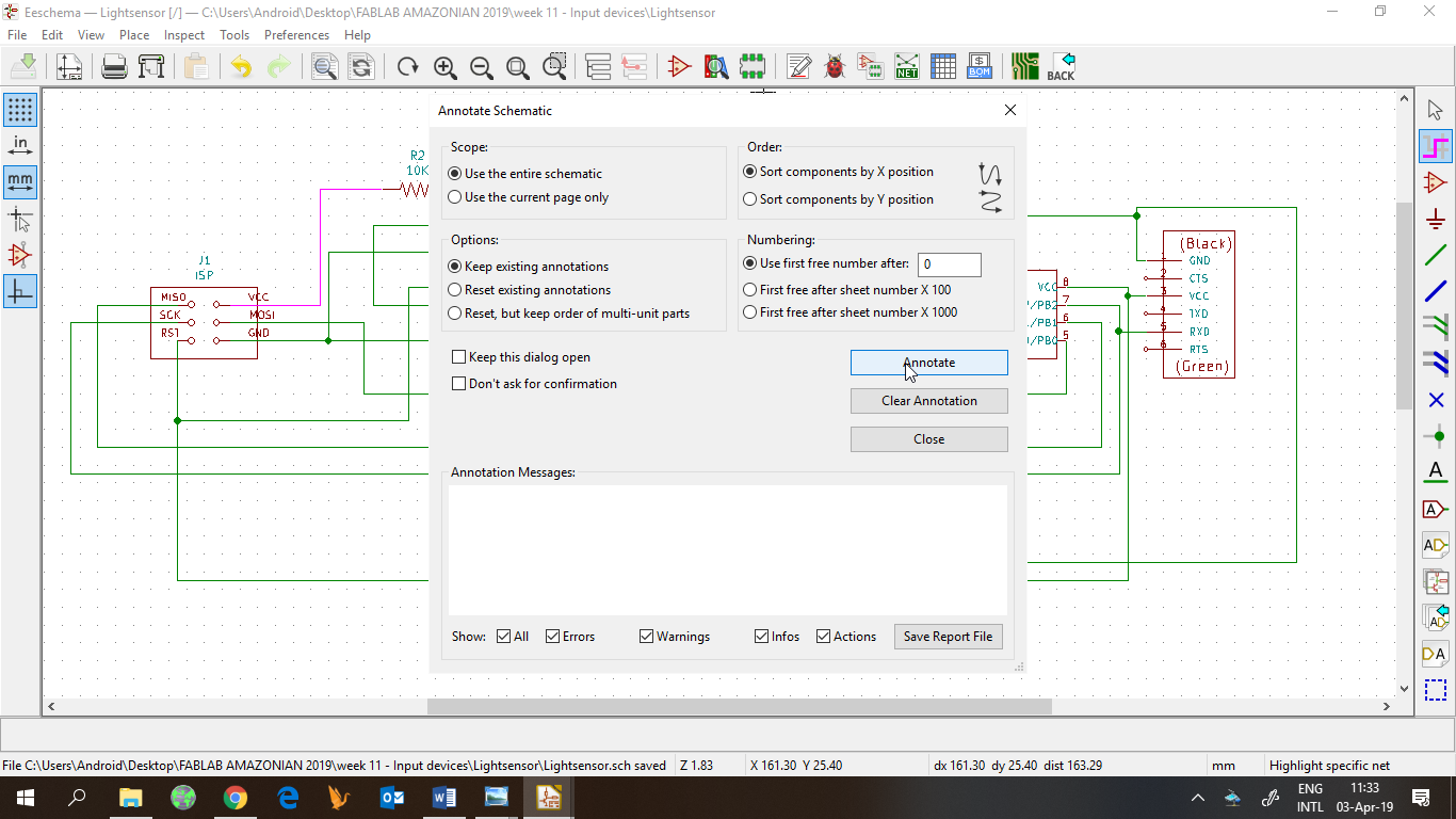
Then, the required process of annotating components,
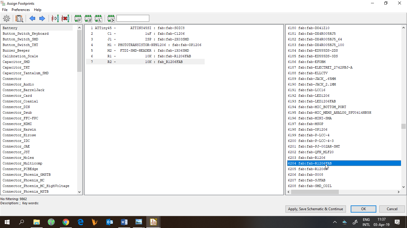
Assigning footprints,
And generating Netlist.
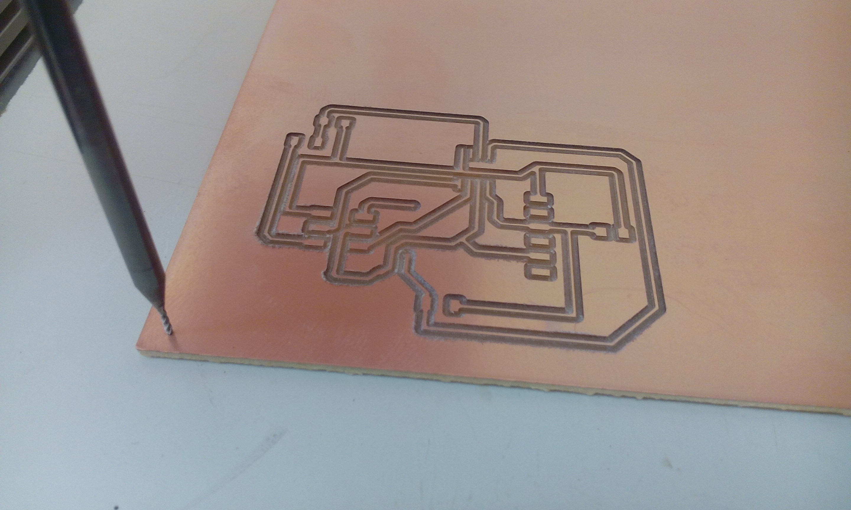
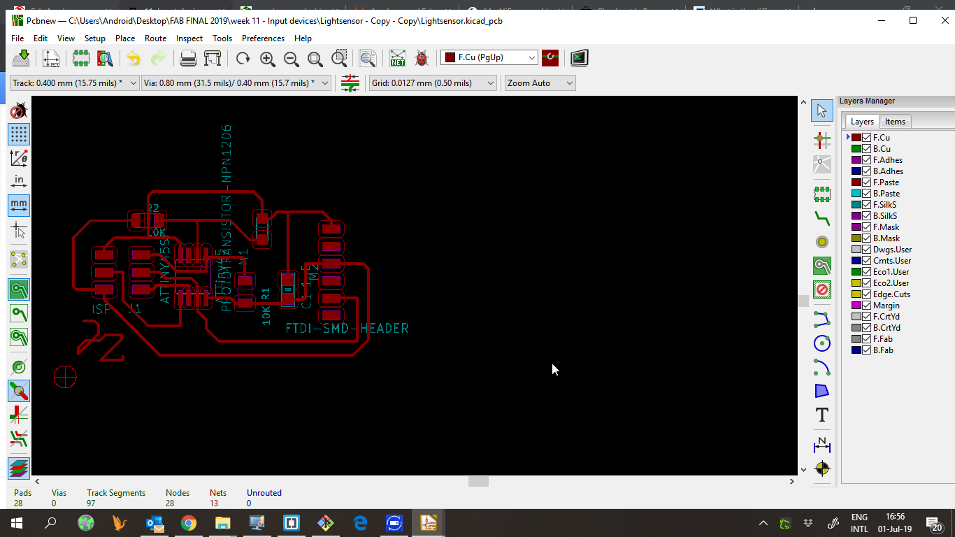
After that, go to Pcbnew to design the pcb. Because we were waiting for new 0,4 end mills, we needed to hack the design of the board this week. I left one track disconnected and will add a bridge to complete it.
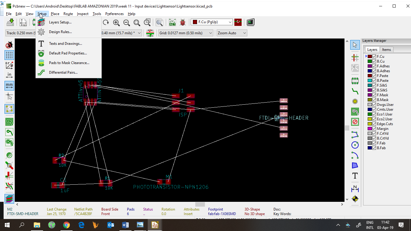
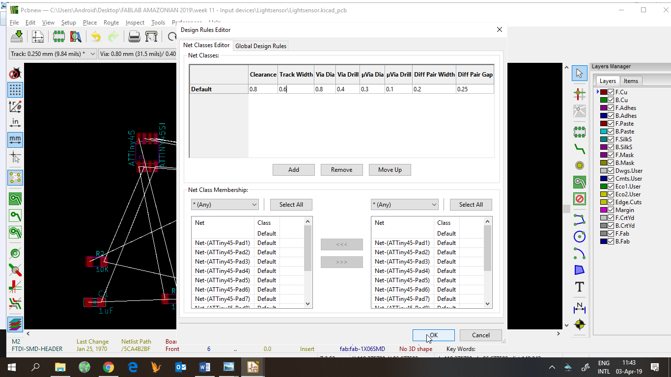
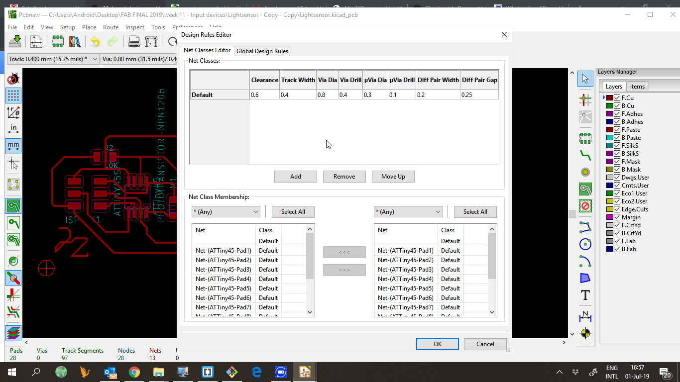
Since we were waiting for new 0,4 end mills, we changed the design rules to use a bigger end mill. I used the following design rules:
- Clearance: 0,8
- Track width: 0,6
And made the routes for the pcb.
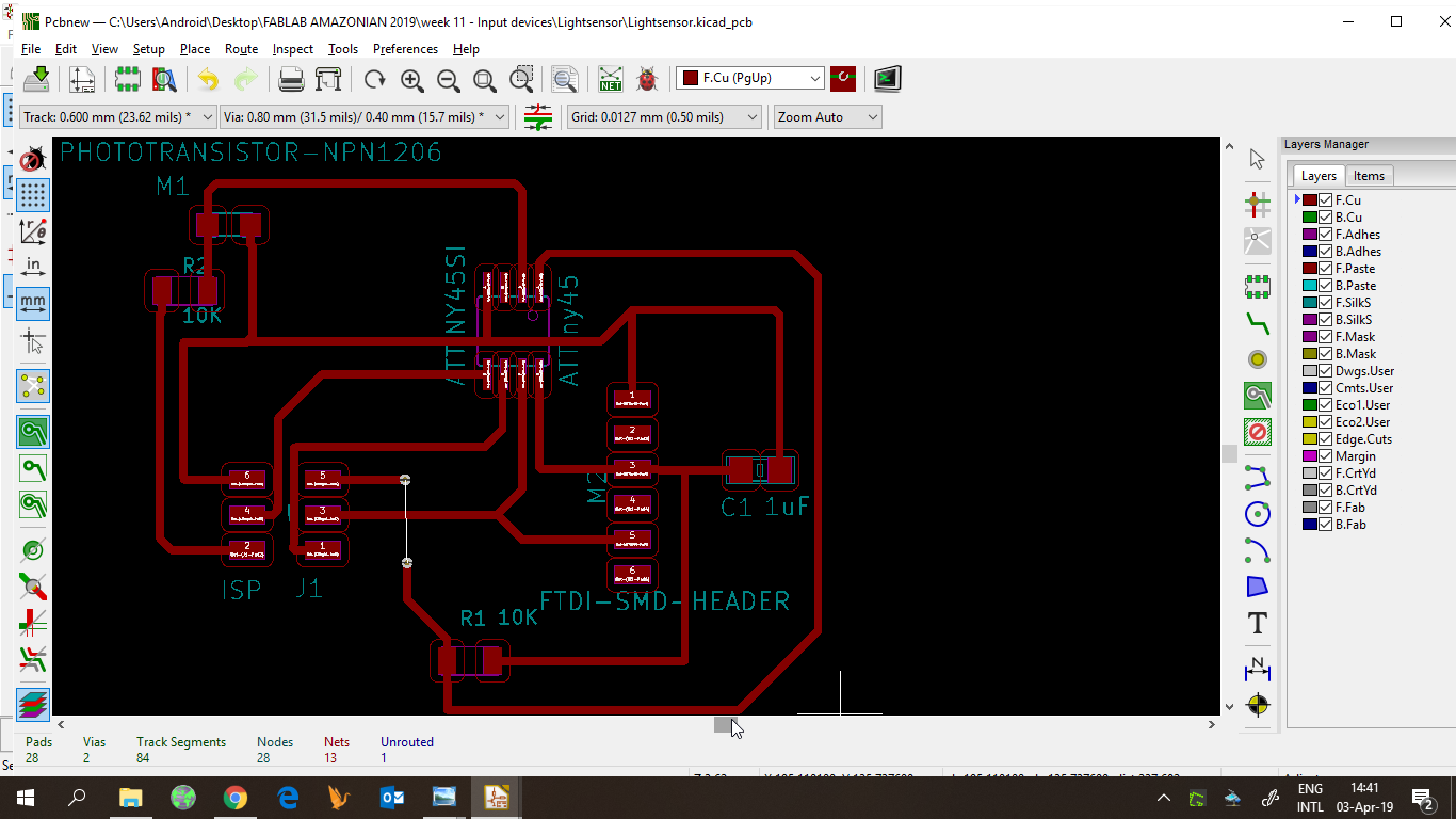
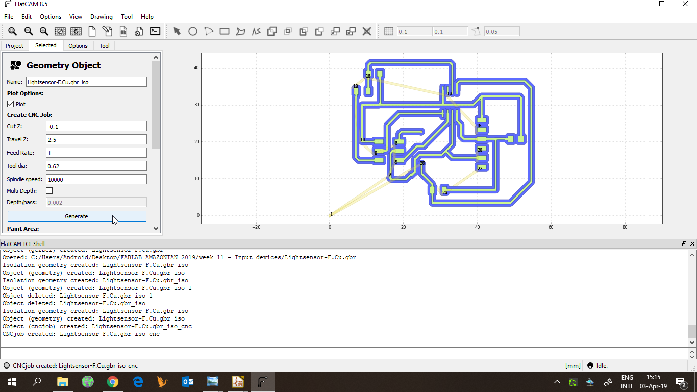
Then exported the board to gerber files.
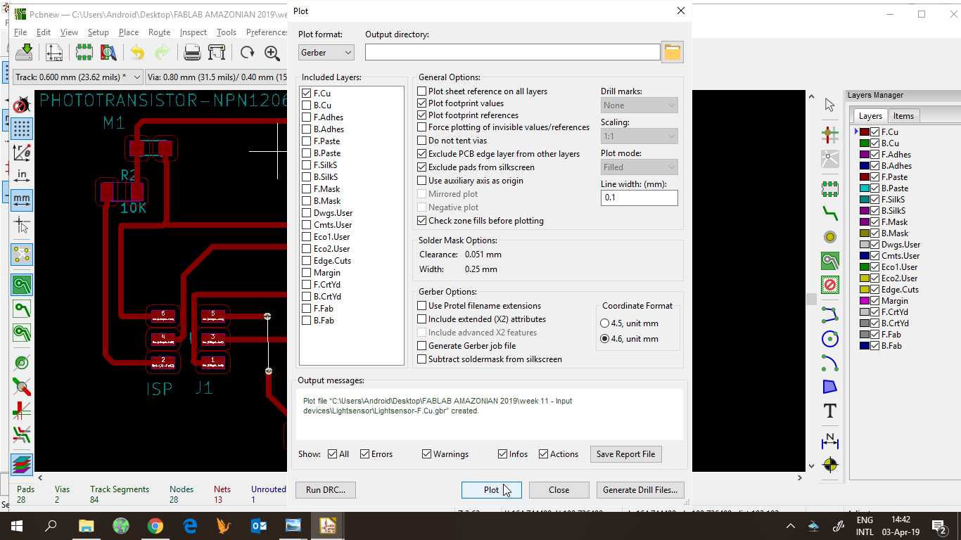
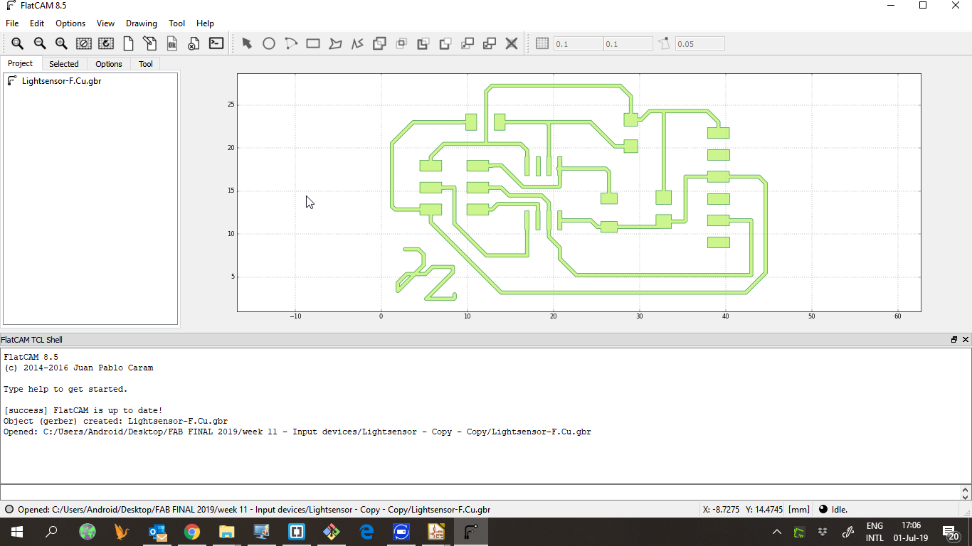
The gerber files are imported in Flatcam to create the gcode. The settings are:
- Tool dia: 0,62
- Cut z: -0,15
- Spindle: 10000
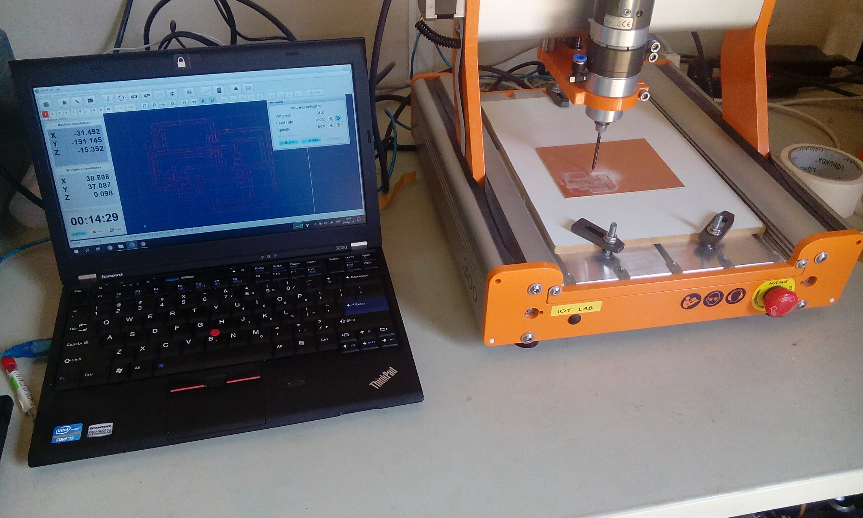
Cutting the board
With the toolpaths, I used Winpcnc and the Stepcraft milling machine to fabricate the board.
Solder & program
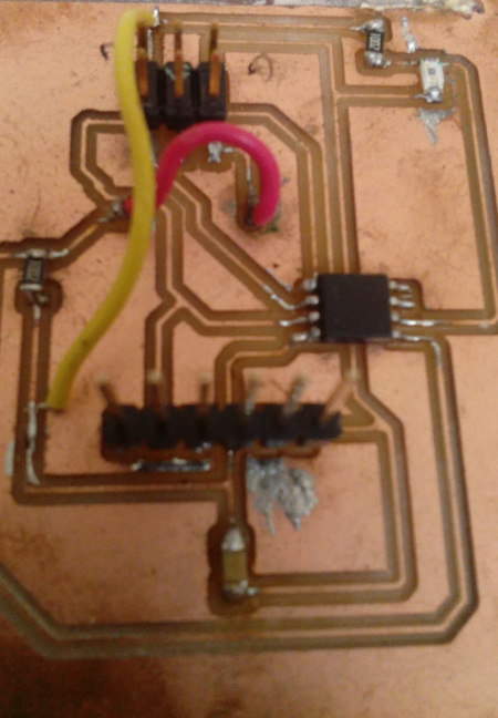
I added the bridge I needed, but realized I made a mistake, so I had to add another wire bridge to fix the board.
I used Neil’s code to test the board, and it worked fine
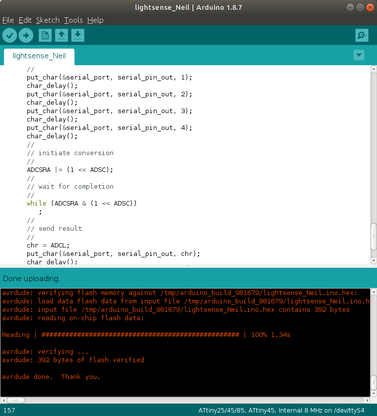
Then, I looked for some other examples and made a new code for my board. I hacked the code for a thermistor and was able to read my sensor.
I defined the sensor pin as pin 3 according to the attiny45 pinout for arduino, which is an analog pin.
I also used SoftwareSerial.h for the serial communication thorugh the ftdi connection, and defined the pin 2 as Rx.
The I read the value of pin 3
#define SENSORPIN 3
reading = analogRead(SENSORPIN); // read analog input pin 3
And finally print the value
Serial.println(reading);
I used arduino serial plotter to test my board.
Downloads
Redesigned board
Because as you can see the board had a bridge (The red wire, this was because we ran out of 0.4 mills)and another (yellow wire) because one VCC connection was not made i redesigned the board.
I went back to Kicad and changed the design rules, because i managed to get my CNC 3018 pro working, i could try to cut the board with the normal settings
I updated the PCB, and i saw also a mistake one VCC was not connected in the schematic so i corrected that right away.
The created Gbr file i loaded into Flatcam, and made the Gcode files (Nc) for cutting the board.
Thank you Enrico for the feedback!!!