Week 3
Computer aided Design

Scroll Down

Assignment


Assignment: Model (raster, vector, 2D, 3D, render, animate, simulate, ...) a possible final project, and post it on your class page
Learning outcomes: Evaluate and select 2D and 3D software, demonstrate and describe processes used in modelling with 2D and 3D software
Assessment: Have you:

  • a) Modelled experimental objects/part of a possible project in 2D and 3D software
  • b) Shown how you did it with words/images/screenshots, and
  • c)Included your original design files
  • Summary

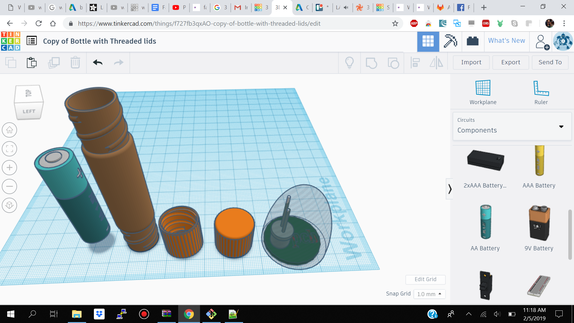
    • TinkerCad for 3d design version 1
    • TinkerCad for 3d design version 2
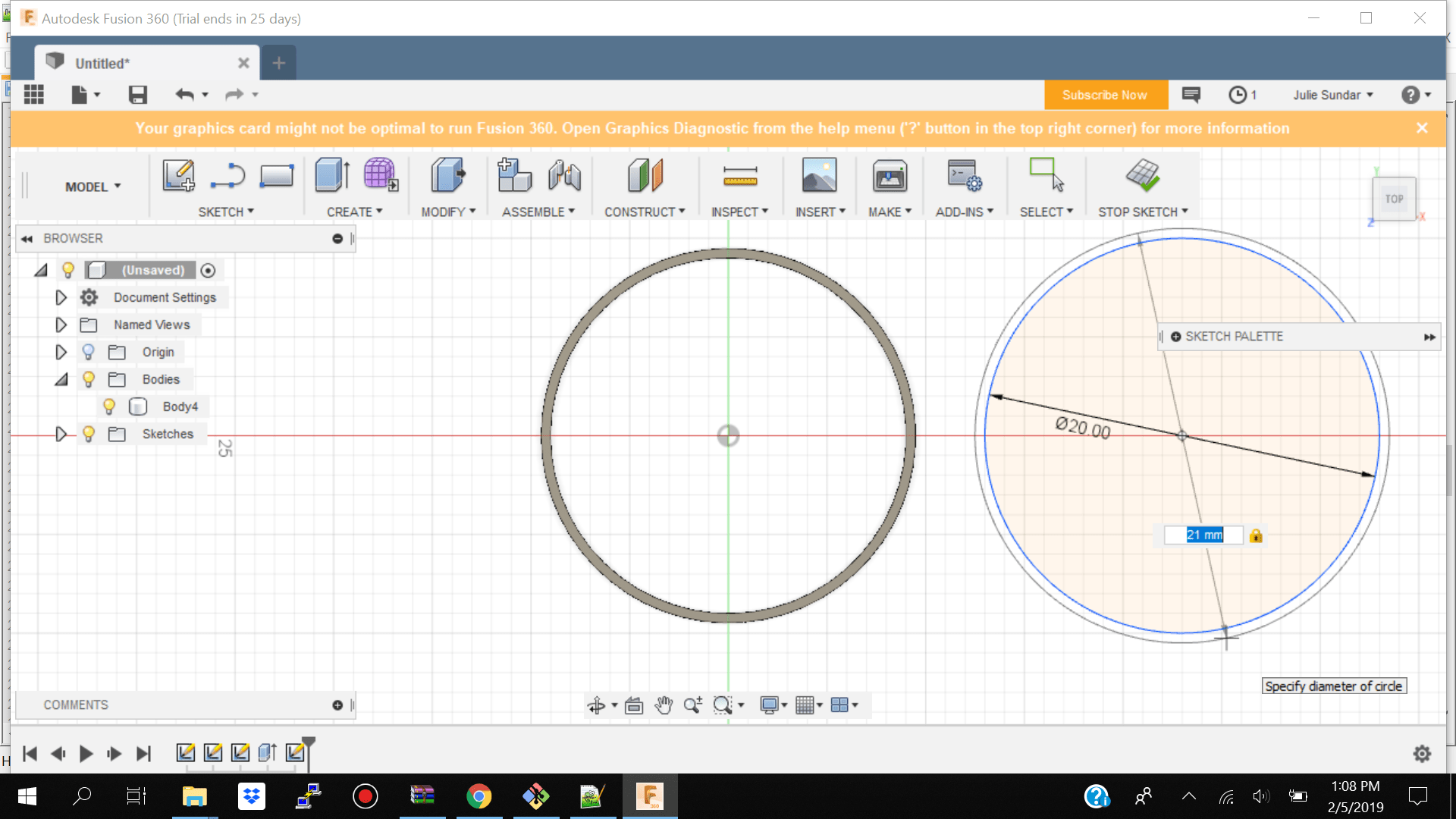
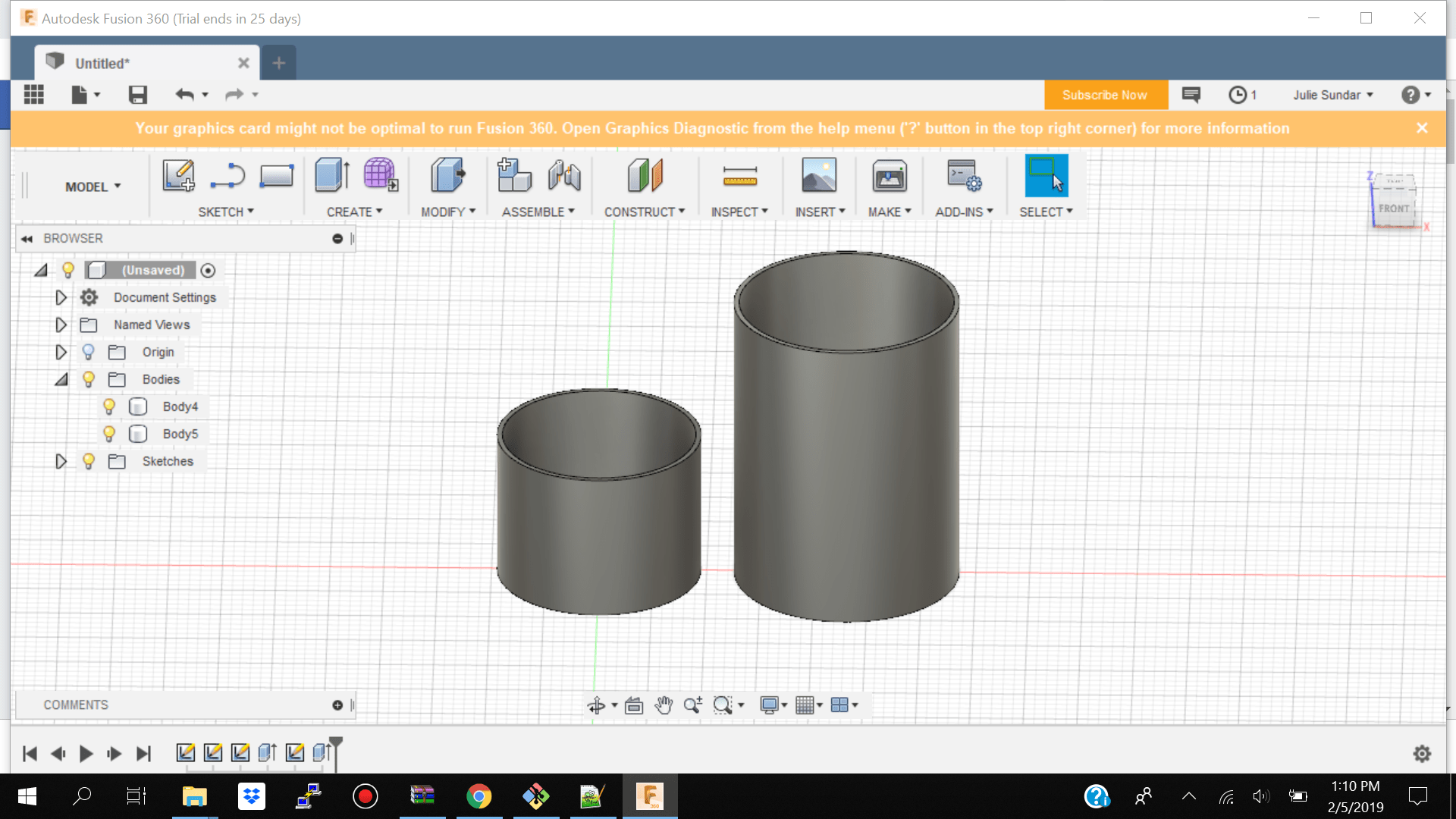
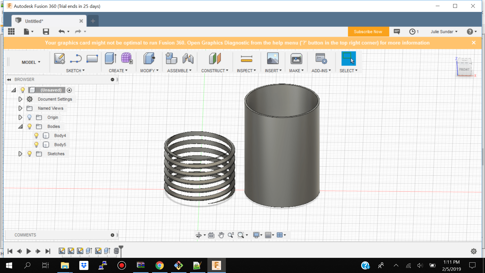
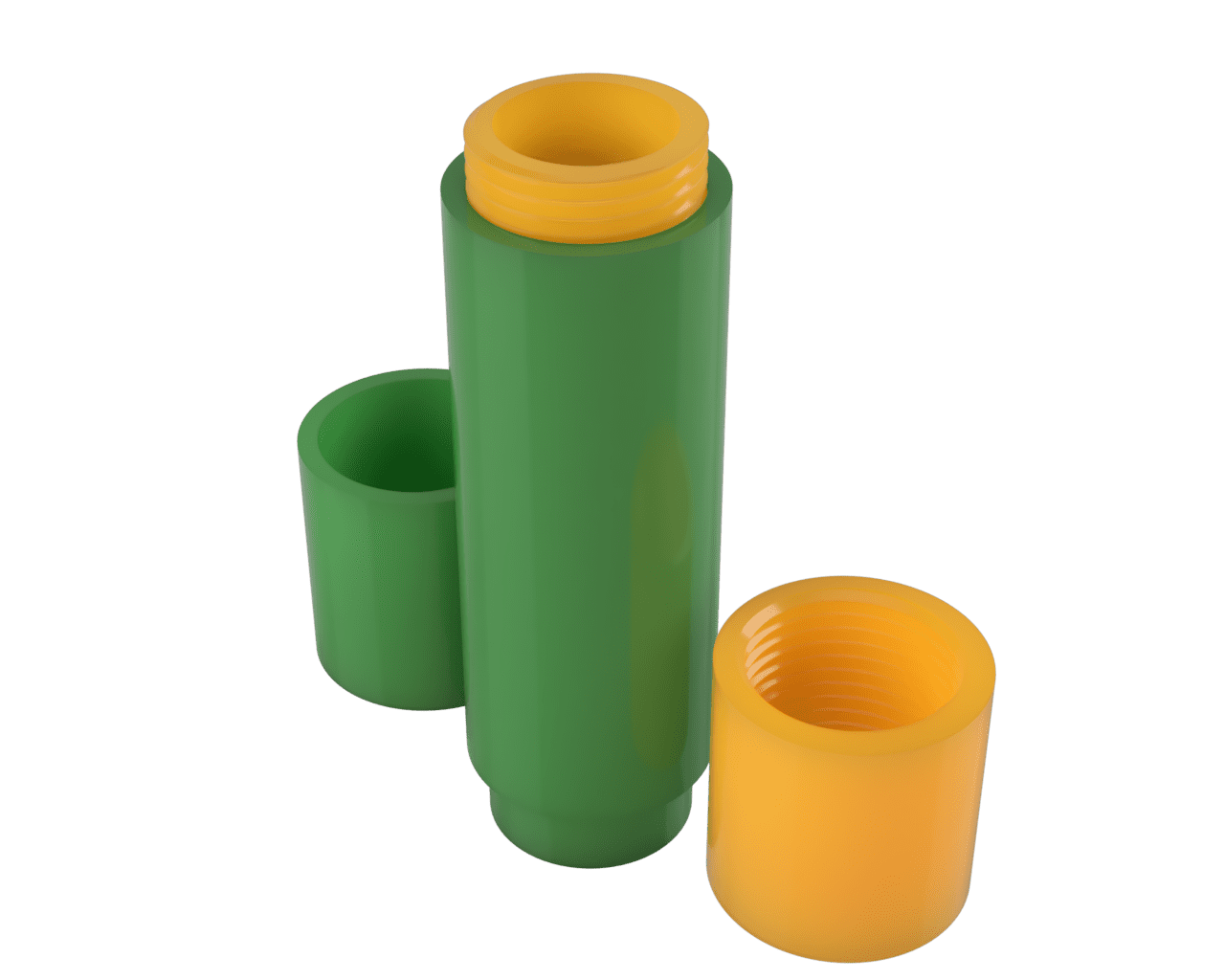
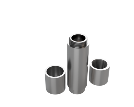
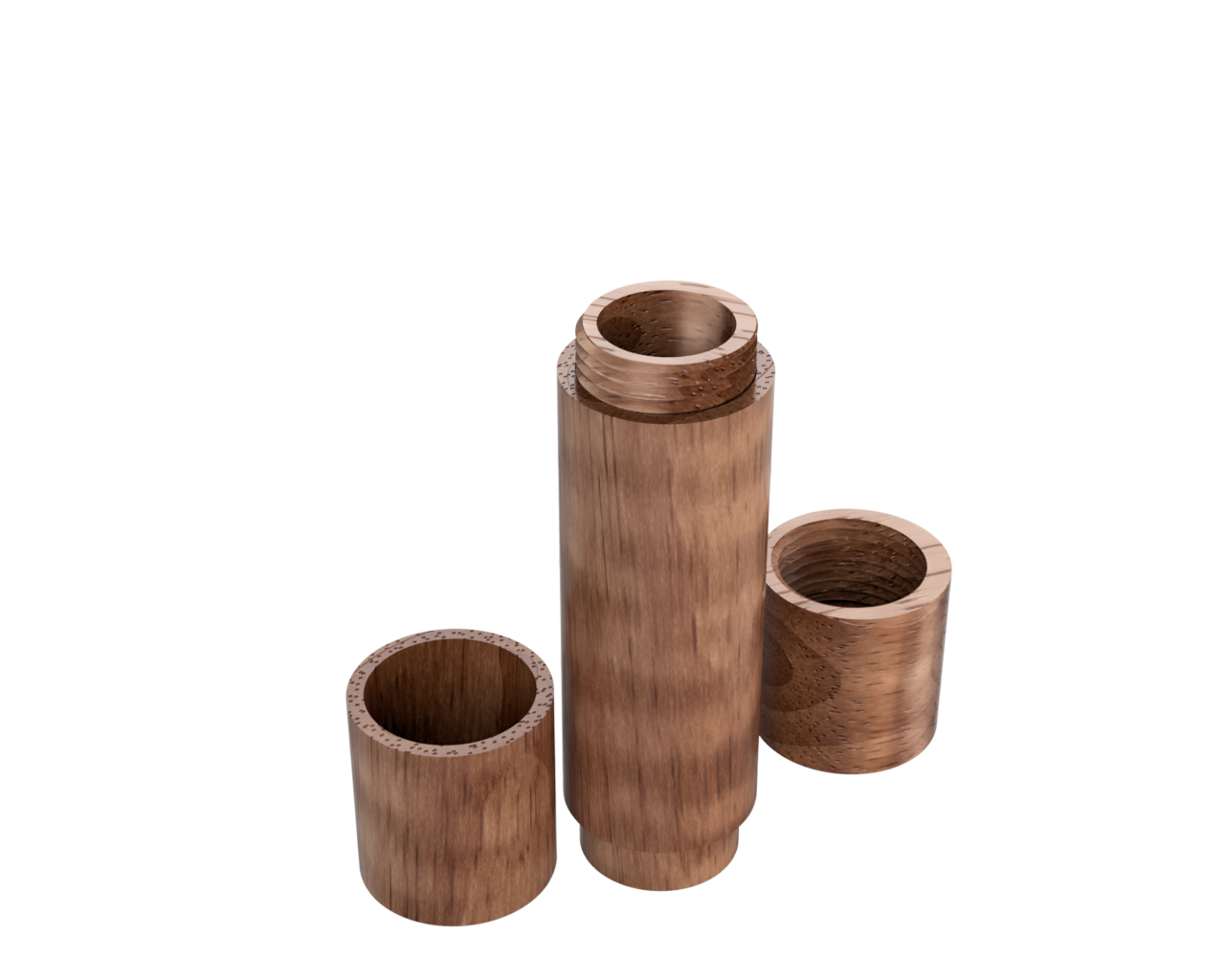
    • Fusion 360 to create 2d circles - extruded circles to create cylinders- made threads.
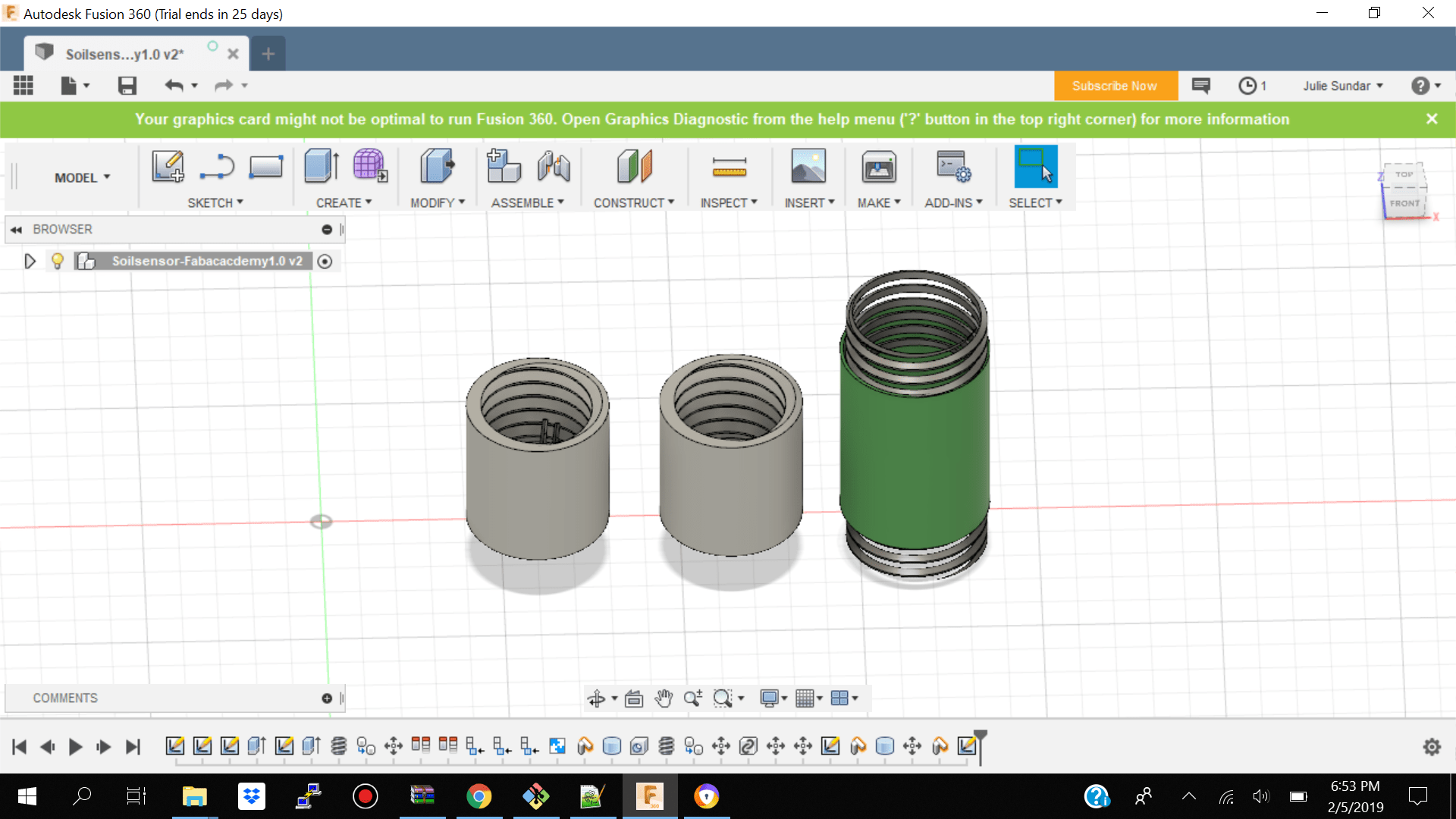
    • Fusion 360 to render textures onto my objects and 3d rotating video of my object
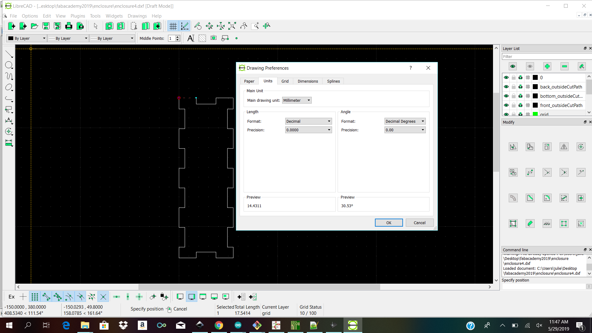
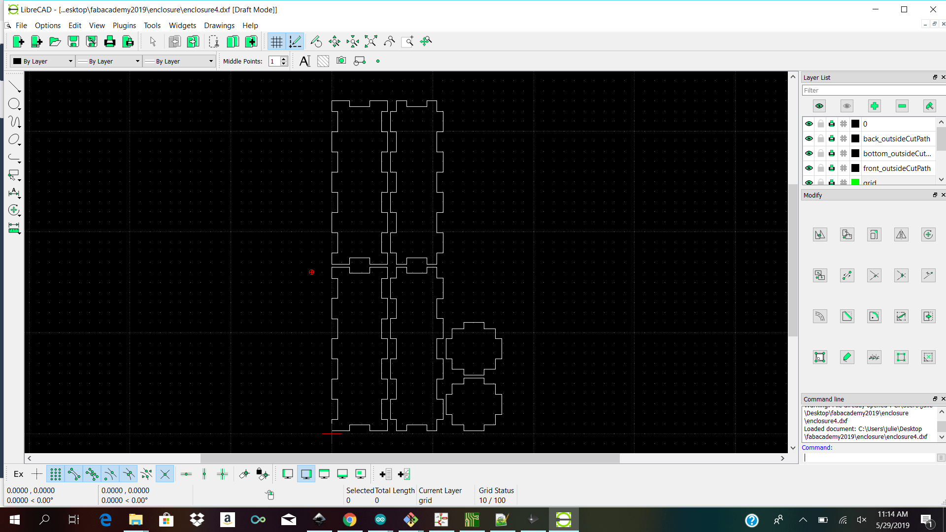
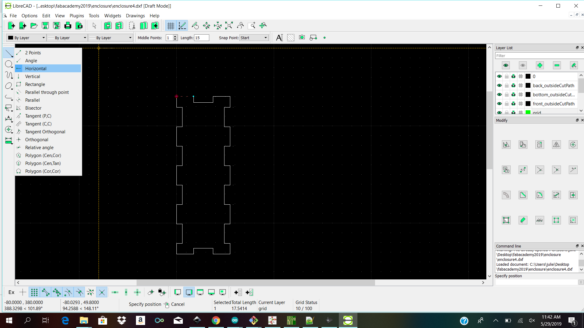
    • 2d design with Librecad for lazer cut enclosure
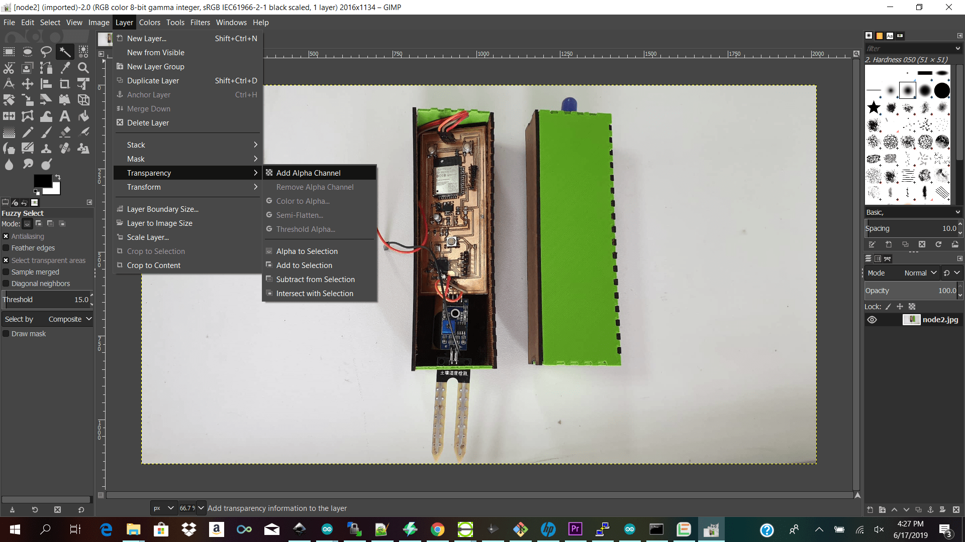
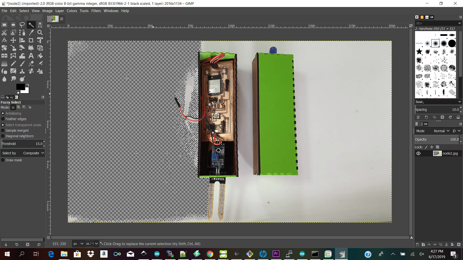
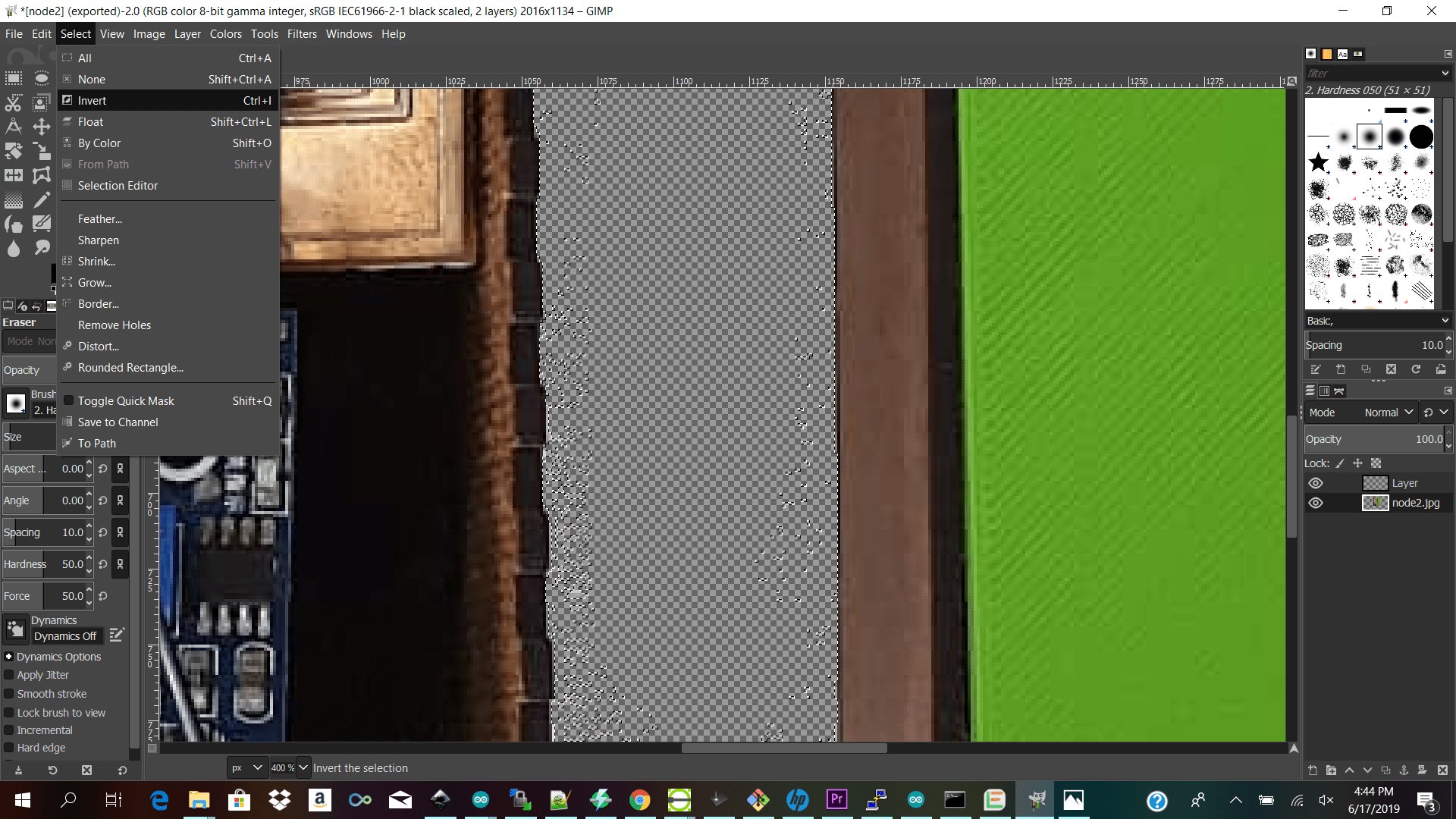
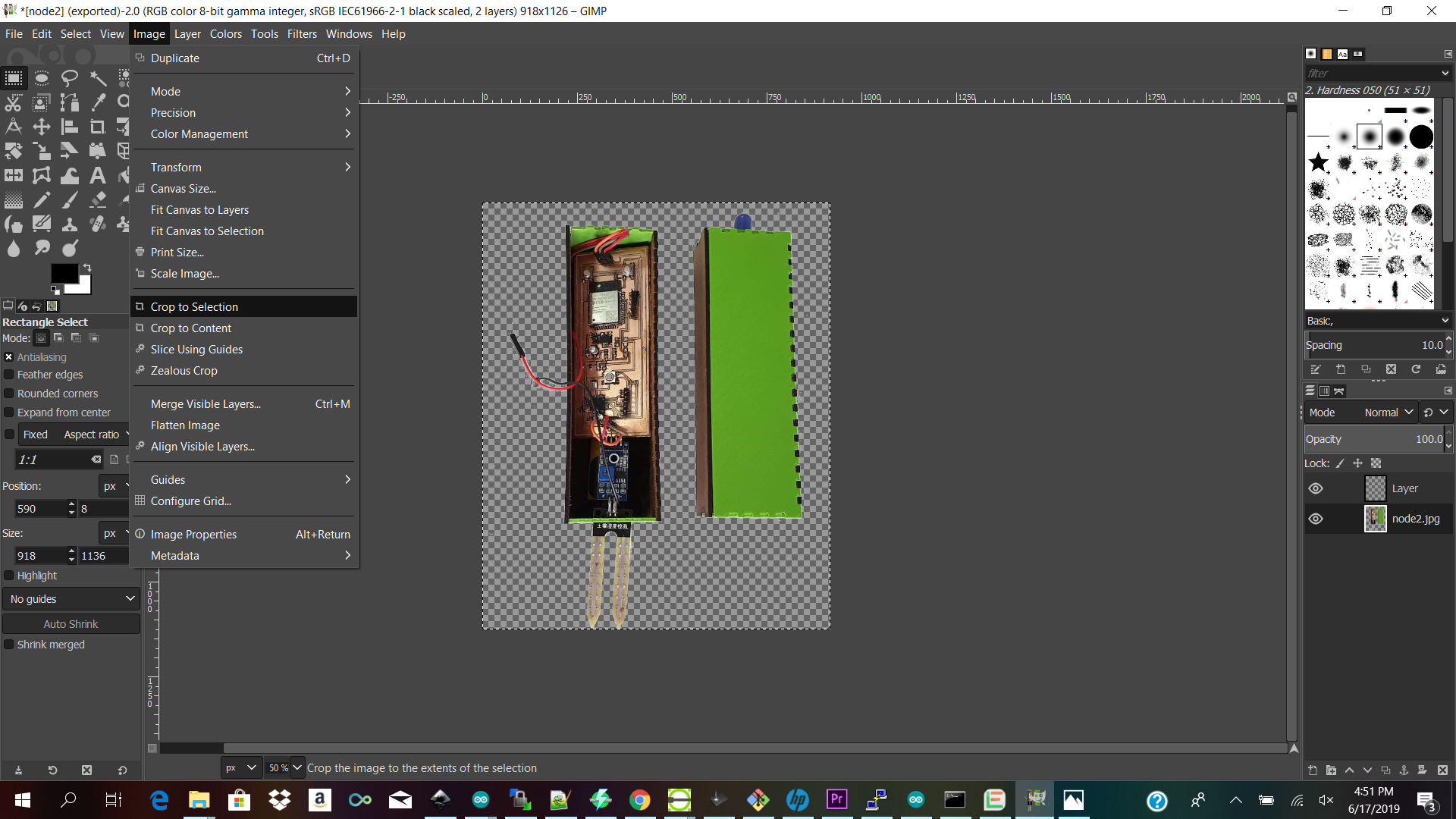
    • Gimp 2d raster software for removing background of images

    Redesigning

    Redesigning Version 1.0

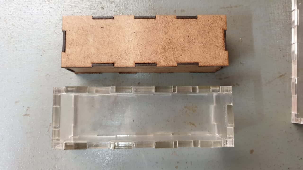
    Before I started 2d or 3d designing my final project I had to decide exactly what I would like to fit into my 3d enclosure and its dimensions

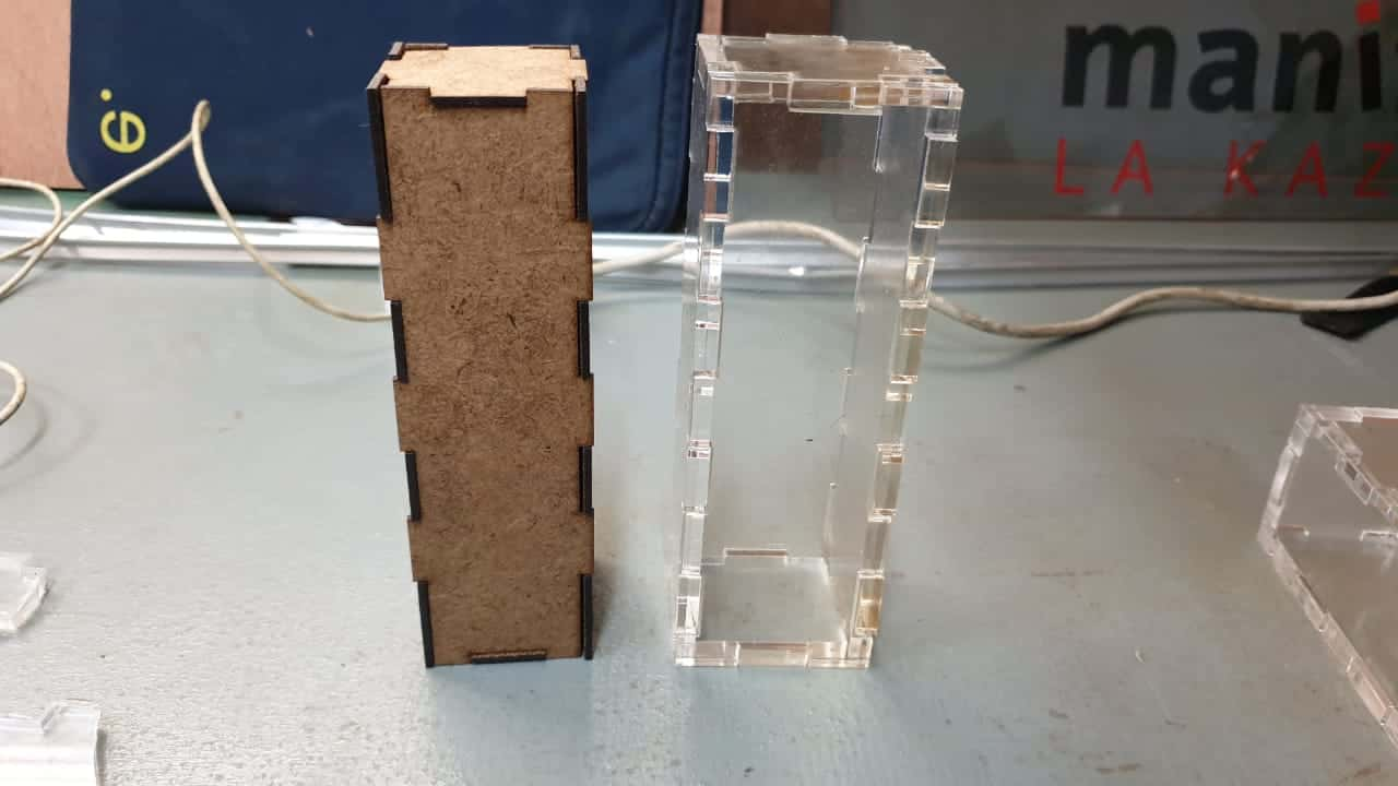
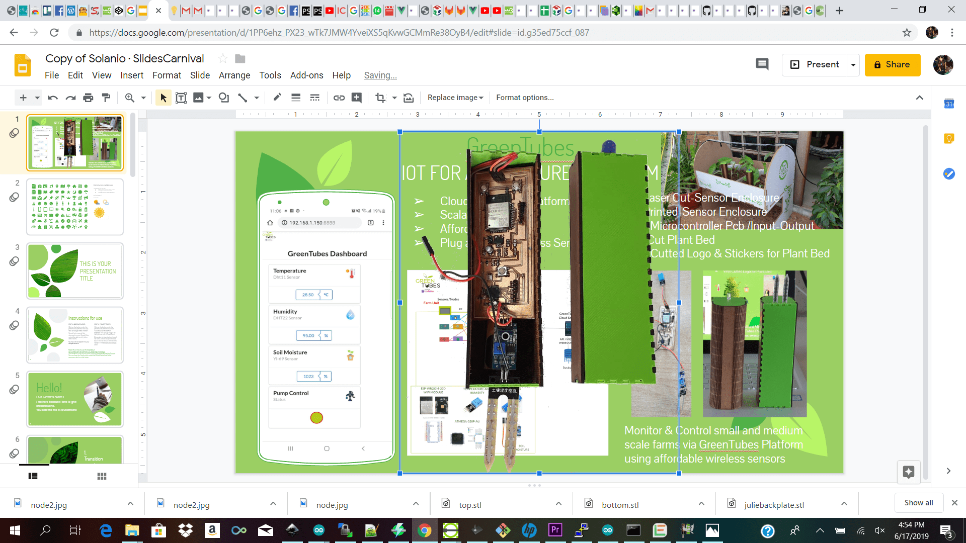
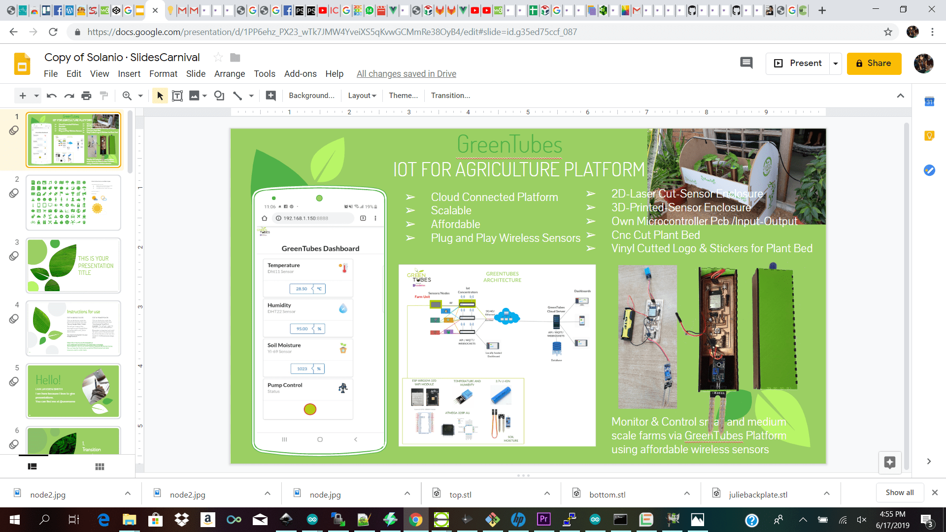
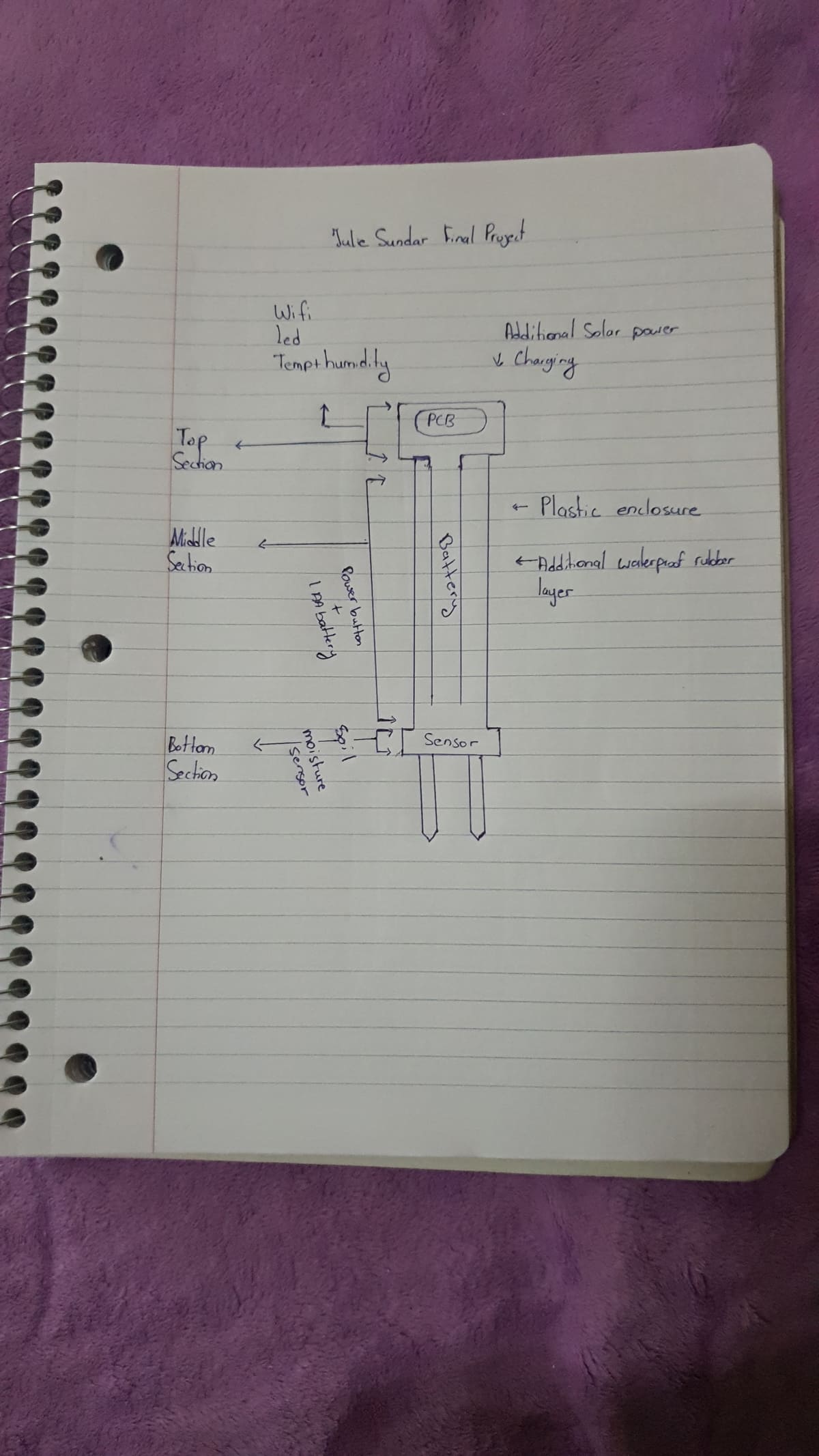
    I started off by redesigning what exactly I would want my sensor node to do. I wanted to design a rechargeable sensor unit containing three sections. The top section the base section and the bottom (screw on or plug on) sensor section.The top section would house my circular pcb with temp and humidity and led the (middle)base section would contain the battery and the screw on plug on section will have whatever additional sensor the user would like to add to their system for example my first proof of concept will be screwing on the soil moisture sensor.

    I want to design the sensor node this way because if a user would like to sense other measurements in the garden/farm they can just screw on and off their prefered sensor ex(ph nitrate etc sensors).I also want to design a way to add a mini solar panel to the node so that it can self charge when outdoors. I will start off by making just two sections the top and the base unit for my initial design to see how everything comes along before I go ahead and design the screw on sensor part because that will be the most challenging part for me to design.

    I then did some research on what components I would need to fit into my enclosure and I was looking for the most compact solutions.I knew I wanted my node to be able to connect to the internet over wifi so I had in mind to use the esp8266 wifi module on my custom pcb with 1 A0 analogue io for the soil moisture sensor and 1 DO digital io for the dth sensor.

    After doing some research I came across the GY-213V-HTU21D or SENSIRION SHT21 chip which was on the The HTU21D digital humidity and temperature sensor and decided to use that instead because it was smaller and I can just solder it to my custom pcb board all I needed was two lines for I2C communication. When it boils down to dimensions of my pcb board I will be covering quite a small space because all I will need is to have on my pcb is my power connector wifi module atmega chip and sht21 temp and humidity chip.For the additional design I will need to design my base enclosure to house my single Li-ion 2200mAh battery which is 69mm x 18mm.

    For the bottom section of my project the sensor screw on I will need to design the enclosure to just house my proof of concept the screw on soil moisture sensor.The only part of my design which I still need to fan out is how I am going to make the power trace to screw on a sensor with 3 traces instead of two. The power vcc an signal traces.

    2D Modeling/3D Modeling

    Getting started with CAD Softwares

    Today we were instructed to 2d or 3d model our final project with the use of a CAD software. As I do not have much experience using CAD software I decided to look for CAD software which were easy to use and for beginners. I tried blender, autocad, solid works but they were abit tedious to work with for the simple structure I wanted to model for my end project. I then continued to research and I came across tinkercad which was pretty simple to use and also color full which got my attention instantly. I was excited to get busy working with tinkercad because it was simple to use and it also exported to stl file format.

    After trying to design my final project (sensor node) with tinkercad for the first time I realized that it was limited.I do not have much experience with 3d designing but based on the shapes that were avalible on tinkercad no matter how many times I tried to model my project the end result did not look like I imagined. I decided to do some more research and try out yet another 3D modeling Software.

    Tinker Cad Trial 1

    Tinker Cad Trial 2

    After trying tinkercad for the second time I realized that I was able to do abit more because I was abit more fimiliar with the environment.Since my final project enclosure was not that complex I was able to make most of the base using tinkercad.I was able to make the middle section with the double side threads and the screw on caps. The issues which I encountered because tinkercad is limited to specific shapes was scaling my screw on caps from a small diameter to a larger diameter to fit my pcb and led. I then decied to try out fusion 360 to see what it.

    Tinker Cad Trial 2

    Fusion 360

    The next tool which I decided to use was Autodesk Fusion 360. I decided to use Fusion because it seemed to have more option that tinkercad but also seems reasonably easy to use. Starting Fusion displays a new project in the Model workspace.The toolbar is located at the top of the window along with menus that give you access to a wide range of additional commands.

    The menus arrange the tools for working with 2D and 3D drawing in groups and also includes options for assembly,constructions,and CAM processing.

    I started off by sketching my 2d parts like the dimentions of the circles for my enclosure and extruding them into a cylinder.I then went ahead a looked at a few youtube videos on how to make threads in fusion 360 and overlay my first cylinder with the tread and select modeled to make sure it will be viable to print or lazer cut when I export to stl file format.

    I then created two more cylinders with the same dimentions circle inside to get a hollow center and I added my thread to get the top and bottom caps.What I still need to do is finding out how to go from small diameter to a bigger diameter to get more space in my cap to hold my sensors.

    Fusion 360 Trial 1

    The first thing which I did was to estimate the dimentions of my inner circles which were first 18mm for the hole and 19 mm to be extruded and 20mm for the second inner hole and 21 to be extruded via

  • Sketch --> Circle --> Circle Diameter Circle.
  • To extrude my circle I selected which circle I would like to extrude and selected

  • Create--> Extrude.
  • I then wanted my first extruded cylinder to become my thread so I then selected

  • Create -- Thread
  • and selected my cylinder which I would like to turn into a thread make sure to check off the modeled check box in the thread menu box so that when you are going to print your thread all the points are made.

    I then duplicated my threads to fit on top and bottom of my base cylinder and created two more cylinders for my caps. I then added a threads inside my caps by clicking

  • Create -- Thread
  • and selecting inside the cap where I would like the thread to be placed note:When creating your initial thread the parameters will be saved in fusion so when creating the second thread for the cap the parameters will match.

    Fusion 360 Trial 2

    2D Design Using Librcad

    For 2d designing I used Librecad to make a design for my final project enclosure if I do not get enough time to make my enclosure circular due to time limitation with the 3d printer. I would use this design to lazer cut my enclosure.

    When using Librecad I used horizontal and vertical menu items for making my design and I add my length in the length parameter above. To choose my metric unit I had to go to

  • options
  • current drawing options
  • units - millimeter
  • Width 43 mm
  • Height 150mm
  • Depth 40mm
  • note: I lazer cut my design in week 17

    Gimp 2D Raster Software

    I downloaded Gimp 2.10.10 for Windows 10 and learned how to remove background of my images to add to my presentation slides sadly I learnt this after the final presentation xD but I will be using this for all my slides!

    I imported my imaged into Gimp

  • File -> Open as Layers.
  • I then click on the background which I wanted to make transparent

  • Layer -> Transparency -> Add Alpha Channel
  • I started to make the rought deleting of the background by selecting and deleting

    I then selected the image and clicked invert to better see the left over stuff outlined and used the earser tool to clean it up

  • Select -> Invert
  • Eraser Tool
  • I then used the wanted to crop my image so I used the Rectangle Select tool selected my parameter I wanted to crop and did image crop to selection

  • Rectangle Tool
  • Image -> Crop to Selection
  • I then exported my image as png and imported it into my slide it looked great!

    Download Files Here

    Fusion 360 stl
    Tinkercad stl Librecad Design

    Contact Us

    Where To Find Us

    Paramaribo Suriname
    Ethnalaan
    50..

    Follow Us