Week 5
Electronics production

Scroll Down

Assignment


Assignment: Group: Characterize the specifications of your PCB production process. Individual: Make an in-circuit programmer by milling the PCB (program it, so that you can use it to program your board in Electronics Design week, and in other weeks). Optionally, trying other processes.
Learning outcomes: Describe the process of milling, stuffing, de-bugging and programming. Demonstrate correct workflows and identify areas for improvement if required
Assessment: Have you

  • a)Shown how you made and programmed the board,
  • b) Explained any problems and how you fixed them,
  • c) Included a picture of your board
  • Group work

    We have linked our group assignment external you can view it here

    Characterize the design rules for your PCB production process

    Features


    Integrated modular control electronics for an easy connection to the computer via USB or parallel interface
    Stepper motors from Nanotec®
    4-track roller guidance
    8-point ball bearing carriage on all axes / linear profiles
    In-house development of STEPCRAFT aluminum profiles
    Standard Ø 43 mm tool holder enables the use of third-party devices (if necessary with adapter)
    Integrated workpiece clamping system (clamping bridges) for plate materials with a thickness of up to 15 mm
    Connection elements out of stainless steel or aluminum
    Easy, infinitely adjustable guide play without disassembly
    High-precision lead screws from Switzerland with spindle nuts out of bearing bronze
    Inspection cover on the Y-axes with silicone sealing for dirt protection
    Machine table made out of wear-resistant HPL
    Quick-change system for the exchange of the machine table
    Easy-care and wear-resistant surfaces (powder coating, anodizing)
    Compact size
    Made in Germany
    Overall Size (X,Y,Z): 350 x 430 x 410 mm
    Working Space (X,Y,Z): 210 x 300 x 80 mm
    Clamping Surface (X,Y): 222 x 380 mm

    Software

    WinPC-NC or UCCNC.

    Required Tools


    Slotted screwdriver 3 mm
    Allen wrench 1,5, 2,0, 2,5, 3,0, 4,0 and 5,0 mm
    Spanner 7 mm and 8 mm
    Long-nose pliers
    Slide gauge
    Cutting knife

    System Requirements


    PC with 1 GHz processor
    USB-interface
    Windows XP oder hoher (32/64 bit)
    MAC OS X 10.3.9 or higher with Windows® emulation

    Summary

    • Install Winpcnc software for Stepcarft C300
    • Bitract our png images using Inkscape
    • Export the file to dfx
    • Import the file into FlatCam and add parameters and generate gerber object
      Cutz -0.2
      Travel Z -2
      Feed Rate 3.0
      Tool Dia 0.2
      Spindle Speed 1000
    • Generate gerber object to gcode
    • Import into Winpcnc ready for the Stepcraft to use it.
      Set origin to zero
      File formatt -invert z axis
      Jog x y z position and start cutting
    • Solder Components
    • Flash and program the fab isp using ubuntu

    Milling the Pcb

    Milling the Pcb

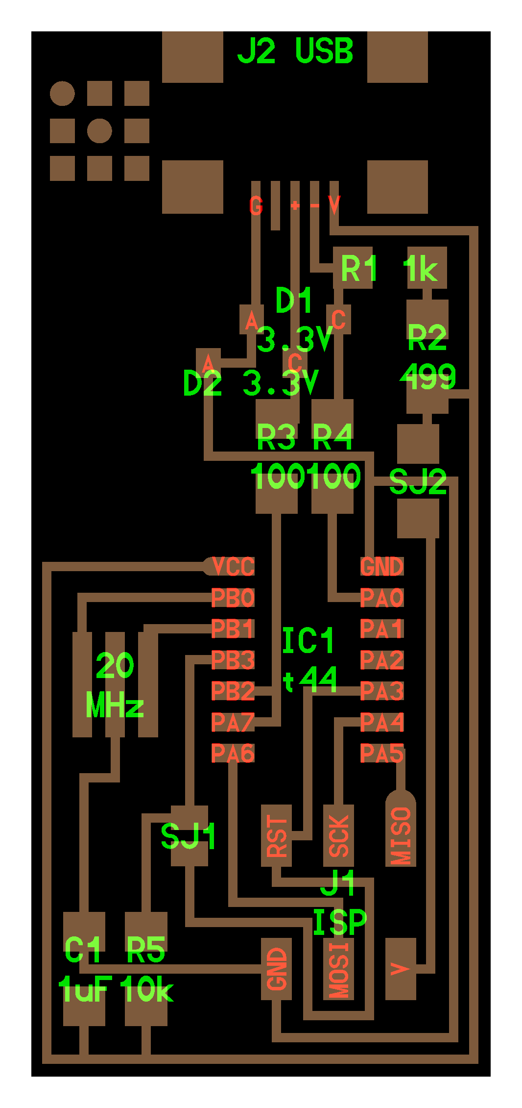
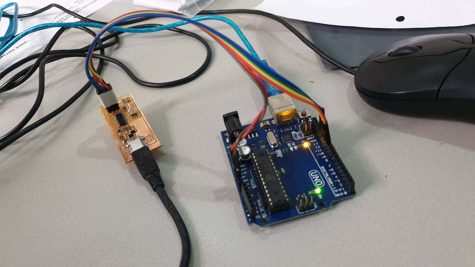
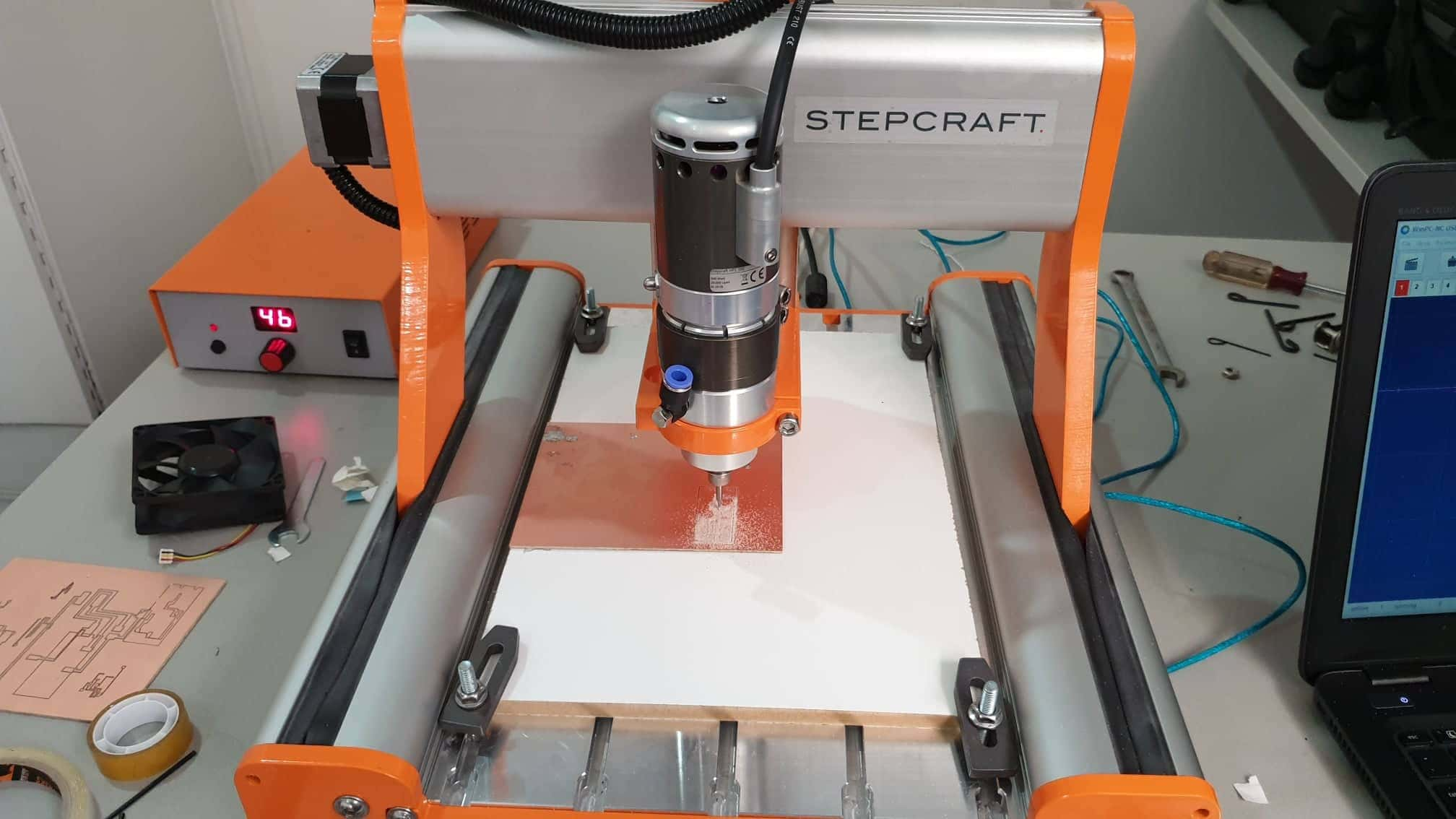
    This week we were assembling our own in circuit programmer that we will be using later on in the course. The first thing we had to do, was to select what kind of Printed circuit board (PCB, in Finnish Piirilevy) we wanted to do. In this weeks FabAcademy site we were given some examples on how to carry it out using either ATtiny44 or ATtiny45 microcontrollers. hello.ISP.44.res.cad board traces interior

    The machine which we were using was the stepcraft c300 for making our outline for our pcb.

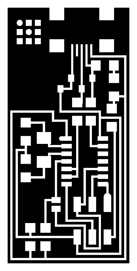
    1. The first thing I did, was to download the traces file, and the outline file as image files (png) to my computer.

    The traces file is basically the layout of your PCB, and the outline file is the outer part of your pcb both will then be used to cut out your PCB.

    The tools which we used were Flatcam 8.9.0 and inkscape

    and we also had to install the Winpcnc software to work with our stepcraft machine.

    I then went ahead and imported my trace file and outline file of the pcb into inkscape and bitrace it. I then saved them as a dxf file onto my computer.

    I then went ahead and imported my trace file into Flatcam as dfx and on initial import I had to change the base parameter from px to mm. I then went ahead and change my selected object parameters
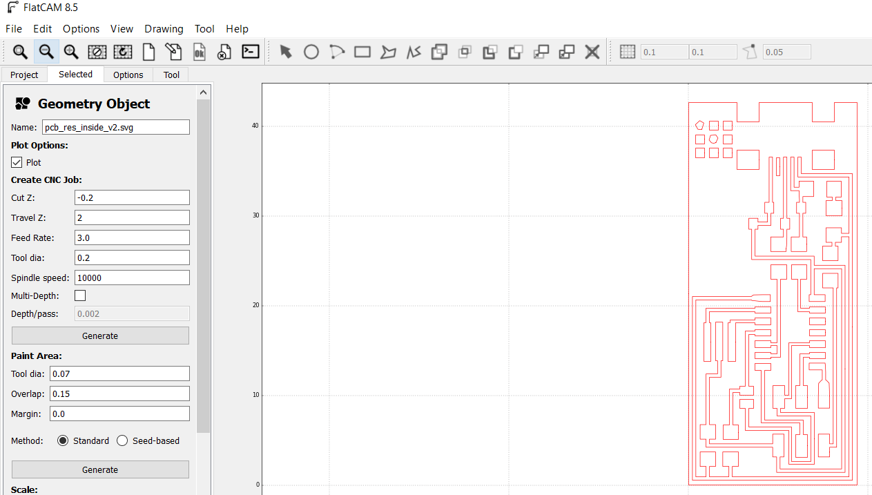
    Flatcam Selected
    Tool Dia 0.2
    Cutz -0.2
    travel Z 2
    Feed-Rate-X-Y 3.0
    Feed Rate Z Plunge 0.5
    Spindle Speed 10000

    note: Set origin to origin of coordinates

    Uncheck the option about ignoring gcode parameters

    Then I went and generated my file pcb.dfx_cnc file and saved it onto my computer.

    I then went ahead and open Winpcnc and imported my cnc file.On initializing you need to select your language and which machine you need the parameter for in my case was stepcraft c-2/300.

    I then went ahead and double check my parameters from the parameter menu item and double checked.

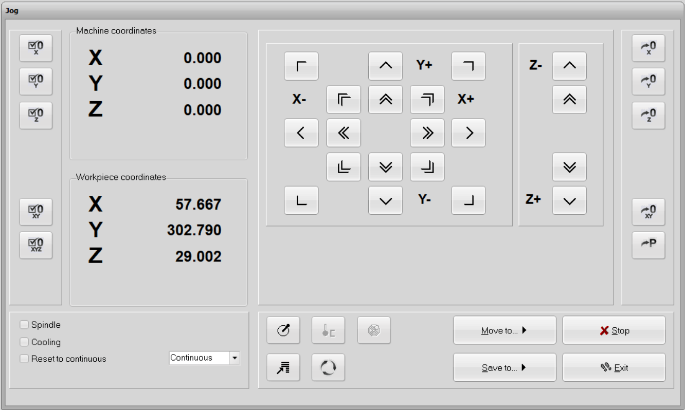
    Most of the parameters have been setup into flatcam. I only had to tick the "invert Z coordinates" option into Import Formats options. Before launching the machine I had to setup the zero. Into move>jog, we can manually move the machine to our desired zero point. We used a sheet of paper between the mill and the PCB to have a precise Z-zero. When X, Y and Z are to my desired point I just click the 0-XYZ button as shown on the picture below and the machine goes to a safe position 10 millimeters higher.

    Then I went to parameters tools and make sure the spindle speed was correct I choose 1000 and in the speeds tab I changed the V-Plunged and V-Advanced parameters. And double checked the Dimensions Tab.I also changed on the import format tab to Invert-Z coordinates.

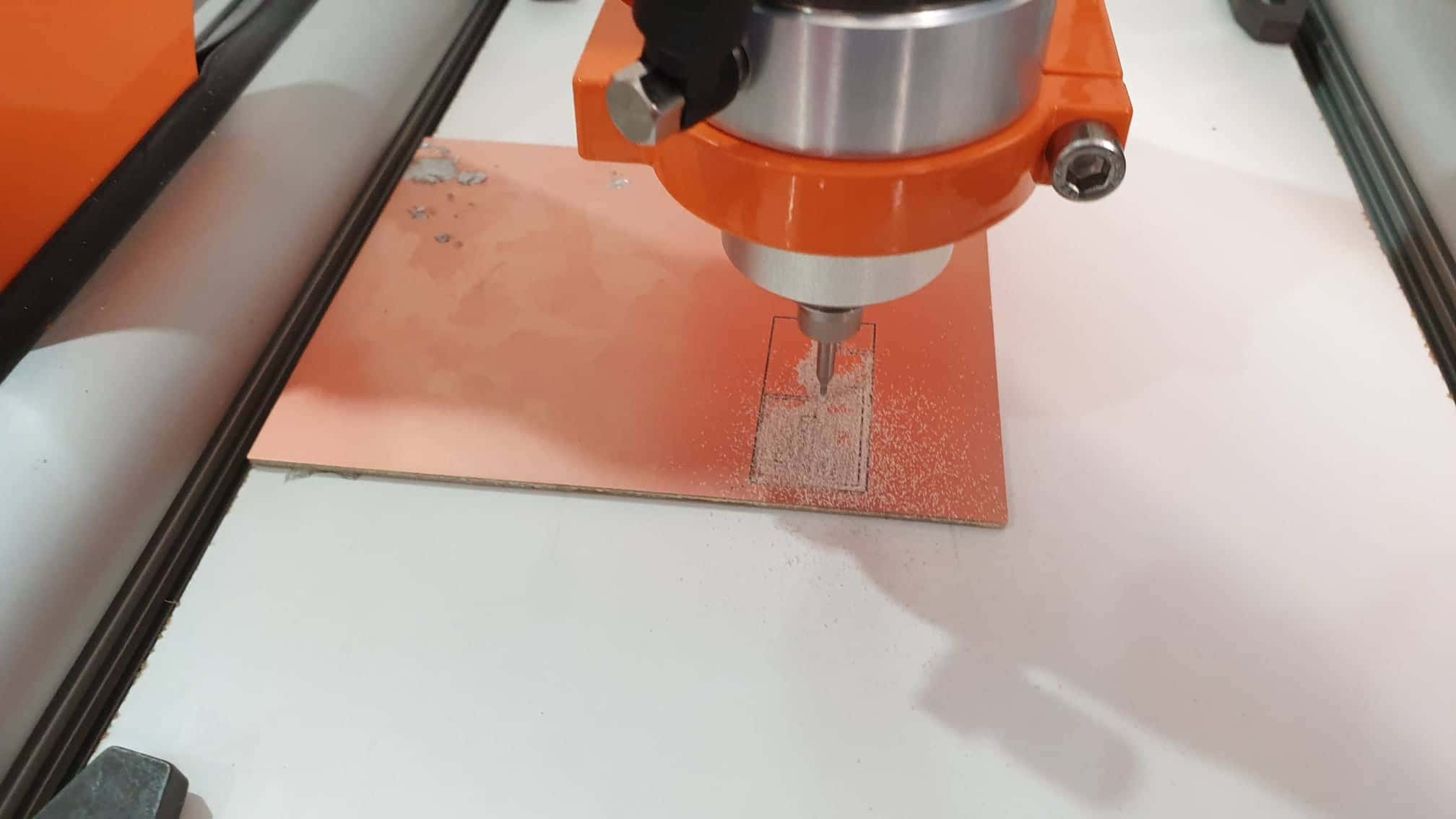
    After double checking I then clicked on move and start.

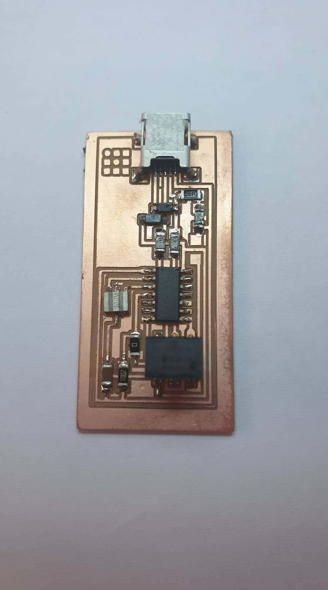
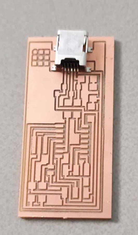
    After the traces were finished I then went ahead and did the same thing for the outline file so that it can outline around my pcb with the same initial parameters.

    Lessons


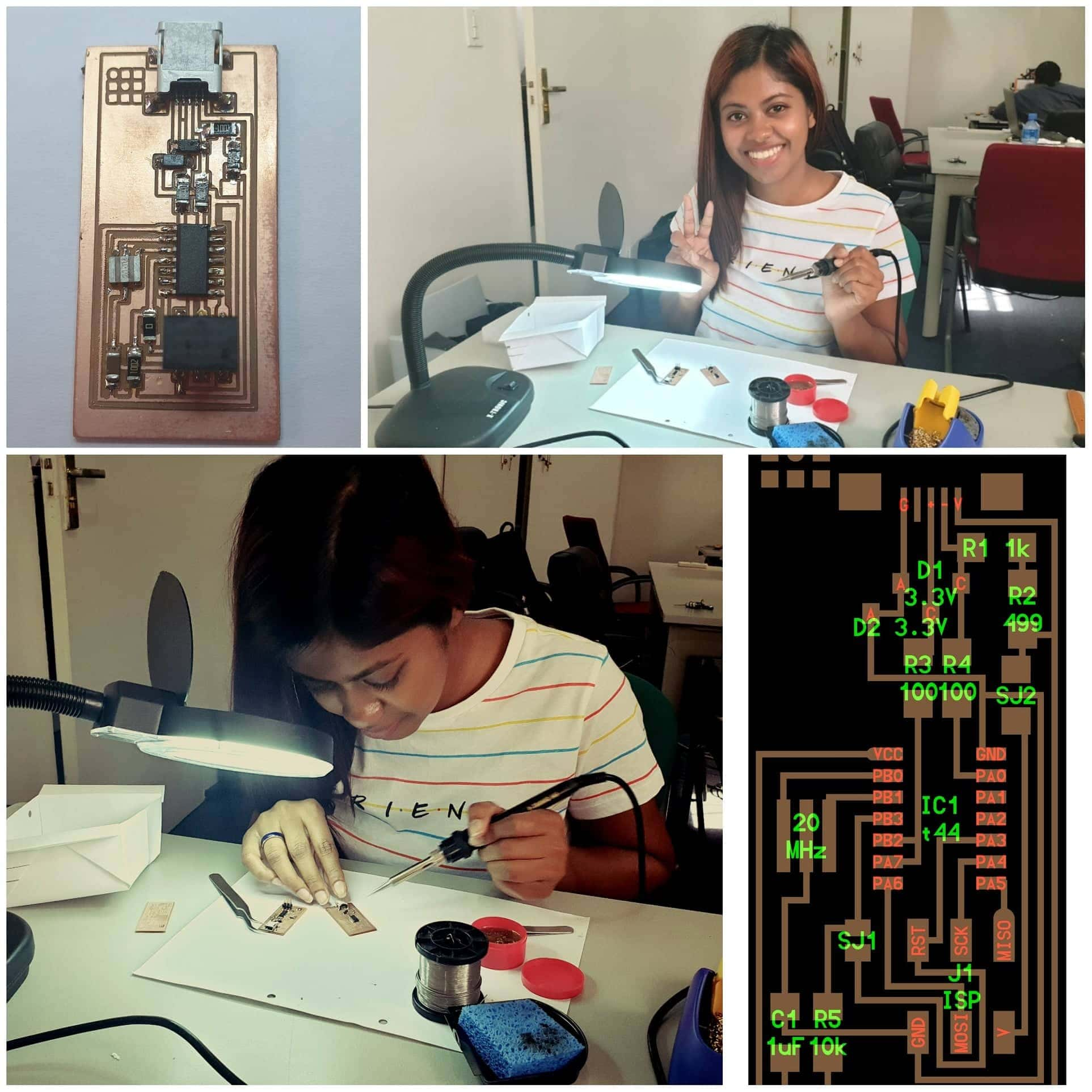
    I learn alot this week working with the cnc machine. Starting with helping assembling the stepcraft c300. It took us 10 hours to put the step craft together and getting it to work.The machine looks small but it takes time to assemble it and callibrate it correctly.
    Working with the stepcraft took up alot of our time because when trying to install the software (winpcnc) to work with the stepcraft we initially could not get it to work. The software was crashing on our windows os. Another issue which we were having after that was scaling and getting the correct measurements for the the traces and outline images we had to use to mill our pcb.
    We had to really take alot of time to adjust the specifict x y z positions and speeds of the stepcraft machine to get our pcb milled. We actally destroyed a few boards and 5 end mills before we could get the 8 pcb boards milled for our weekly assesment.

    Assembling the Pcb

    Assembling the Pcb

    1.The first thing which I did was to gather my components using the skematic from fabacademy website.

    2.Then I went ahead and set up my soldering station and started soldering my pcb.

    3.Soldering my pcb

    Programming the Atiny44a

    Flashing the Firmware

    I started off by using my arduino uno as isp to flash the firmware unto my atiny44a. I had to do some research on iscp the pinouts of the arduino uno so I can map it correctly

    I then went ahead and connected my pcb to the arduino power them up and connect it to my laptop. The first thing which I did was to upload the defaul arduino isp code to the arduino uno then it was ready to be used as an isp to program the atiny44a

    I then went ahead and followed the Fab Academy Instructions for ubuntu for programming my board

    Open your terminal / command line interface and move to the firmware directory. Ubuntu / Windows type:

  • cd Desktop/firmware
  • For Mac users who downloaded the modified firmware:

  • cd Desktop/fabISP_mac.0.8.2_firmware
  • Next you need to compile the firmware. Type:
  • make clean
  • If you are successful - you will see this response from the system:
  • julie@sundar:~/Desktop/firmware$ make clean
  • rm -f main.hex main.lst main.obj main.cof main.list main.map main.eep.hex main.elf *.o usbdrv/*.o main.s usbdrv/oddebug.s usbdrv/usbdrv.s

    Type:

  • make hex
  • If you are successful - you will see this response from the system:

  • julie@sundar:~/Desktop/firmware$ make hex

  • avr-gcc -Wall -Os -DF_CPU=20000000 -Iusbdrv -I. -DDEBUG_LEVEL=0 -mmcu=attiny44 -c usbdrv/usbdrv.c -o usbdrv/usbdrv.o
    avr-gcc -Wall -Os -DF_CPU=20000000 -Iusbdrv -I. -DDEBUG_LEVEL=0 -mmcu=attiny44 -x assembler-with-cpp -c usbdrv/usbdrvasm.S -o usbdrv/usbdrvasm.o
    avr-gcc -Wall -Os -DF_CPU=20000000 -Iusbdrv -I. -DDEBUG_LEVEL=0 -mmcu=attiny44 -c usbdrv/oddebug.c -o usbdrv/oddebug.o
    avr-gcc -Wall -Os -DF_CPU=20000000 -Iusbdrv -I. -DDEBUG_LEVEL=0 -mmcu=attiny44 -c main.c -o main.o
    avr-gcc -Wall -Os -DF_CPU=20000000 -Iusbdrv -I. -DDEBUG_LEVEL=0 -mmcu=attiny44 -o main.elf usbdrv/usbdrv.o usbdrv/usbdrvasm.o usbdrv/oddebug.o main.o
    rm -f main.hex main.eep.hex
    avr-objcopy -j .text -j .data -O ihex main.elf main.hex
    avr-size main.hex
    text data bss dec hex filename
    0 2020 0 2020 7e4 main.hex

    Next, you need to set the fuses so your board will use the external clock (crystal)

    Type:

  • make fuse
  • If you are successful - you will see the following response from the system:

  • julie@sundar:~/Desktop/firmware$ sudo make fuse
  • avrdude -c usbtiny -p attiny44 -U hfuse:w:0xDF:m -U lfuse:w:0xFF:m

    avrdude: AVR device initialized and ready to accept instructions


    Reading | ################################################## | 100% 0.01s
    avrdude: Device signature = 0x1e9207
    avrdude: reading input file "0xDF"
    avrdude: writing hfuse (1 bytes):

    Writing | ################################################## | 100% 0.00s


    avrdude: 1 bytes of hfuse written
    avrdude: verifying hfuse memory against 0xDF:
    avrdude: load data hfuse data from input file 0xDF:
    avrdude: input file 0xDF contains 1 bytes
    avrdude: reading on-chip hfuse data:

    Reading | ################################################## | 100% 0.00s


    avrdude: verifying ...
    avrdude: 1 bytes of hfuse verified
    avrdude: reading input file "0xFF"
    avrdude: writing lfuse (1 bytes):

    Writing | ################################################## | 100% 0.01s


    avrdude: 1 bytes of lfuse written
    avrdude: verifying lfuse memory against 0xFF:
    avrdude: load data lfuse data from input file 0xFF:
    avrdude: input file 0xFF contains 1 bytes
    avrdude: reading on-chip lfuse data:

    >Reading | ################################################## | 100% 0.00s


    avrdude: verifying ...
    avrdude: 1 bytes of lfuse verified
    avrdude: safemode: Fuses OK
    avrdude done. Thank you.
    Next you want to program the board to be an ISP.
    Then type:
  • make program

  • If you are successful - you will see the following response from the system.
    julie@sundar:~/Desktop/firmware$ sudo make program
    [sudo] password for akaziuna:
    avrdude -c usbtiny -p attiny44 -U flash:w:main.hex:i avrdude: AVR device initialized and ready to accept instructions

    >Reading | ################################################## | 100% 0.01s


    avrdude: Device signature = 0x1e9207
    avrdude: NOTE: FLASH memory has been specified, an erase cycle will be performed To disable this feature, specify the -D option.
    avrdude: erasing chip
    avrdude: reading input file "main.hex"
    avrdude: writing flash (2020 bytes):

    Writing | ################################################## | 100% 5.68s


    avrdude: 2020 bytes of flash written
    avrdude: verifying flash memory against main.hex:
    avrdude: load data flash data from input file main.hex:
    avrdude: input file main.hex contains 2020 bytes
    avrdude: reading on-chip flash data:
    Reading | ################################################## | 100% 3.36s
    avrdude: verifying ...
    avrdude: 2020 bytes of flash verified
    avrdude: safemode: Fuses OK
    avrdude done. Thank you.
    avrdude -c usbtiny -p attiny44 -U hfuse:w:0xDF:m -U lfuse:w:0xFF:m
    avrdude: AVR device initialized and ready to accept instructions

    Reading | ################################################## | 100% 0.01s


    avrdude: Device signature = 0x1e9207
    avrdude: reading input file "0xDF"
    avrdude: writing hfuse (1 bytes):

    Writing | ################################################## | 100% 0.00s


    avrdude: 1 bytes of hfuse written
    avrdude: verifying hfuse memory against 0xDF:
    avrdude: load data hfuse data from input file 0xDF:
    avrdude: input file 0xDF contains 1 bytes
    avrdude: reading on-chip hfuse data:

    Reading | ################################################## | 100% 0.00s


    avrdude: verifying ...
    avrdude: 1 bytes of hfuse verified
    avrdude: reading input file "0xFF"
    avrdude: writing lfuse (1 bytes):

    Writing | ################################################## | 100% 0.00s


    avrdude: 1 bytes of lfuse written
    avrdude: verifying lfuse memory against 0xFF:
    avrdude: load data lfuse data from input file 0xFF:
    avrdude: input file 0xFF contains 1 bytes
    avrdude: reading on-chip lfuse data:

    Reading | ################################################## | 100% 0.00s


    avrdude: verifying ...
    avrdude: 1 bytes of lfuse verified
    avrdude: safemode: Fuses OK
    avrdude done. Thank you.
    Wooo! Success!
    Errors
    If you get errors - read the errors and follow instructions.
    If avrdude cannot connect to your board's microcontroller - you should follow the "Troubleshooting Short Circuits" instructions and ask your instructor for help.
    To Verify That Your ISP is working correctly:
    Ubuntu 11.10:

    Type:

  • lsusb

  • If your FabISP has been successfully programmed, you should see a list of the USB devices plugged into your computer. The FabISP will be listed in a line like the following:
    Bus 002 Device 004: ID 1781:0c9f Multiple Vendors USBtiny
    Note: Ubuntu 10.10 lists the device as something like:
    Bus 002 Device 004: ID 1781:0c9f Multiple Vendors

    Lessons

    Another problem which I encountered was when programming my microcontroller using windows os was a bad idea. I spent 8 hours trying to get my os to detect the Atmelice but it seemed no matter what I tried I could not get the atmelice programmer to flash the firmware on the microcontroller.We later decided to try using ubuntu and in 5 min we got the firmware flased onto our microcontroller. So alittle tip use linux for this stuff. Note: We were trying to program the atiny44a.

    Using our board as a programmer to program another atiny

    After my Fab Isp was successfully programmed as a programmer I then went ahead and remove one of the 0 ohm resistors from the board and was ready to use it to program another atiny board.

    I went ahead and connected my fab isp to the hello world atiny 44a microcontroller board via isp connect and uploaded a simple blink lead sketch to it using arduino ide.note: make sure you check the atiny 44a pinout for arduino to match the pins correctly mine was on atiny pin 5 threfore it is on arduino pin 8.

    Before I was able to upload the blink sketch to the hello world board I had to add the atiny board by adding this link https://raw.githubusercontent.com/damellis/attiny/ide-1.6.x-boards-manager/package_damellis_attiny_index.json to the preference section of the arduino ide and installing the atiny board from board manager.

    After the board is intalled make sure you have Board Atiny / Processor Atiny 44a / Clock 20mhz external / Programmer usbtiny / if your port is not showing that is no problem.

    Before you go and upload your sketch make sure you burn boothloader first once that is completed you can go ahead and upload you example blink led sketch.note make sure to change your led pin to match yours in the default sketch

    The upload should take 5 to 10 seconds and you should see the led blinking.

    Download Files Here

    Pcb traces Inkscape svg
    Winpcnc code
    Arduino Isp Code

    Contact Us

    Where To Find Us

    Paramaribo Suriname
    Ethnalaan
    50..

    Follow Us