Group assignment

Use the test equipment in your lab to observe the operation of a microcontroller circuit board

The group Assignment link can be found here: Week 7 Group Assignment

Getting back into the fray

The Zika virus struck me hard, just one day before the start of this week’s assignment and had to sit it out for at least 5-8 days. I actually started week 7 in the 8th week, so I had some catching up to do.

Ever had that feeling when you started a project, stopped in the middle of it for some time and tried getting right back into it and you kind of feel like this?


I have no memory of this place

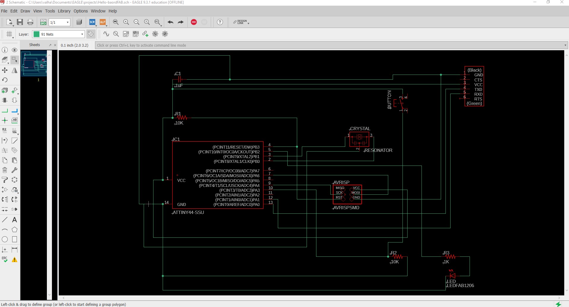
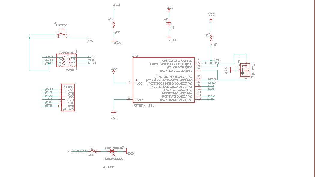
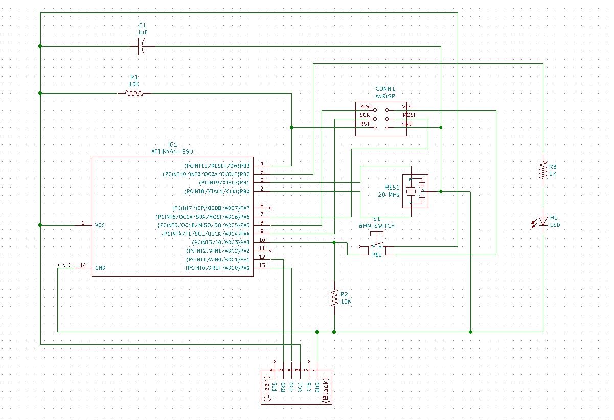
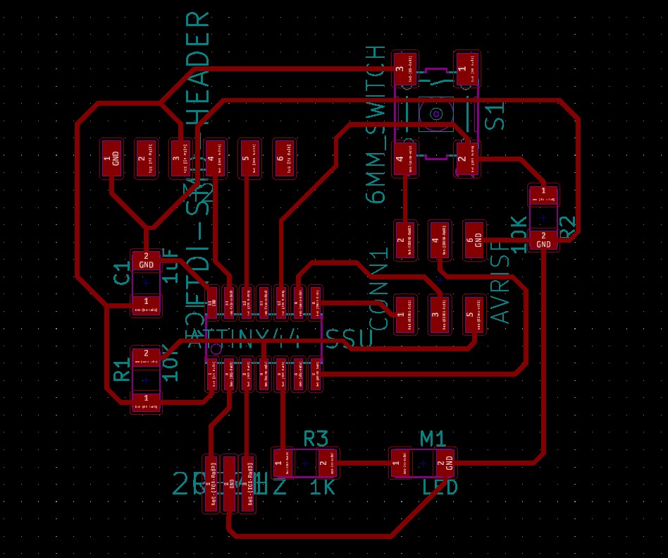
After a quick crash course with my instructor in Eagle CAD, I drew my first schematic and board, based on the Hello Echo board. 
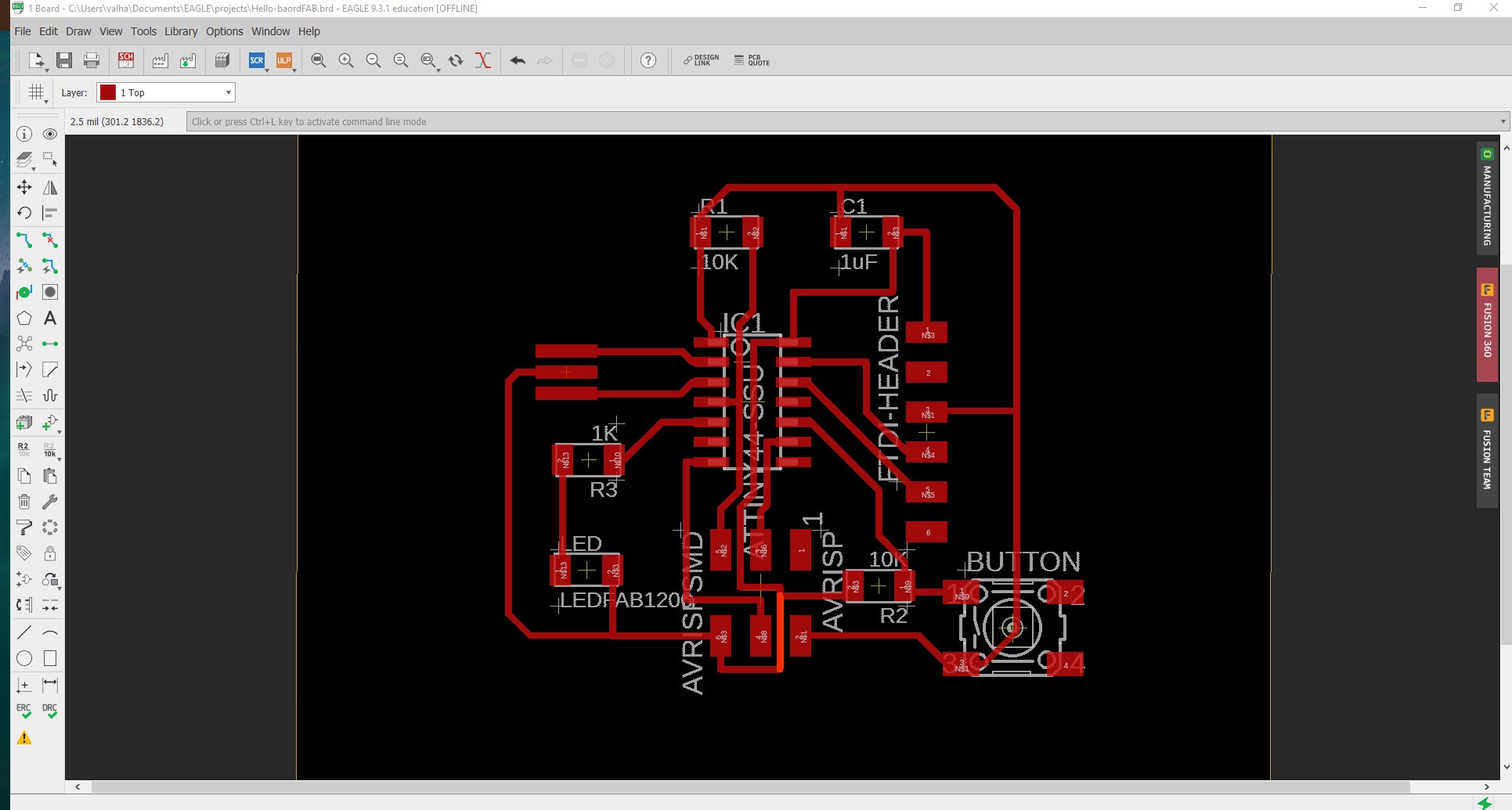
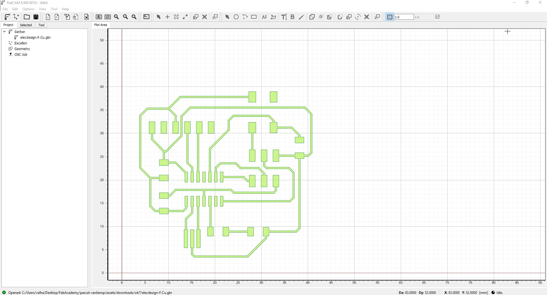
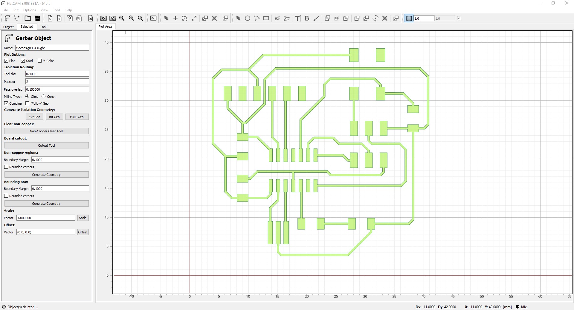
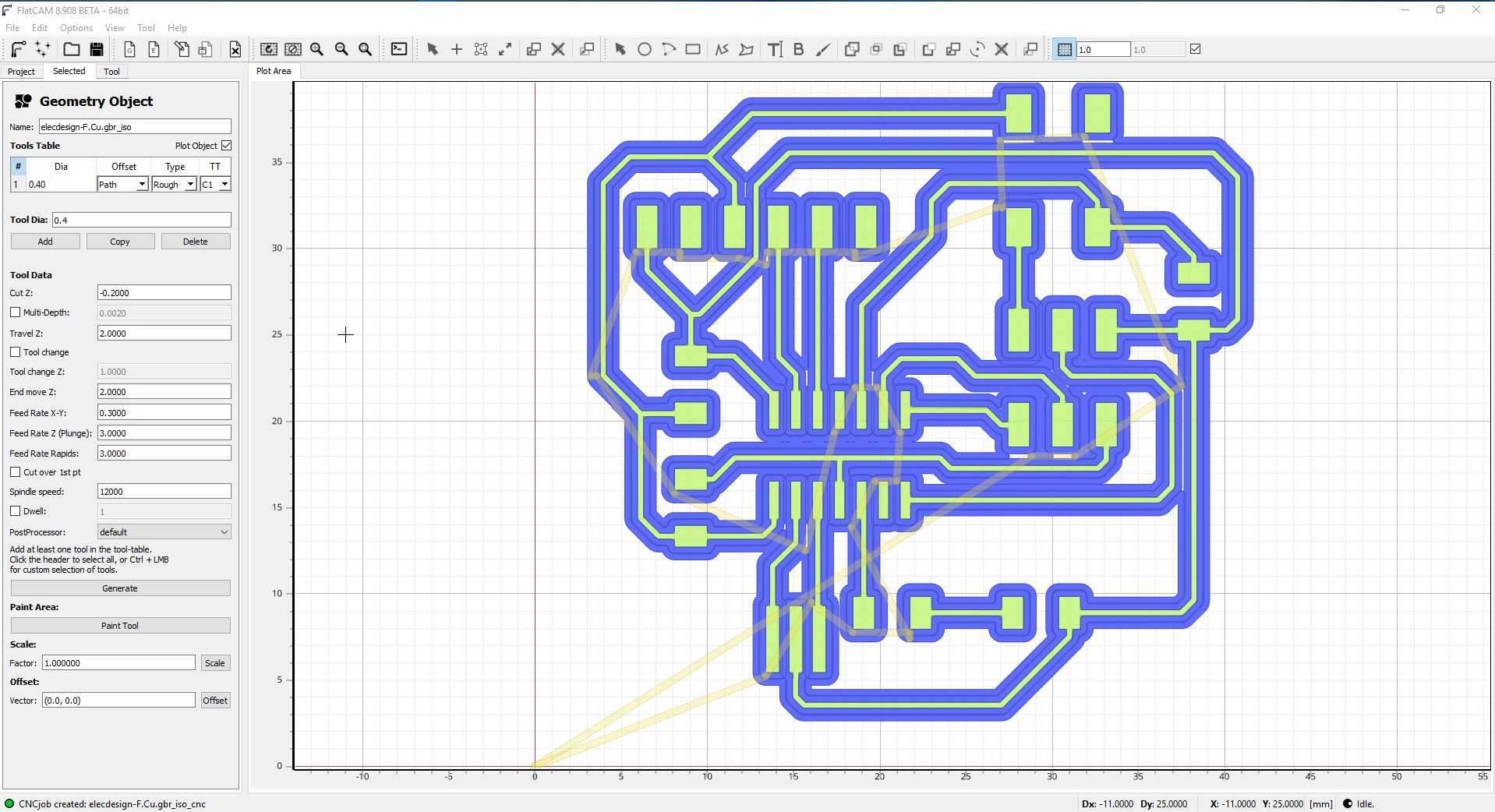
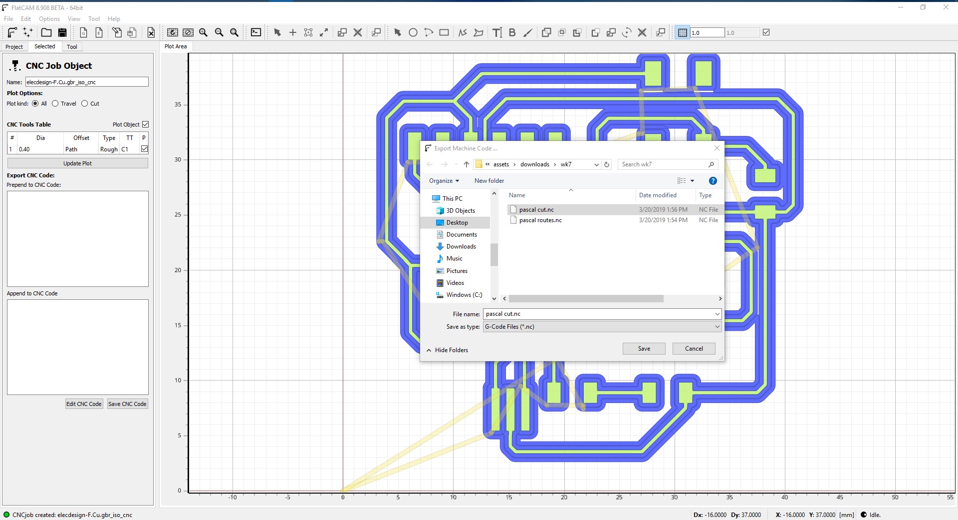
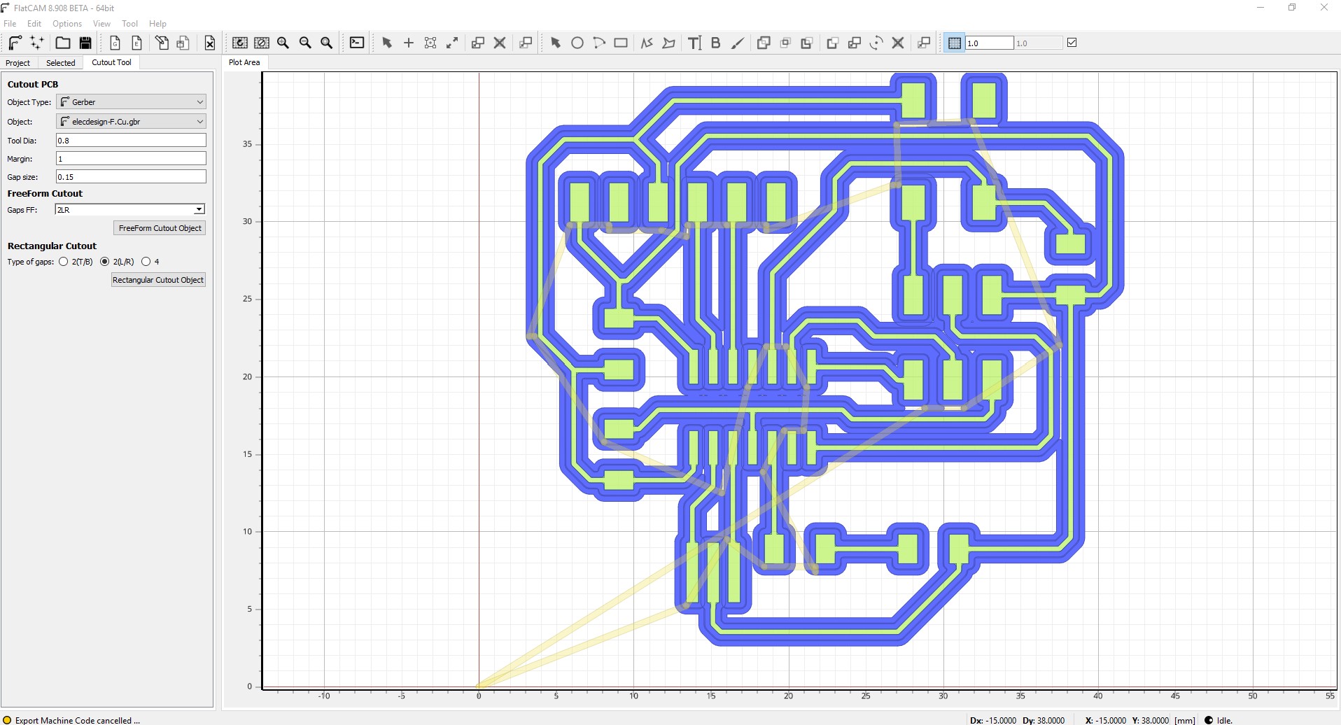
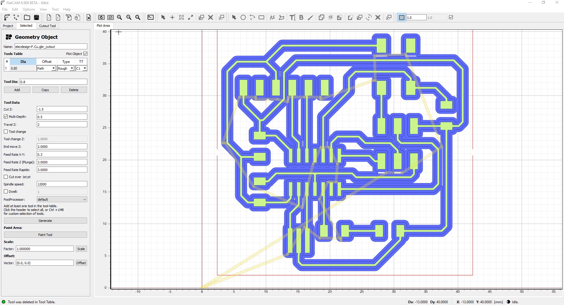
After completing the design, I exported the board, as gerber files and opened them in FlatCAM, to get them ready for milling.

The process will be explained a bit later on.


What went wrong

Schematic

First Schematic Drawing

Board Design

First Board Design

I was actually not too happy with how it turned out. But I was working in a rushed state, I wanted to get back on track as quick as possible.

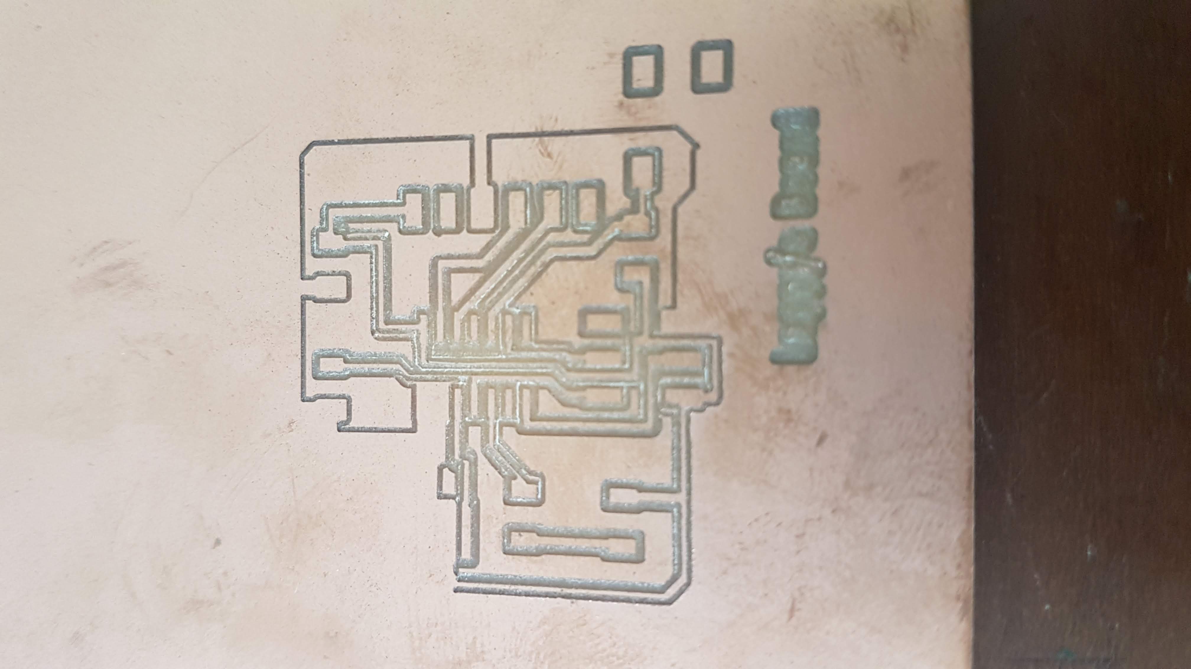
I was ready to mill my board and solder it, getting the PCB ready for programming.

However, I ran into a few issues, mostly to do with poor USB connection to the Stepcraft D.300 machine. I then retried with my own laptop using the WinPC-NC software, which came with the CNC router.

The second time, the depth was incorrect, breaking the bit. Bad luck? No, just working in a rushed state.

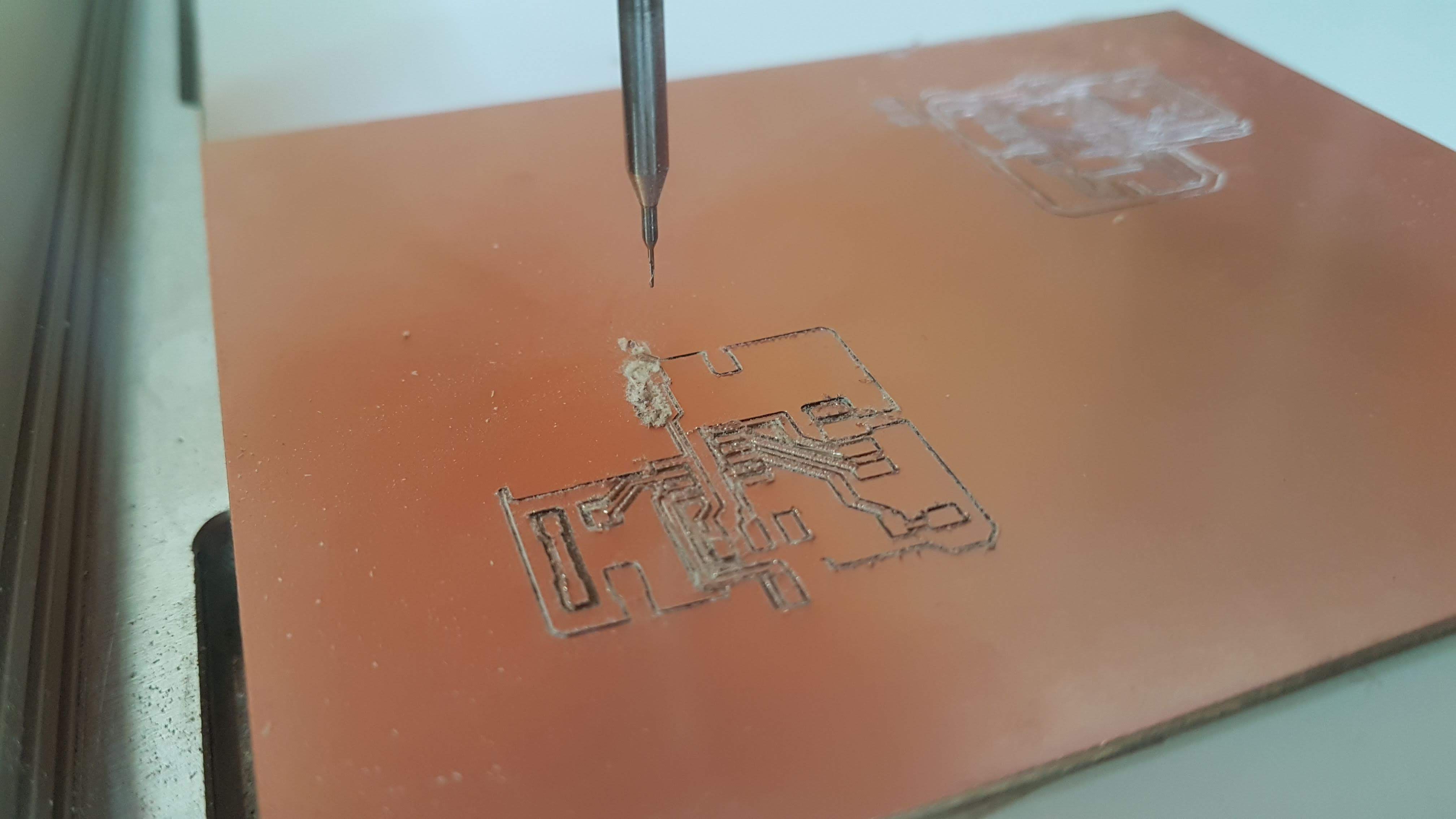
I tried for 2 more additional times, and the 4th time, it seemed I had the right settings. Up until 45%, the bit was cutting way too deep.

I could not find any wrong settings with the software, so I took a look at the machine.

The bit was slipping. I had not tightened the bit enough, creating vibrations and resulting in the bit slipping gradually.

Board Design

USB connection Lost.

Board Design

The result of the slipping bit

After a few failed attempts, I was getting pretty frustrated and decided to learn more about the process, which I failed to do, because of the virus that swept the floor with me.

These links were used for gaining more knowledge:

Libraries Used:


Starting with Redrawing the Hello Echo Board

Using EagleCAD

Using Electronics Design Automation Suites

To be fair, I donwloaded both KiCAD and EagleCAD just to get aquinted with both interfaces. KiCAD is free and open source and EagleCAD by AutoDesk has a free version, which does run cross platform.

I started with Eagle, becuase I wanted to have a try at a workflow, going form Eagle to Fusion 360 for a later stage of protoyping my final project.

Also experimented with the autoroute feature in Eagle, which seems to save time, but only when you have a sound drawn schematic.

What I did learn however is how to draw a schematic, just keep learning how to properly connect the part, to the proper components.

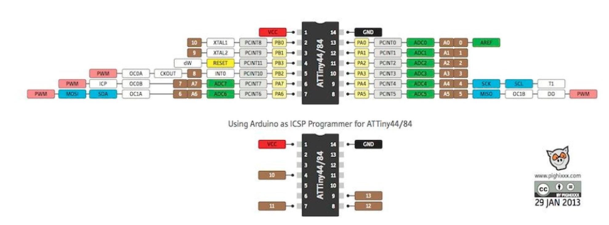
Learn how to use and draw a pull-down/pull-up resistor and read up on the MCU's pin layout.

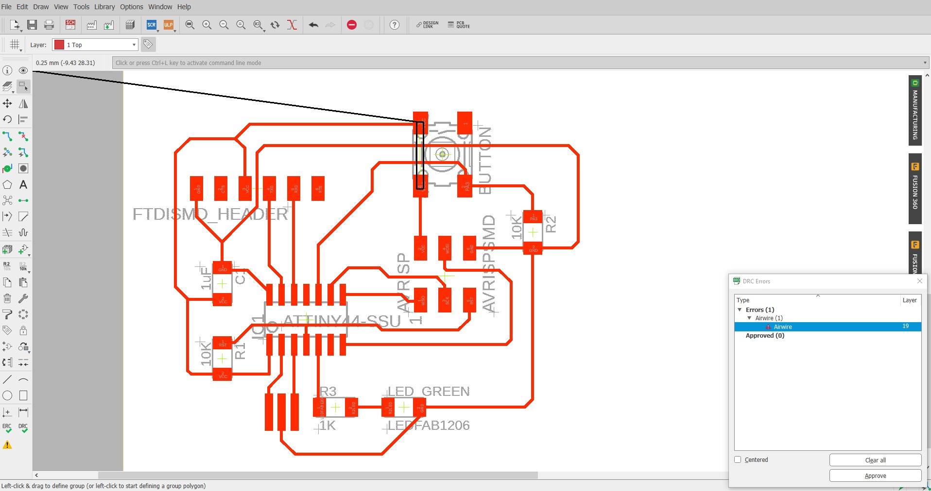
It seemed good enough, but there were still some issues with the design, and those issues were routing the button correctly.

After a sit down with my instructor we used KiCAD to correct this issue.

Afterwards I redrew it in EAGLE.

Eagle redraw

I used the information found in the tutorials

KiCAD redraw

This is the redraw in KiCAD the Instructor and I did.

KiCAD redraw 2

And this is the PCB route layout in KiCAD

PCB eagle redraw 2

This is the redraw in Ealge for the PCB. See the Airwire.


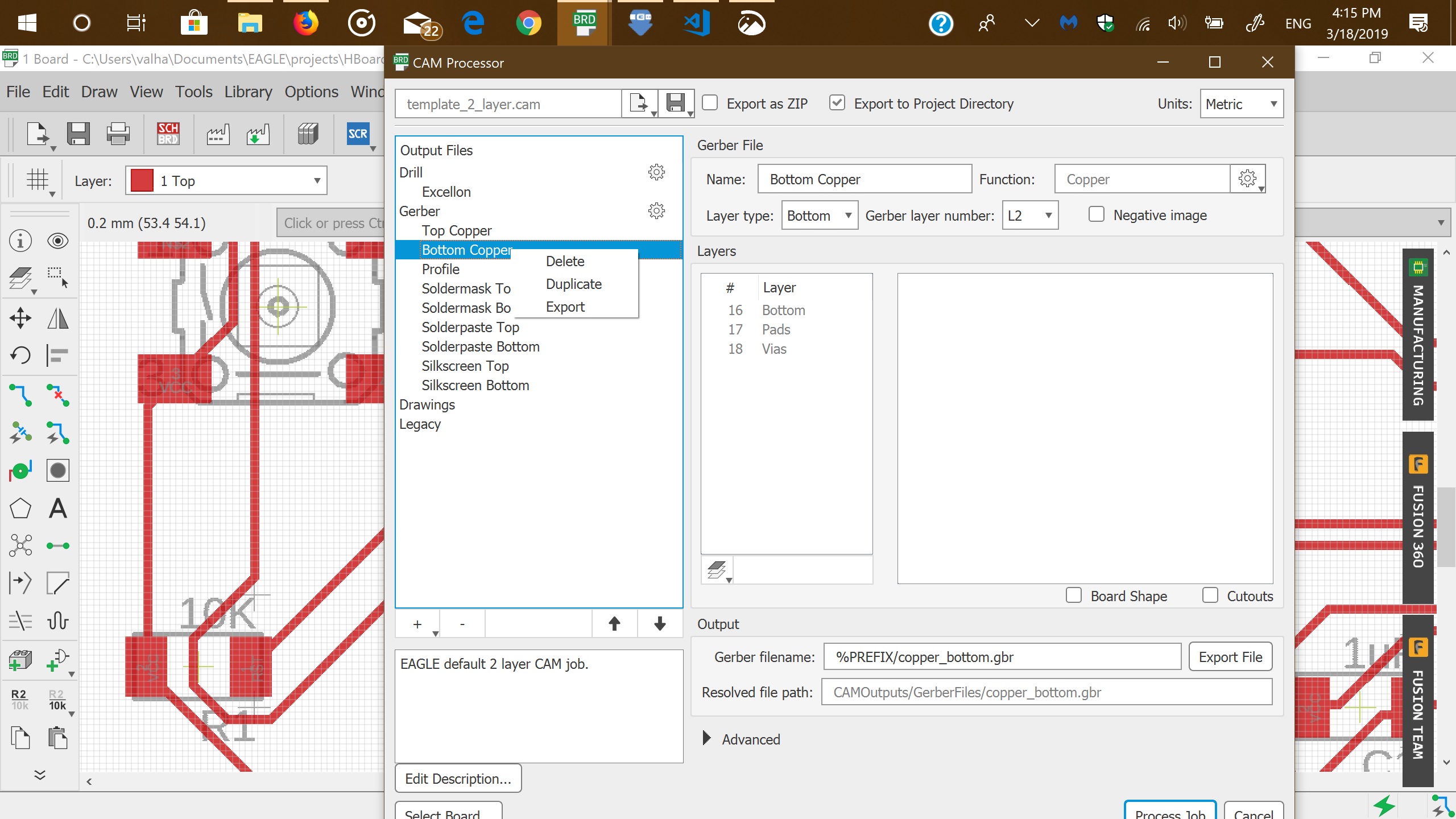
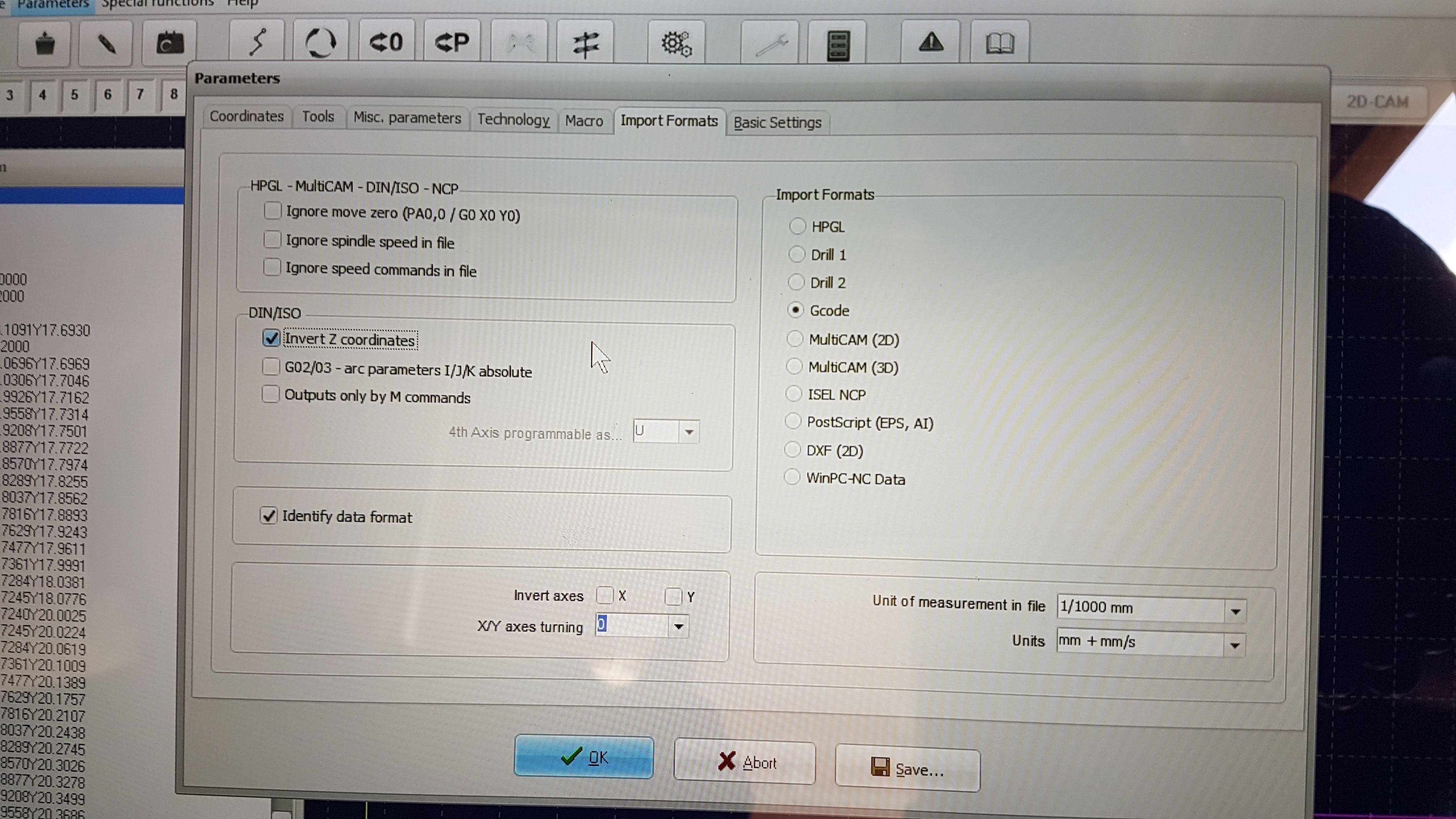
Now that we have our design, we need to export it as a gerber file. In EagleCAD this can be done by pressing the CAM processor (which looks like a factory)

Here I deleted all the other layers, except for the Top Copper layer. We can alsotell where and how your gerber file will be named and saved. (mostly dekstop for quick reference)

After we have clicked on the "Process Job" button, we can navigate to the location we defined in the CAM processor.

reference image

Remove all layers, not being used and generate your gerber file.

Downloads:

EagleCAD schematic

EagleCAD Board

KiCAD Schematic

KiCAD Board

Gerber Top Cu

FlatCAM

I used FlatCAM for creating the .nc files, required for the WinPC-NC software that comes with the Stepcraft D.300

Once FlatCAM is open go to the icon that looks like a F, in order to open your generated gerber file

Now we need to enter the tool, feedrate, spindle speed, travel of the z axis for the interior and exterior of the board.

The values that we used, for the interior plotting process:

  • Cut Z = -0.2 mm
  • Travel Z = 2.0 mm
  • Feedrate = 0.3 mm
  • Tool Dia = 0.4 mm
  • Spindle speed = 12000

And for the cutout plotting process:

  • Cut Z = -1.5 mm
  • Travel Z = 2.0 mm
  • Feedrate = 0.3 mm
  • Tool Dia = 0.8 mm
  • Spindle speed = 12000
  • Multi-Depth = True
  • Depth/pass = 0.5 mm

Gerber to FlatCAM

The Gerber file opened in FlatCAM


Interior Plot

Generate the interior plot, by selecting FULL Geo.


I used 2 passes and checked the combine option in order to have the 2nd pass in the same geography.

Interior Geo

The final plot for the Interior Geo


Save the .nc code by selecting save CNC code.


Save CNC Code

Save the CNC code, where you can easily access it.

From here, we can sculpt the model according to the reference image

Cutout

Now the Same procedure for the cutout


Cutout

We used a 0.8 mm bit for the cutout


Downloads, CNC files:

PCB Cut out

PCB Interior


WinPC-NC

WinPC-NC is an optional software (UCCNC by Stepcraft is the main tool) and is used for the milling of the PCB

After installing the software, we configured the software in order to optimally work with the machine.

WinPC-NC Settings

Settings for controlling the Stepcraft 300 better

WinPC-NC Settings

Settings for controlling the Stepcraft 300 better


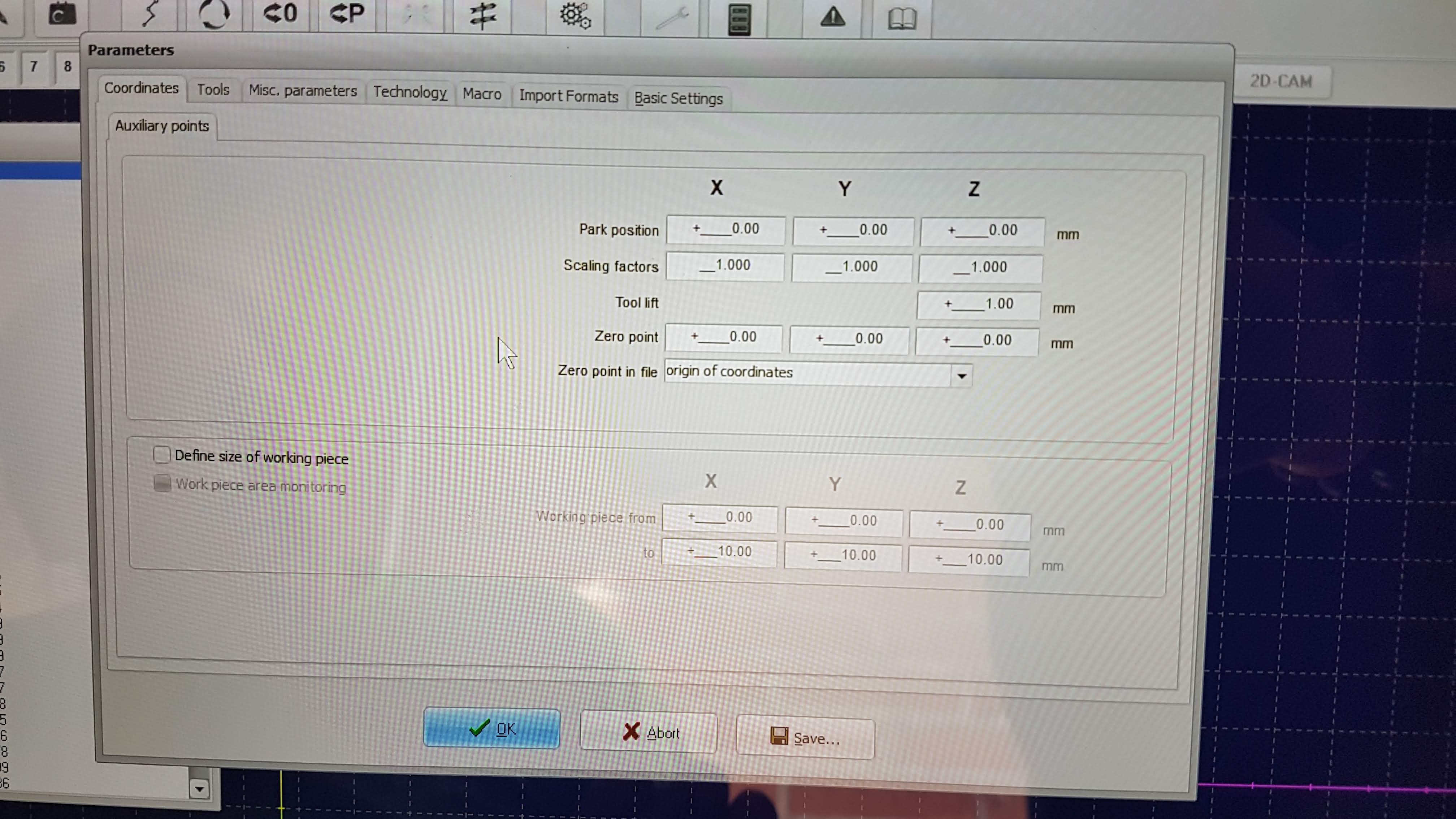
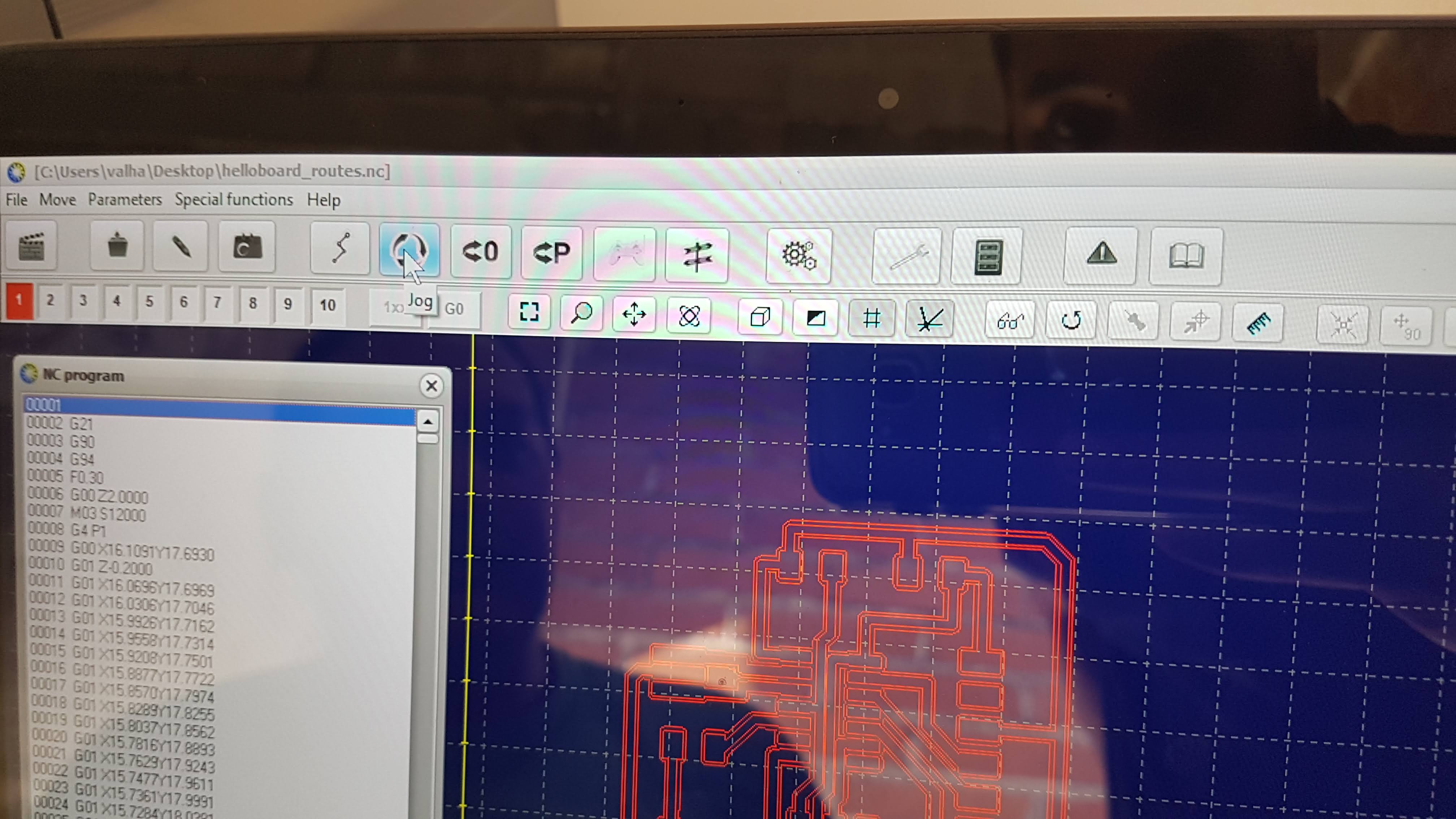
Afterwards, we import the CNC files we generated with FlatCAM and manualy set the 0 point position on the physical board. This needs to be measured just in case

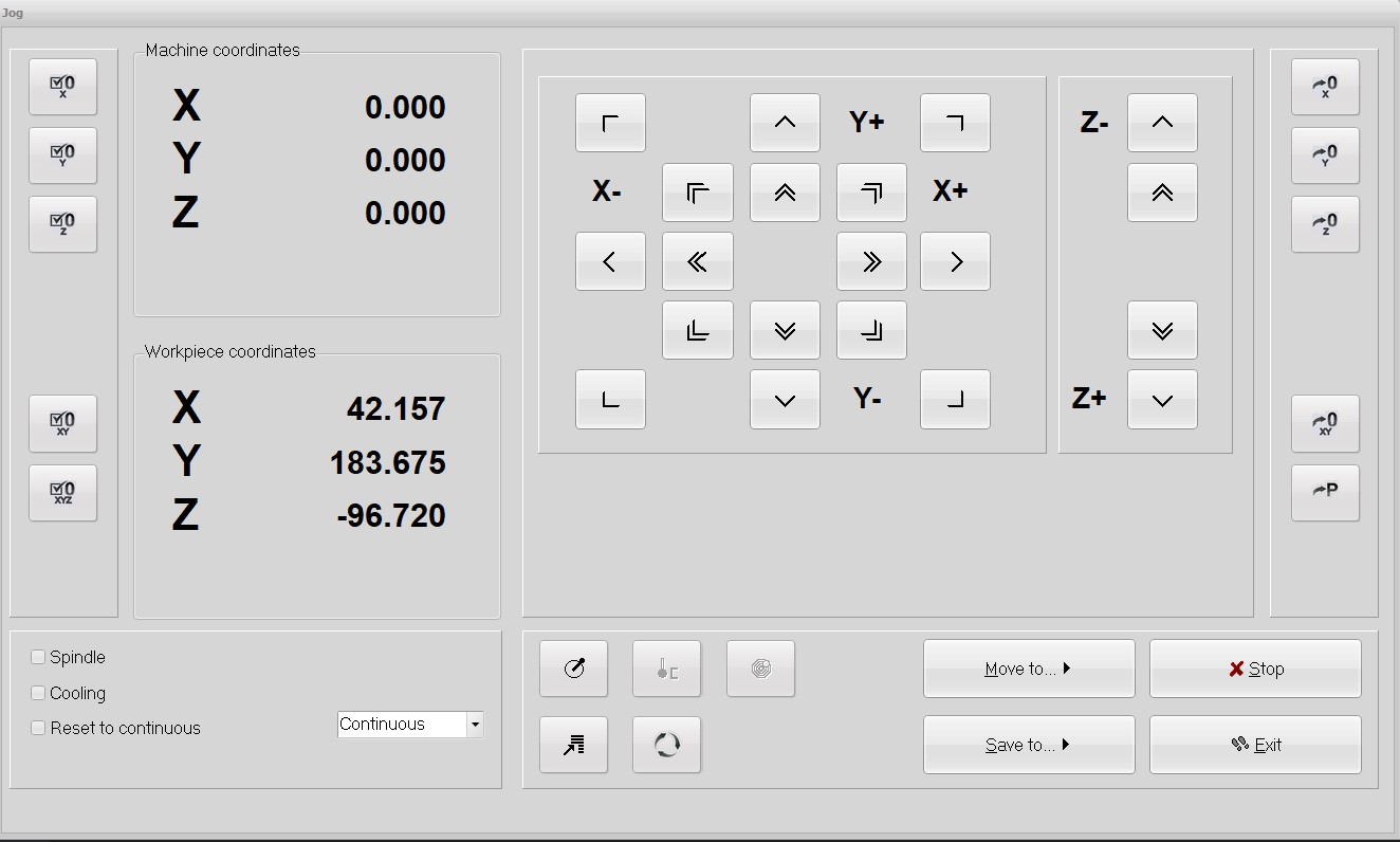
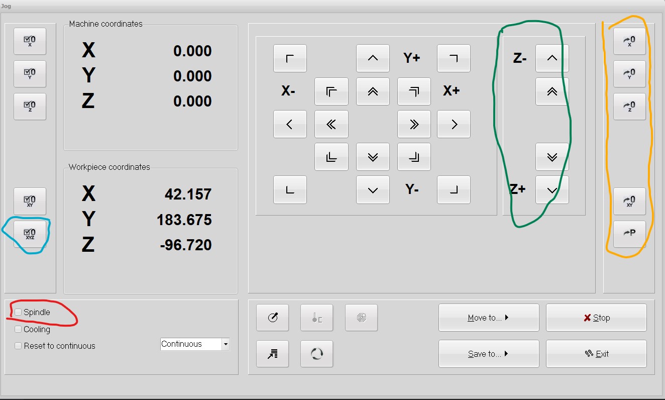
This is done by going to Jog and using either the arrow keys of your PC/laptop or the interface that pops up.

Careful not to confuse the Y and Z axes, because you might break a bit.

WinPC-NC Settings

Decide on the best position of the 0 point


WinPC-NC Settings

The Jog interface


WinPC-NC Settings

Using the Jog Interface

The arrow buttons are used for the the axes and the Z (Green) is used to take the HF-500 Spindle up and down.
Once the right position has been decided, click on the "set XYZ: (blue) button. In order not to break the bit, you can turn on Spindle (red). If something went wrong or a user error was made, you can always go back to your previous saved positions.

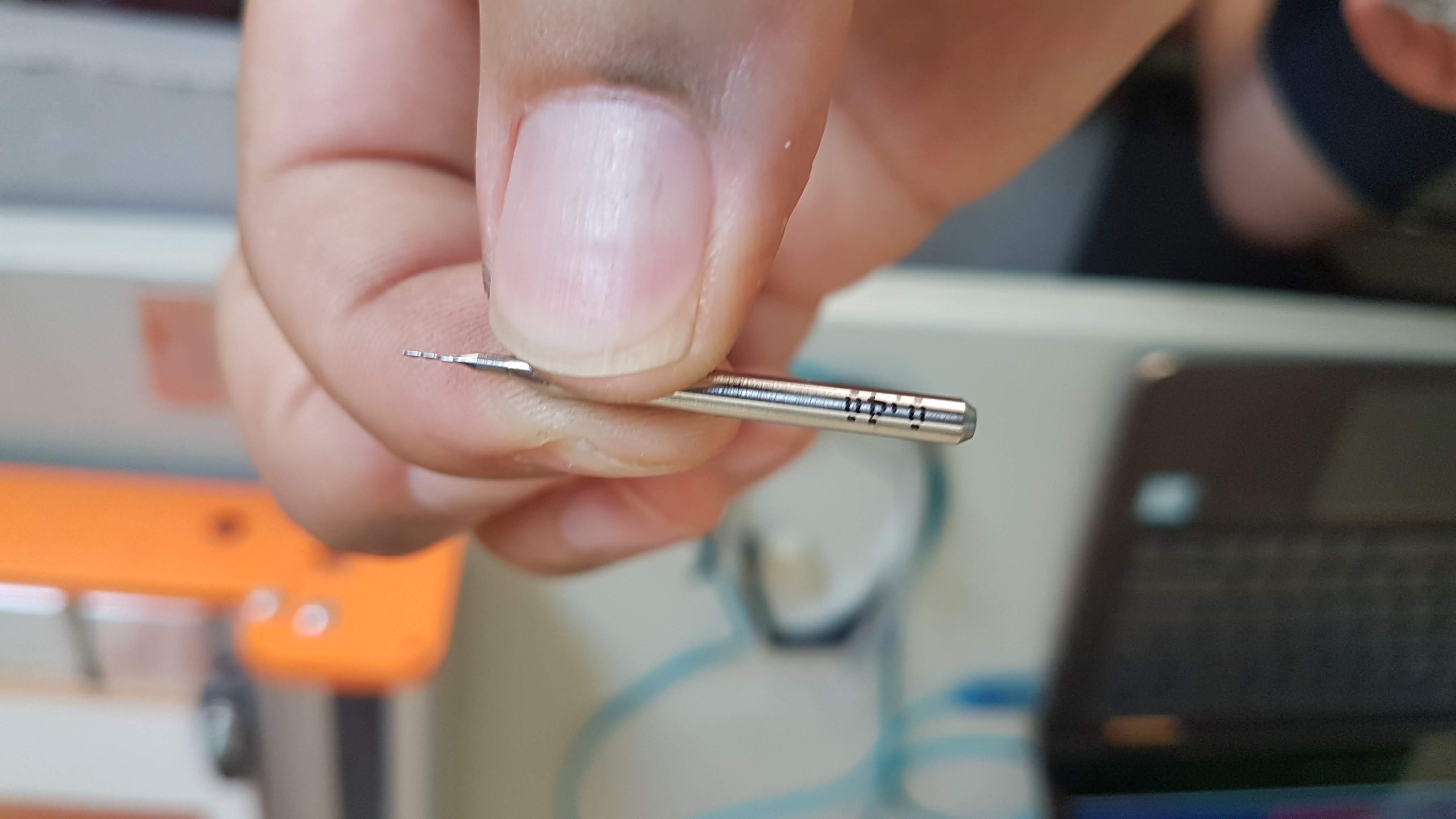
Select the right bit for the right CNC job. This bit is used for the interior of the PCB

WinPC-NC Settings

0.4 mm bit

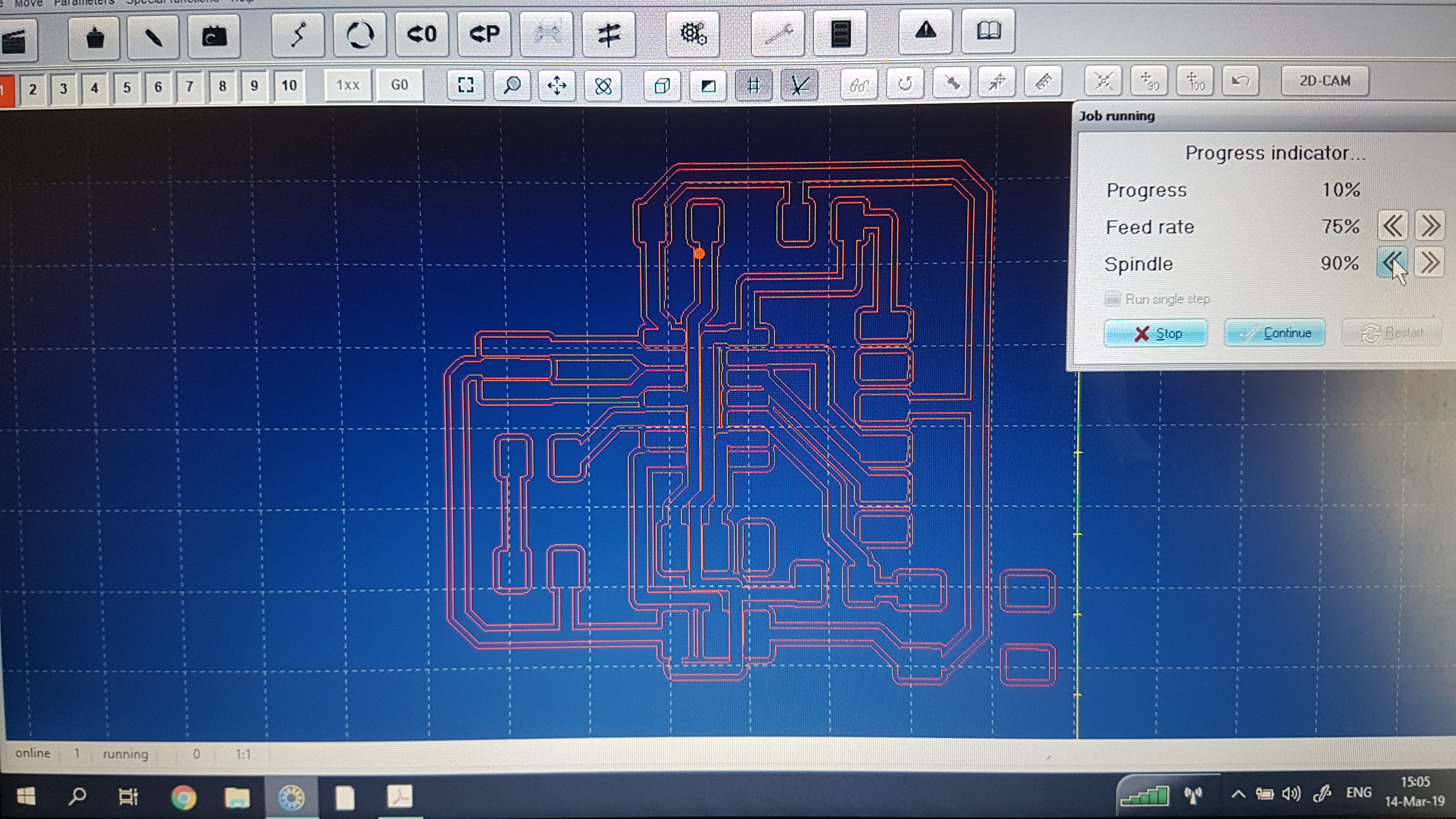
Once, the bit touches the board, you can exit and save the settings. Next to the Jog button is the start button.
Press start to initialize the milling process. And be vigilant at the reset button, in case something goes awry.

WinPC-NC Settings

Monitor the path just in case.

Programming the Board

After soldering the board, what next?

After I soldered the board, according to the design, we test and see if the board is funtioning correctly, We used a mulitmeter to check.

The con with using only a multimeter, is if things are not connected properly, you cannot see it on the meter.

This is one of the reasons, I could not burn my bootloader at first try, but more on that later.


I read up on the datasheet for the ATTiny44A in order to locate the Pulse Width Modulation Pin.

I used pin 8 for the PWM and LED, so whenever Pin 3 gets activated by the button/switch, I can use the PWM feature of pin 8 via Arduino IDE

errorbootload

The Pin Layout of the ATTiny44A

errorbootload

Locating the PWM Pins


In order to burn the bootloader to the PCB, I first needed to install the ATTiny44/A drivers on my laptop.

I used the drivers provided by Adafruit at this link

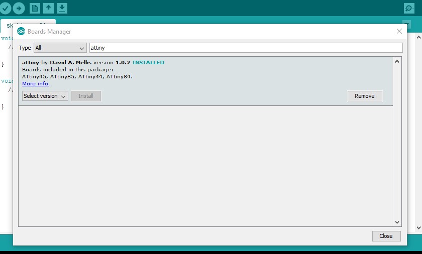
After installing the drivers, I opened the Arduino IDE, selected the "Tools" menu and navigated to the boards manager.
This can be found when hovering over "Board" , above "Processor".

When the manager window pops up, I filtered the ATTiny boards, by entering attiny in the search bar.

ATTiny Boards

ATTiny boards installed


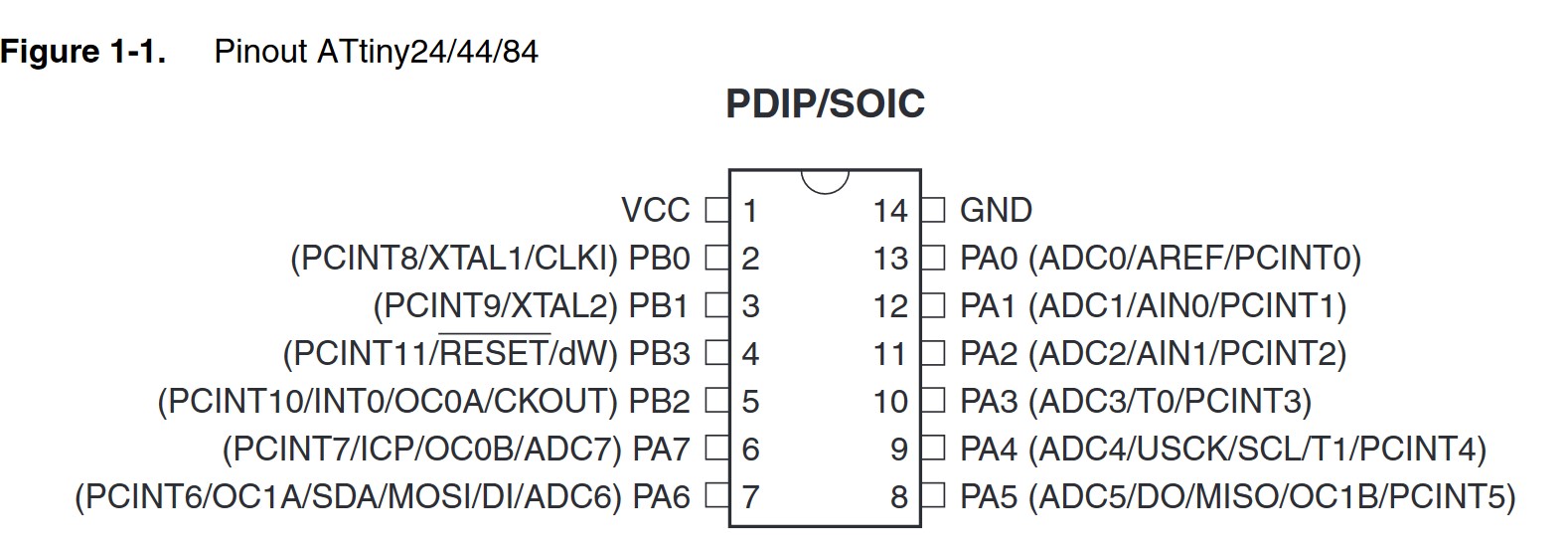
Now, we can configure the IDE to burn the bootloader to our board and in order to configure the IDE, we need to have read the datasheet at least once in order to understand what we are doing.

The settings are as following:

  • Board: ATTiny 24/44/84
  • Processor: ATTiny 44
  • Clock: 20 MHz
  • Programmer: USBtinyISP

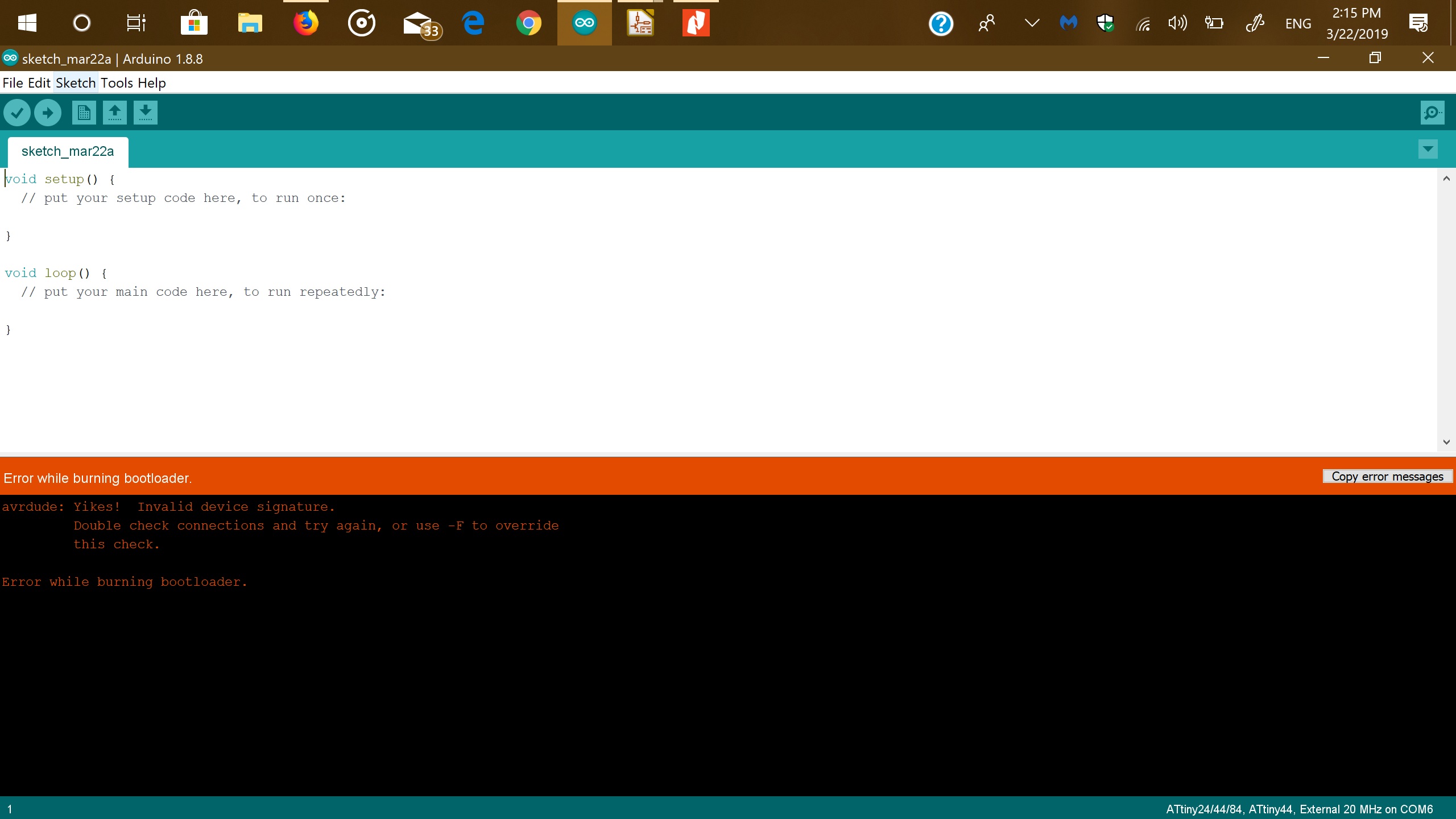
Double check, to see if your settings are correct and select Burn Bootloader


Troubleshooting

I recieved and error, stating that the connections might the issue.

errorbootload

Error burning bootloader.

After checking the solder, it seemed that there was a damaged track. After soldering a piece of leftover Cu, the bootloader was succesfully installed.


Also always check to postion of your VCC and GND pins. Switching them around, only creates unnecessary stress.

Blink the LED

In order to get aquinted with the programming, I opened a few samples, that come with the IDE.

These can be found under the File Examples and built-in examples.

I loaded up the sketch code, just out of curiosity if the LED would do as it is told and sure enough, it was blinking.

errorbootload

Quick look at the code.


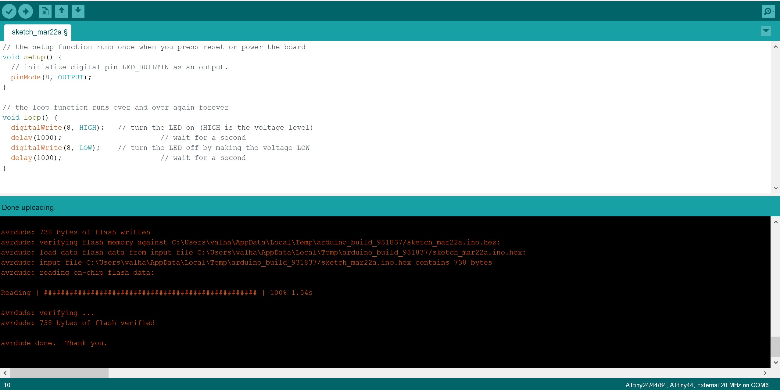
Program the LED to turn on or off with a switch/button

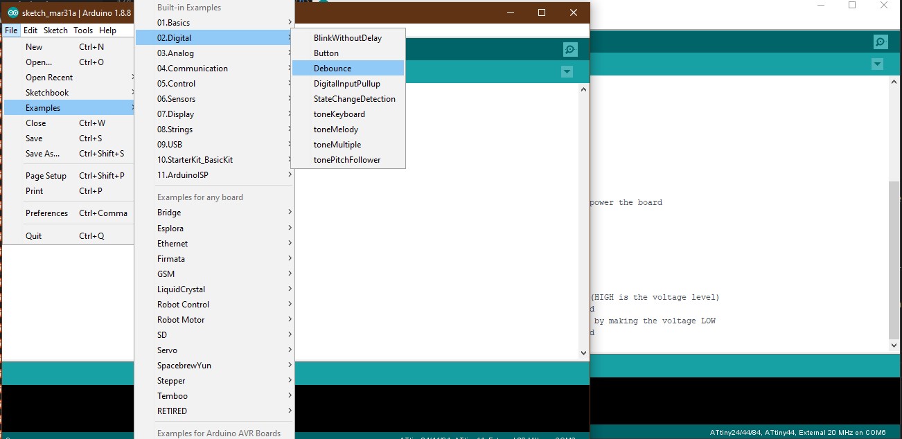
Again, you can use the built in examples to learn and understand. Loaded the code up to the board and the LED turned on as long as the button was pressed.

errorbootload

The Button example.

Using the PWM of the ATTiny44

After the examples, I decided to use the PWM for simulating an analog potentiometer. With this I can controll the LED brightness with a few clicks.

At first I did not understand how the PWM code worked, so I looked up a tutorial from Jeremy Blum

I had some issues, with the button not always turning on the LED. I concluded that it was a button bounce, Neil described, which created this inconsistancy and used a bool (true,flase) param, in order to elimante this.

I did not edit the code, just for educational reasons, to better understand the code.

Here is the code in text:

                              int switchPin = 3;
                              int ledPin= 8;
                              boolean lastButton = LOW;
                              boolean currentButton = LOW;
                              int ledLevel = 0;
                              
                              void setup() 
                              {
                                pinMode(switchPin, INPUT);
                                pinMode(ledPin, OUTPUT);
                              }
                              
                              boolean debounce(boolean last)
                              {
                                boolean current = digitalRead(switchPin);
                                if (last != current)
                                {
                                  delay(5);
                                  current = digitalRead(switchPin);
                                }
                                return current;
                              }
                              
                              void loop() 
                              {
                                currentButton = debounce(lastButton);
                                if (lastButton == LOW && currentButton == HIGH)
                                {
                                  ledLevel = ledLevel + 51;
                                }
                                  lastButton = currentButton;
                              
                                  if (ledLevel > 255) ledLevel = 0;
                                  analogWrite(ledPin, ledLevel);
                              }
                          

And here is the .ino download link:

The PWM Code


Hilfe Mich. Programming the LED to flash S.O.S Morse

I wanted the LED to flash Morse code, S.O.S and in order to do that I first had to read up on the conventions of Morse Code.

errorbootload

Morse Alphabet.

                              //SOS for LED, when pressed by Button:
                              int ledPin = 8;
                              int switchPin= 3;
                              int val = 0;
                              int s = 300;
                              int o = 800;
                              
                              void setup() {
                                pinMode(ledPin, OUTPUT);
                                pinMode (switchPin, INPUT);
                              }
                              
                              void character(int speed) {
                                digitalWrite(ledPin, HIGH);
                                delay(speed);
                                digitalWrite(ledPin, LOW);
                                delay(300);
                              }
                              
                              void loop() { 
                                val = digitalRead(switchPin);
                                if (val==HIGH) {
                                  digitalWrite(ledPin, LOW);
                                  for (int x = 1; x <= 3; x++) {
                                  character(s);
                                }
                                delay(100);
                                for (int x = 1; x <= 3; x++) {
                                  character(o);
                                }
                                delay(100);
                                for (int x = 1; x <= 3; x++) {
                                  character(s);
                                }
                                delay(2000);
                              } else{
                                digitalWrite(ledPin,LOW);
                              }
                              }
                          

I will go a bit into detail how I wrote the code and how some statements have been used.

The “for” statement
The “for” statement is used to repeat a block of statements enclosed in brackets. An increment counter is usually used to increment and terminate the loop. The “for” statement is useful for any repetitive operation, and is often used in combination with arrays to operate on collections of data/ pins.
There are three parts to the “for” loop header:

  • Initialization
  • Condition
  • Statement

So for the “for“ statement in the sketch:

for(int x = 1; x < 3; x++){

                            } 
                            

Step 1: Integer (whole numbers) value of variable x as 1
Step 2: Evaluate if x is less than 3.
Step 3: If it is valid, execute the following statement
Step 4: x increases and becomes 2.
Step 5: Repeat Step 2 less than 3.
Step 6: Repeat step 3
Until x = 3, the condition of x < 3 is not valid then the program skips over the code.
We set x < 3 to have it repeat 3 times. Calculating from 0 to 2, it repeats 3 times.
If we wanted it to repeat 100 times, we can use the following code: for(int x = 0;x < 100;x++){}
Some comparison operators like ">", "<" are frequently used in programming conditional statements. They will covered in more detail in the next section.


This is a section of a tutorial found here: DFrobot blog

I combined the button code with the Blink code, in order to flash SOS whenever the button is pressed.

Download the The SOS Code here.

Assignment Complete