5. Electronics production
- Group assignment :http://fabacademy.org/2019/labs/lakazlab/assignments/week05/
- Characterize the design rules for your PCB production process
- Individual assignment
- Make an in-circuit programmer by milling the PCB, program it, then optionally, trying other processes.
Objectives
- [x] Shown how you made and programmed the board
- [x] Explained any problems and how you fixed them
- [x] Included a ‘hero shot’ of your board
- [x] Screenshots and description of the process of using FlatCAM to create G-code from the ISP programmer traces image.
- [x] Parameters for milling the pcb: Cut z: -0,15mm Travel z: 2,5mm Feed rate: 0,5mm Tool diameter: 0.4mm Spindle speed: 10000 rpm
- [x] Describe the use of Winpcnc for executing G-code in the milling machine.
- [x] Make notes about the parameters you need to change in Winpcnc (invert z, origin of coordinates, and go back to zero point at the end)
- [x] Describe the process of attaching the pcb to the milling machine and setting the zero in x, y and z.
- [x] Mention safety rules
- [x] Describe the process of assembling and soldering the board
- [x] Describe the process of testing the board
- [x] Debugging the board
- [x] Mention any problems, errors or mistakes found in the board and how you fixed them. Program the board • Describe the process of programming the board.
- [x] Mention any problems, errors or mistakes found in the board and how you xed them.
- [x] Photo of your board.
Before it all started
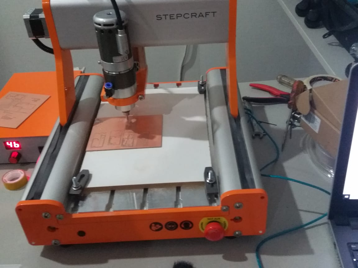
Electronics production week started with a major calibration of our Stepcraft D300 mill to make it accurate and fit for the job. Took us a full day getting it ready and and all things aligned as this is tedious work and almost a full take apart again. After that we were ready for milling PCB’s with 0.4mm end-mills.
Making what?
Ok we are making a programmer used to program other ATTiny based chips.
We produce the PCB from a given .png file and populate it with electronics, program it for its function
It all starts with this simple helloworld board
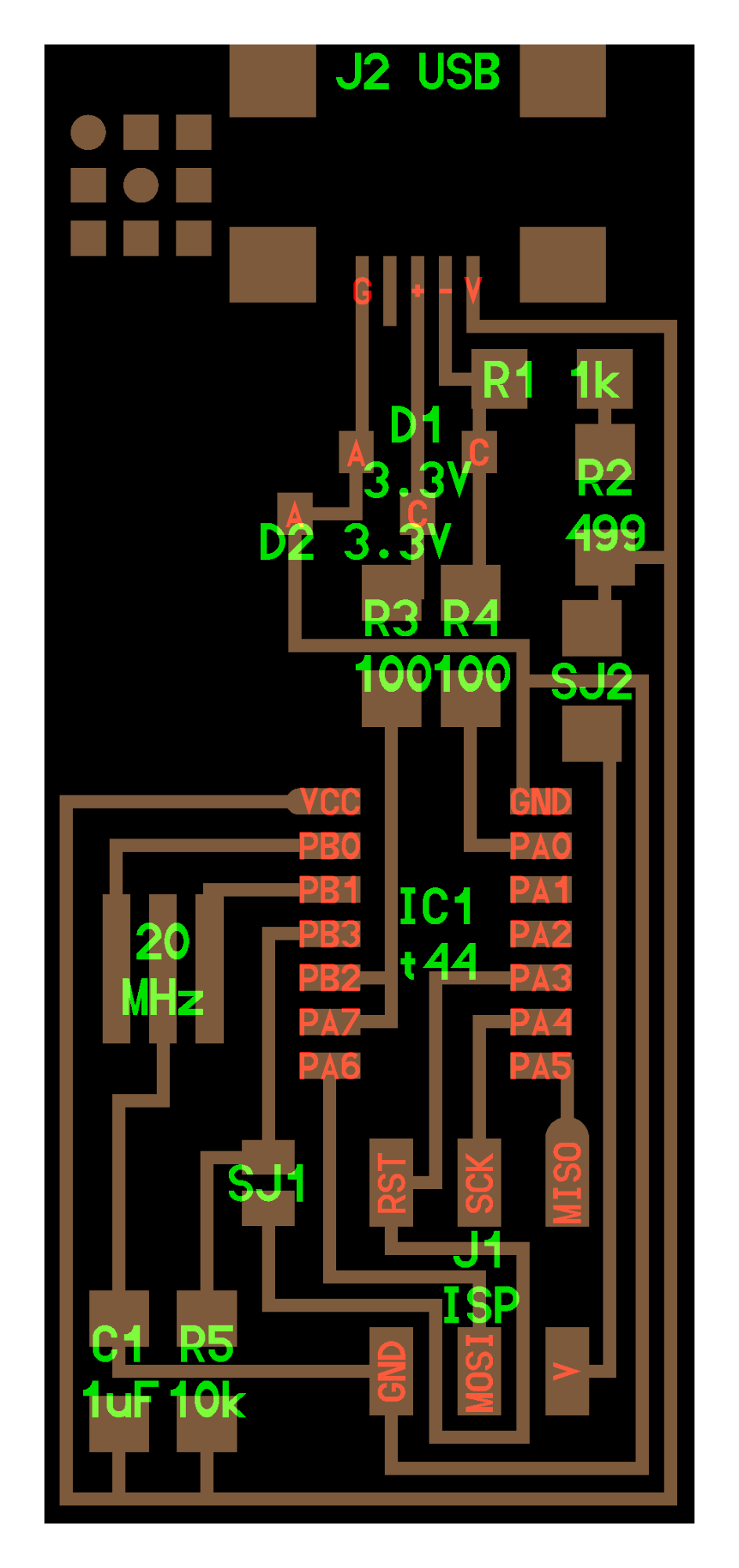
And a list of components:
- Atiny 44a
- Resonator 20 MHZ
- 1uF Capacitor
- diodes
- Resistors 1k, 10k, 499, 0 ohms
- AVRISP 2x3 headers
- Usb connector
PCB creation workflows
For Electronics production i tested 3 paths to see what works best in my situation.
Basic environment and constraints:
-
The mill Stepcraft 300 CNC, capable of great cuts but less supported
-
use as little as possible different softwares for CAD/CAM
-
I use a Mac
-
I choose Eagle as main PCB development environment and try as much as possible to go directly to mill
The workflows
A. file.png -> inkscape converts to -> DXF/SVG -> FlatCAM generates toolpaths & generates -> Gcode/nc -> WinPC-CNC sends gcode -> Stepcraft MIll
B. file.png -> FabModules generates -> Gcode/nc -> WinPC-CNC sends gcode -> Stepcraft MIll
C. file.png -> Eagle CAD run trace -> Stepcraft ULP Plugin for Eagle for CAM & gcode-> WinPC-CNC sends gcode -> Stepcraft MIll
A. Inkscape/FlatCam
InkScape
Inkscape is a free and open-source vector graphics editor. This software can be used to create or edit vector graphics such as illustrations, diagrams, line arts, charts, logos and complex paintings. The tool we use for generating vectors image from any pixel based image.
Steps:
- Import the *.png
- Use the bitmap trace
- Export to SVG or DXF as input for FlatCAM
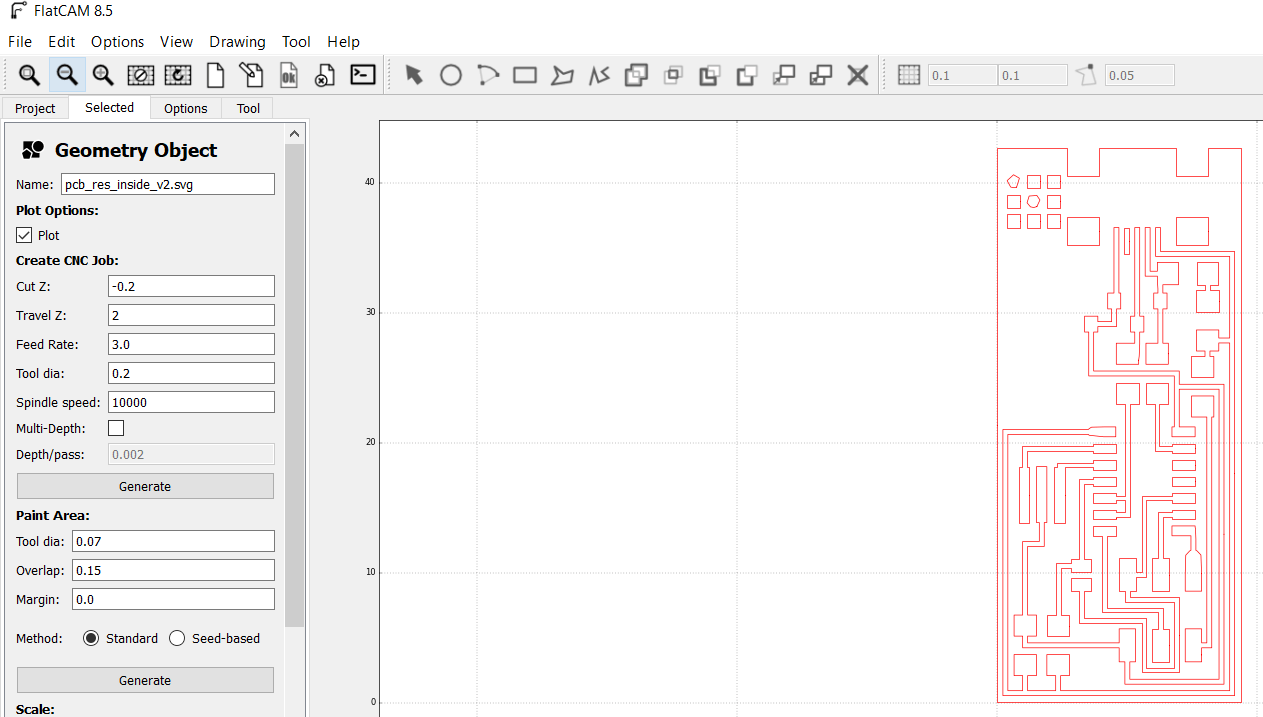
FlatCAM
FlatCAM is an OpenSource CAM tool that runs on Python. It’s purpose is create gcode from DXF or SVG or other CAD formats. It adds the process, machine and material specific settings to a design to prepare it for machining.
Open your generated DXF or SVG file in FlatCAM and view the paths.
Configured the CAM settings as below
| Settings | Value |
| Tool Dia | 0.4 |
| Cutz | -0.1 |
| travel Z | 2.0 |
| Feed-Rate-X-Y | 3.0 |
| Feed Rate Z Plunge | 0.5 |
| Spindle Speed | 10000 |
Generate GERBER files
Generate GCode / nc files
B. FAB MODS
FabModules is a browser-based CAM system, which allows to generate toolpaths for and control lasercutters, CNC-mills and waterjets commonly found in fablabs.
There is an online version available on http://mods.cba.mit.edu/
It is really easy to use and has recipes for CAM for almost all processes in the Fab Academy (like milling, pocket cutting, big cnc-ing etc) for most standard FABLAB equipment.
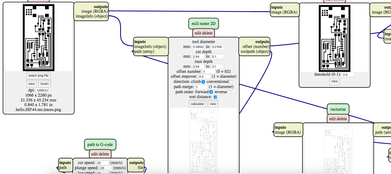
Our IoT Lab actually bought a Roland Modela MDX-20 specifically for this. At the time of Electronics Production week however we had not installed the unit yet so i just exported gcode instead and tried to import this code into WinPCNC.
The results of this import speak for themselves
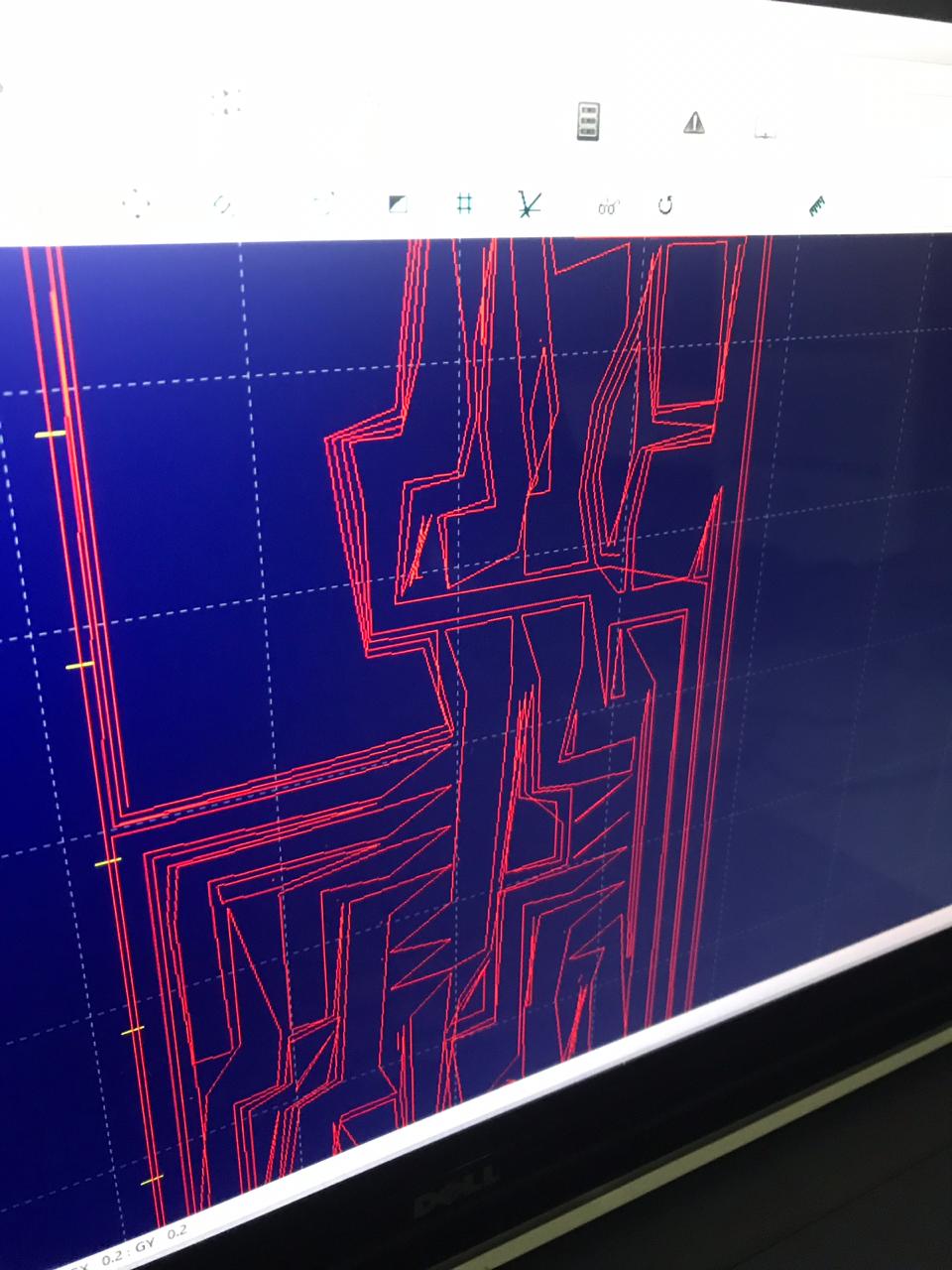
End of this road for now ;) .. to be continued
C. Eagle CAD
Eagle CAD offers a full PCB production workflow all the way from schematic capture, printed circuit board layout, auto-router and computer-aided manufacturing features. The learning curve is a bit steeper than the other tools but i found it to work great all the way to the end of actually creating the gerber files (containing gcode files for trace milling, holes drilling and outside dimension cutting).
Steps:
-
Convert the .png to .bmp as Eagle only imports from .bmp files. I converted .png to .bmp with Paint application. Open _”hello.ISP.44.traces.png”_using Paint >> Do a file>Save As>Change the save as type to .bmp as shown below.
-
Launch Eagle. Go to New>Board >> File>Import>Bitmap…>’select the bitmap file >> Scan used color> OK >> Under Unit, select MM, under scale factor, put key in 0.02. >> OK >> Run script.
-
Save the file as .brd.
-
Go to File>CAM Processor… >> File>Open>Job…>’gerb274x.cam’>Open. Under “Layers”, highlight ‘Top, Pads, Vias and Dimensions’ > Process Job. 2 files used in Protomat S103 will be generated, ie. .plc and .cmp.
I had to stop this effort however as i could NOT get the Stepcraft ULP script to pick a layer of my choice. Also i didnt understand how to move traces from one layer to another. So the exports only worked for the Dimension and drilling layers but NOT for the milling layer. I have a missing link here on how to work with layers.
WinPCNC / GCode sender
WinPCNC serves as the GCode sender tool and a monitoring & control pendant on your PC. It takes lines of the gcode file and sends them line-by-line to any connected CNC machine. It also allows for jogging to move NC machine tool-head to start coordinates (XY=0) and calibrate the workpiece zero (Z=0). It allows you to see the tool paths projected so jogging to extremes of each milling coordinate shows of the tool head stays within the substrate bounds.
Milling the board
We used the Stepcraft D300 for milling our PCB’s.
Important factor is to use a really flat and well braced sacrificial layer. We used a piece of MDF for that.
Determining the Workpiece Z-0 coordinate involves dropping the tool to roughly 5mm above the workpiece and slowly dropping it down to the surface with a piece of paper between the mill and the board. Keep moving the paper until some friction is felt then u are good to go. You Z is now zero (plus the thickness of your piece of paper ofcourse).
Another important issue that cost us a lot of broken end-mills is to make sure the Z-axis is set reversed in WinPCNC meaning minus (-) is down and plus (+) is up. This is NOT the default setting on WinPCNC.
Also check the gcode command and see that all lines starting with G0 have Z+xxx values and all with G1…G3 have Z-xxx values. Gcode is not that hard to decipher for anybody and in case you have to redo part of your milling (mill broke or so) with some digging you could resume the job from that position in de gcode file.
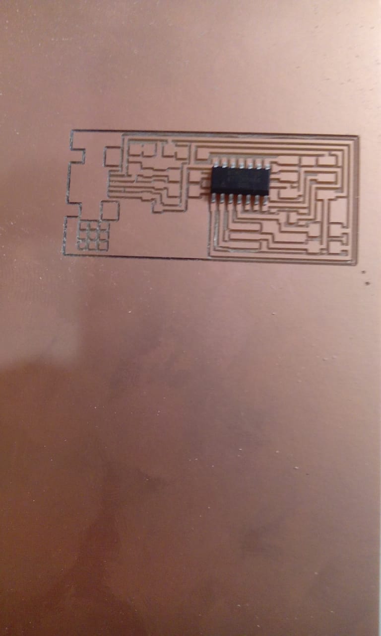
After milling the board it is always important to test the board with a multimeter
- Optically check the traces for discontinuities or shorts.
- Measure Vcc and GND traces to see if they short somewhere
- Clean up remains of copper millings that might still be in the milled areas
- Lightly sand down any skirts or uneven parts on the boards traces (this makes soldering a lot easier)
Soldering
As general rules
- Solder parts from Inside - out
- Small parts first
- Use solder one corner of a chip to hold down part
- Wet the solder tip add solder on joint and wait 10 secs for flow
- In case of mistakes desolder with copper braid
For this project i decided for my first time to test soldering with solder paste and a heat gun. It worked great after a few times of blowing off components completely. A good balance between air nozzle size, air flow & temperature and underlying bed temperature is very crucial. I’m still searching for this sweet spot though.
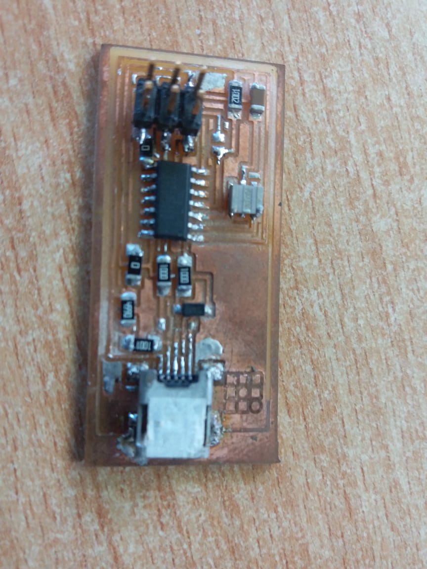
Programming the Programmer
Now that we have our FabISP soldered its time to put in the firmware that makes it work. We followed this documentation and programmed it from another FabISP programmer board. The following shows the set-up.
We tried for a while to program the ISP on the MAC with AVRDude but to no avail. We moved to an Ubuntu machine and it worked there
Ubuntu Terminal commands
$ sudo apt-get install flex byacc bison gcc libusb-dev avrdude (to intall Avrdude)

$ sudo apt-get install gcc-avr [type 'y' when prompted](to install GCC)

$ sudo apt-get install avr-libc (to intall Avrdude library)

$ sudo apt-get install libc6-dev (to intall Avrdude library)
Download & unzip the Firmware from this link nano Makefile (to edit the Makefile)
Remove the ‘#’ on the line within the usbtiny and add the ‘#’ on the line within avrisp2. File save after that.
The following steps are needed to compile the firmware
$make clean

$make hex

$make fuse
Last step is to program the board to be an ISP
$make program
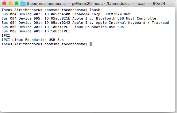
After finishing the programming remove the 0 ohm resistor connected to the reset pin of the ATTiny. Thereafter, plug the FabISP to your computer computer to check if the FabISP is detected.
On Mac OSX make sure you have the LSUSB tool installed and then run
$lsusb
Look for the line containing “Linux Foundation USB Bus” and you have a winner!
References
- Fab Academy Inspiration
- www.build-electronic-circuits.com/gerber-file/
- academy.cba.mit.edu/classes/electronics_production/traces.mp4
- academy.cba.mit.edu/classes/electronics_production/interior.mp4
Extra: Installing FlatCAM on MAC
I’m working on a Mac so i will share my experiences with problematic tool installs
Default method to install by FlatCam site
    brew install cartr/qt4/pyqt
    git clone https://bitbucket.org/jpcgt/flatcam.git
    pip2.7 install svg.path numpy simplejson
    ./flatcam
Tooling
Since i’m running on a Mac against all PC users here i will keep installation instructions for all tools that pose any problems from just click and install.
On another note since we all (8 of us) are going to work continuously in the IoT Lab i decided to connect all printers and CNC to the network using OctoPrint and alternatively open up an API for MOD linking
FlatCAM
brew install cartr/qt4/pyqt
git clone https://bitbucket.org/jpcgt/flatcam.git
pip2.7 install svg.path numpy simplejson
./flatcam
Got only errors at install so decided to run FlatCAM in Virtual 2.7 environment so i modded the .Py files:
Problems seems to be related to the QT4 libraries that are updated to QT5 since OS-Sierra.