6. 3D Scanning and printing
-
Group assignment was to Characterize the design rules for your 3D design and Print production process. group assignment
-
Individual assignment:
- Design and 3D print an object (small, few cm3, limited by printer time) that could not be made subtractively
- 3D scan an object (and optionally print it)
Objectives
- [x] Described what you learned by testing the 3D printers
- [x] Shown how you designed and made your object and explained why it could not be made subtractively
- [x] Scan an object
- [x] Outline problems and how you fixed them
- [ ] Included your design files and ‘hero shot’ photos of the scan and the final object
- [x] Screenshots and description of the process of making your 3d design.
- [x] Explain why your design cannot be made subtractively.
- [ ] Photo of your design.
- [x] Screenshots and description of the process of 3d scanning.
- [x] Described any problems during scanning.
- [x] Photo of your printed 3d scan (if you printed it, not mandatory)
- [x] Include all the les you created for download.
3D Printing
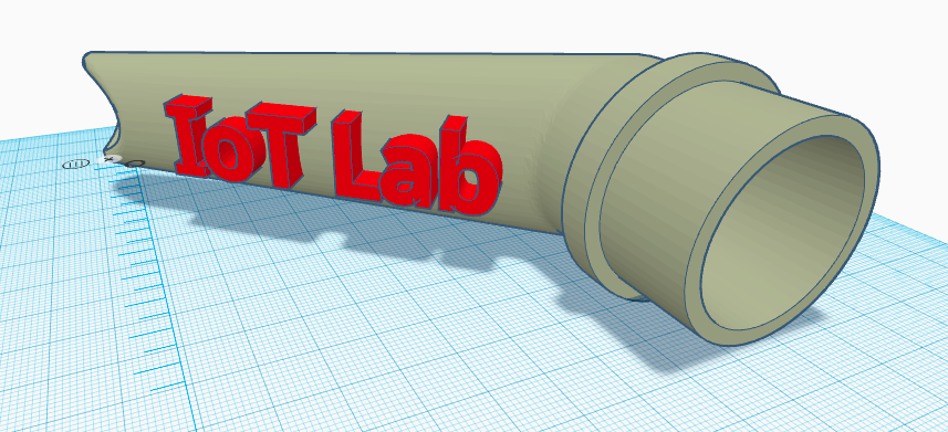
Modified Vacuum hose for CNC printer, added embossed text to the design.
For our individual assignment we have to design and make something with the 3D printer that could not be made with substractive manufacturing techniques.
Substractive manufacturing typically flaws on interior aspects of a design that or not reachable by tools from outside in or that have carves or channels on the inside. A lathe or CNC could only reach in straight in but when an internal curve has to be made its virtally impossible.
I used an existing design for a dust nozzle for our lab’s CNC machine. The design is borrowed from ThingsVerse and i added the IoT Lab logo beveled on the curved part of this nozzle. Also had to down-scale it for our own machine.
Why not substractively?
This nozzle could never be build substractively unless you add and extra 4th and 5th axis on your CNC machine. The nozzle is tubular and not uniform internal diameter on the inside. It also makes a bend between the two nozzle sections.
3D Design Tool
The tool used is Tinkercad as its very simple to use but has some serious capabilities applying boolean operations with objects as i used in my design.
Strategy was thus to use this mix of adding and substracting to create a perfectly beveled logo of IoT Lab on the double curved part of the nozzle. Instructions can mbe found here https://www.youtube.com/watch?v=3yzpv5HK-dg
Steps:
- Imported the vacuum hose into TinkerCAD (https://www.thingiverse.com/thing:846430)
- Added text IoT Lab and extrude slightly
- Position & rotate the text close to the object or section you want to bevel it on, and extrude it to fit on your target area and all the way through the target plane
- Create a containing box that completely contains the text object
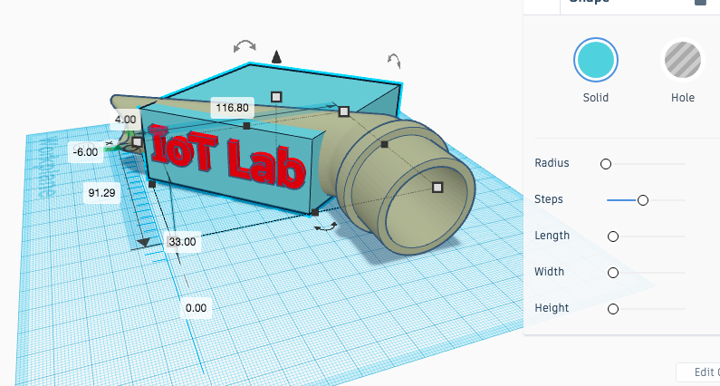
- Carve the text out of the surrounding box (hole) and merge them ( a negative image of the logo is created in a containing box)
- Duplicate the target object and merge with the negative text/box object, so now only the text based on the underlying curve is left.
- Move the text a bit forward, outside of the plane to create the beveling
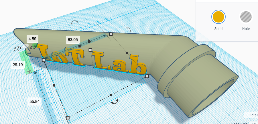
- Finally merge all objects before exporting to STL format for printing
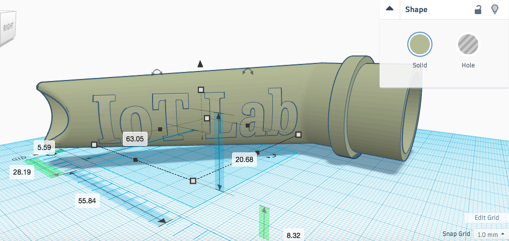
- For demo or just presentation purposes upload your STL file to SketchFab for review of potential issues with the design or with printing
3D Printing
Preparing 3D printing is done in CURA Steps: 1. Import STL or OBJ file 2. Scale and position your workpiece 3. Decide on your product orientation 4. Finally decide on printing parameters and things like fill, supports etc
Note: For printing i decided to tilt the mouth of the nozzle in the 3D design to lay flat so to reduce the need for printer support support. This idea backfired creating very rough bottom, actually when printing keep in mind the direction of slices to create a “nice serface”. See the other side of the print
3D Printing final result
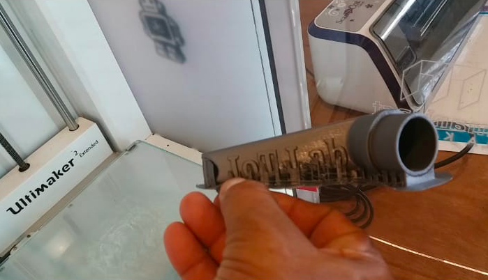 3D Print with supports
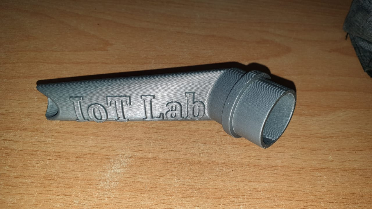 3D Print final result
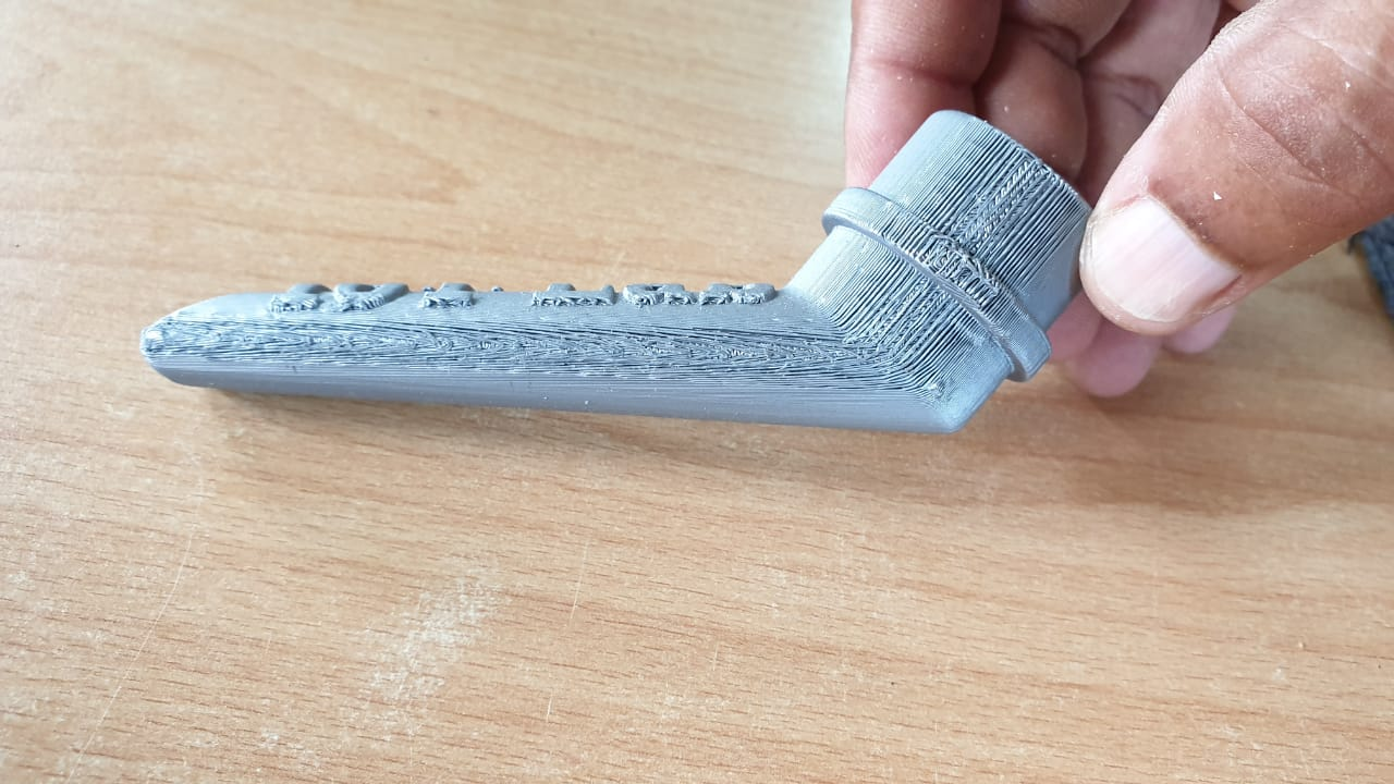 3D Print bottom results from resting the design directly on the printer plane
3D Scanning
Part 2 of this assignment was to make 3D Scan and we used the 3D Sense Scanner, a hand scanner for big objects. It saves files to STL or OBJ format.
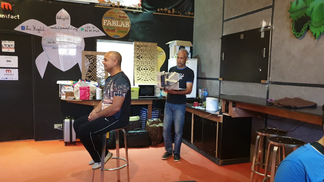
Steps are:
- Download the software for the 3D Sense and install
- Prepare objects for scanning
- Light conditions in the room, it is very important not to have bright lights or sunrays coming in at certain areas during the scan
- The software offers some presets for type of scans (eg full body or head ..)
- Selected full body we started scanning by walking around the object at a steady pace while keeping distance to object as constant as possible
- Following the screen for quality of captures you complete a full 360 degrees
- After this the software generates the full 3D object for review
- Export the model to STL or OBJ for further processing or printing
3D Sense Scanned Upload to SketchFab and embed in your site
3D Scanning Process Pros & Cons
- 3D Sense scanners allows to perform a quick scan of a bigger object that would normally not be easy to move around.
- The scanning is limited to circular type of objects and extending parts are often missed or misrepresented (in my case check the guitar neck & headstock).
- The setup we made connecting it directly to a laptop made us walk around the objects with a whole laptop, cables and the scanner.
- Light differences disturb the scanning process immensly so working in daylight would almost only be possible during noon or in cloudy weather
- We learned that you could also walk more than one time around an object to increase accuracy and detail IF the object is completely stationary
Download files
3D Scaning files (zipped STL)
3D Printing files (STL, OBJ en GCode)