12. Output devices
- Group assignment http://fabacademy.org/2019/labs/lakazlab/assignments/week12/
- Measure the power consumption of an output device
- Individual assignment
- Add an output device to a microcontroller board you’ve designed and program it to do something
Objectives
- [x] Described your design and fabrication process using words/images/screenshots, or linked to previous examples.
- [x] Explained the programming process/es you used and how the microcontroller datasheet helped you.
- [x] Outlined problems and how you fixed them
- [ ] Included original design files and code
- [x] Add link to the group assignment.
- [x] Screenshots and description of the process of creating your board.
- [x] Screenshots of soldering and debugging process.
- [x] Describe the programming of the board.
- [x] Photos or videos of your board working.
- [x] Describe any errors or problems with the process and how you xed them.
- [x] Include all the files you created for download.
Building a Step-Dir stepper motor driver
This week i built a ATtiny45 powered step-dir stepper motor driver that is capable to directly drive a Nema 17 and also offers a built in end-stop detection circuit and logic. My personal goal is to minify the stepper controller by combining detection, step-dir and stepper control into the ATtiny45.
I used a design i found on Instructables for a simple step-dir controller based on ATtiny45 that allows for simple control of your stepper motors by just passing a pulse for each step and setting another pin for the direction. I also followed this article on increasing ATtiny45’s inputs by multi-use of IO’s
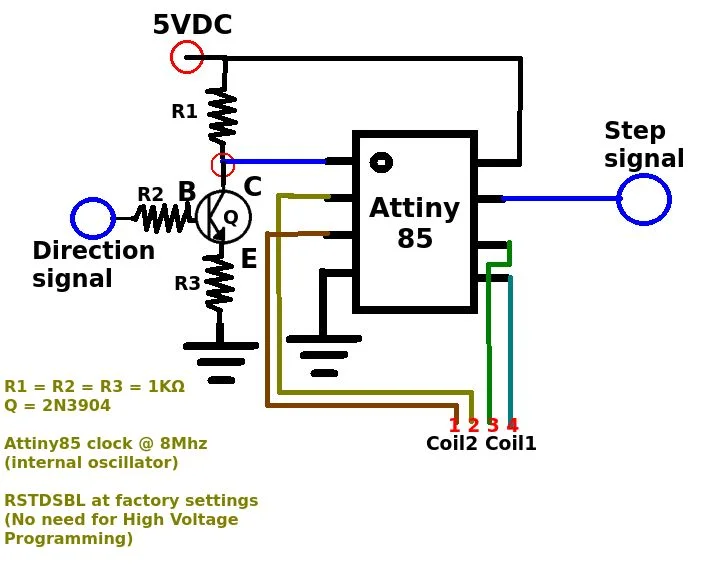
They use all the IO pins of the ATtiny plus the reset pin aka. “soft IO” mentioned in the Datasheet to create a very nice compact design for stepper control.
Integration of designs
1.The Power Motor Drivers
First off you need more power to steer a Nema17 stepper so we will integrate some power motor driver chips and integrate the circuitry of the FabLab Hello Bipolar stepper driver but then leaving out the ATtiny44 and so to drive it directly from the step-dir controller based in the ATtiny45.
2.The end-stop sensor (wk11)
The end-stopper circuit is a challenge to integrate because all of the IO pins on the ATtiny45 are already taken and the direction pin already hijacked the reset-pin.
Only pin left to hijack for the end-stop was the “step-pin” by means of disabling the step functionality with a PNP transistor when end-stop is reached (hardware disable).
But then we have NO step functionality left to continue in that direction as all step pulses are ignored from there on, but that’s the whole idea of course.
But then the system is stuck and we cannot move backwards either, now that’s a problem!
This we will solve in the firmware. The stepper driver and end-stop sensor will work together on this and the stepper will be software triggered to jog slowly in reverse direction until the end-stop disable status has been resolved. This is the position one step before the end-stop sensor touch ofcourse. Now the software will NOT accept any new steps in that direction (software disable).
Design of the Board
This week i build forward on the board created in week 11. I decided to split the main controller board and the specific sensor board/ In version 2 I already factored in the 4 output pins for Stepper control.
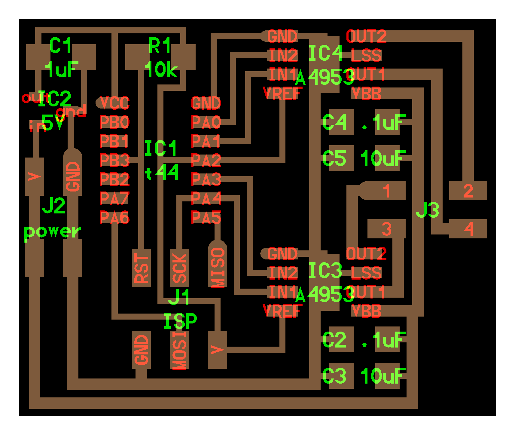
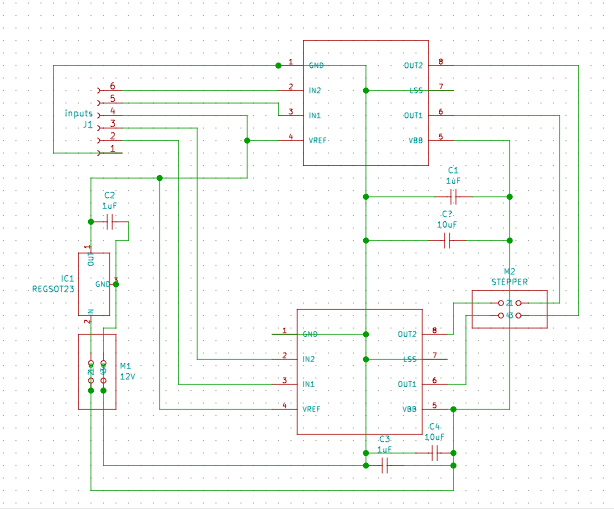
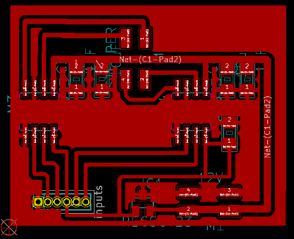
The final schematic & PCB design of the main-board
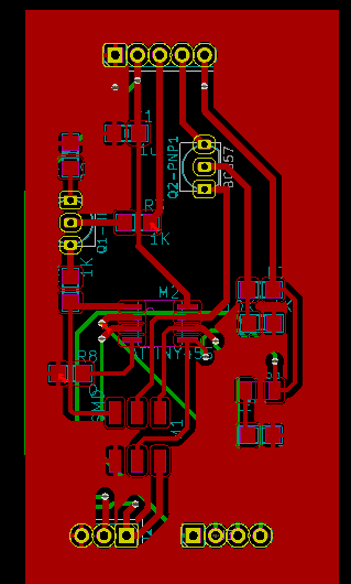
This mother board would already be capable driving of self-powered Stepper Motors (via their own power controller) but the goal here is to add a daughterboard with all the power transistors on board to directly drive at least a Nema17 directly.
Schematic of the Motor Driver daughter-board
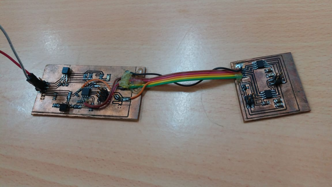
The resulting Step-Dir Driver board combo
Programming the board
We are happy that both the Instructables and the Hello.stepper came with example code we could start off from.
Code block commented
    volatile byte curStep = 0;
    byte coils[] = {0, 1, 3 ,4};
    /*  ATTINY45 PINOUT  */
    #define stepPin 0       //pin7 - PORTB 2 (interrupt 0)              --Used as Interrupt (so 0)
    #define dirPin 0        //pin1 - PORTB 5 (analog 0) - Reset pin    --
    /*
     *    The threshold that identifies if a signal is high or low. It is inside [0, 1023].
     *    For Attiny 45 this has to be the reset pin connected to a Transistor and resistors. It has to read the "low"
     *      but not Reset your microcontroller...
     */
    #define highThreshold  829
    /*
     *    Stepper motor coil states.
     *      States with more than one HIGHs are halfsteps
     *    Dead state is the state that no current is sent to the motor.
     */
    byte steps[8] ={
      0b00100001,
      0b00100011,
      0b00100010,
      0b00101010,
      0b00101000,
      0b00111000,
      0b00110000,
      0b00110001,
    };

    byte dead = 0b00100000;

    void setup() {
      DDRB = 0b00011011;
    /*  Triggers the count() function whenever a step signal is received  */
      attachInterrupt(0, count, RISING);
    }

    void loop() {}

    void count(){
        if (analogRead(dirPin) > highThreshold)
            // If step receiver and treshold above value step backwards in sequence
            PORTB = steps[--curStep % 8];
        else
            // If step receiver and treshold below value step forward in sequence
            PORTB = steps[++curStep % 8];
      }
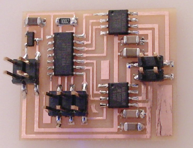
The board operational here (with leds to show the coil switching sequence)
Problems & Solutions
No SMD Transistors
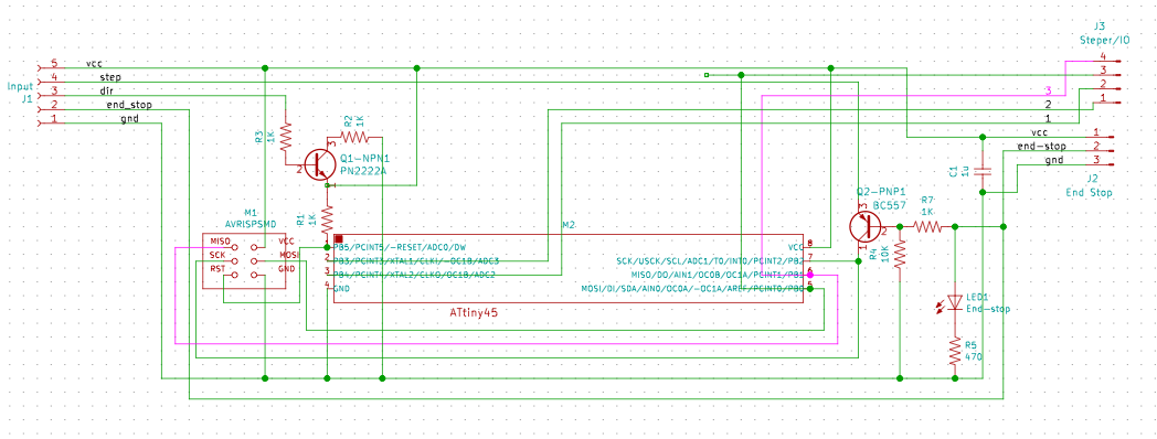
Schematic used transistors and we don’t have any SMD type on stock so i had to be creative with standard form transistors we had available to fit them on the footprint of the SMD version. Some hot-glue to keep things tightly together from my past experiences with traces breaking off. I used standard NPN (2N222) for the Direction pin and PNP (B557) for the End-stop / Proximity sensor.
Reset Pin Soft I/O
The issue with using the reset pin is that it constantly resets the mcu if something fails. So in this scenario care should be taken not to drop the reset pin voltage below 1.5V
As the Datasheets suggest the Reset Pin of the ATtiny could be used as a “soft input”. In this design it doubles as the “Direction pin” of my Step-Dir controller. Only requirement of using this pin is that the voltage NEVER DROPS BELOW 1V.
I created a (Vcc plane since it was completely isolated from ground or any other pins by bridging it with a 0-ohm. From there i corrected the 1k ohm voltage bridge leg for the Reset trigger prevention.
Combining end-stopper with step-dir
Cobining week 11 end-stopper / distance sensor combo on the step pin is extremely challenging. It would be easier to just use a AtTiny44 with plenty of pins instead.
What i came up with is:
If end-stop is hit the step-functionality gets blocked automatically via the PNP transistor that sits between the step pin and the AtTiny pin. Problem now is that we cannot detect the steps anymore so the code should make a step back (-1 or +1) depending on the last step direction requested. This will re-enable the step functionality after notifying the code and triggering software-end-stop has been reached so code will block any further steps in that direction.
For the distance sensor we added these lines so we know we will be hitting end-stop status soon
On-board pulse generator (wish-list / future work)
In testing i already realized that for testing or maybe even “live jogging” of the stepper controller system it would be nice to van a small on-board function generator to generate the input pulses for the step-dir controller. Preferable with a simple pot-meter that could jog forward/backward and speed in one knob.
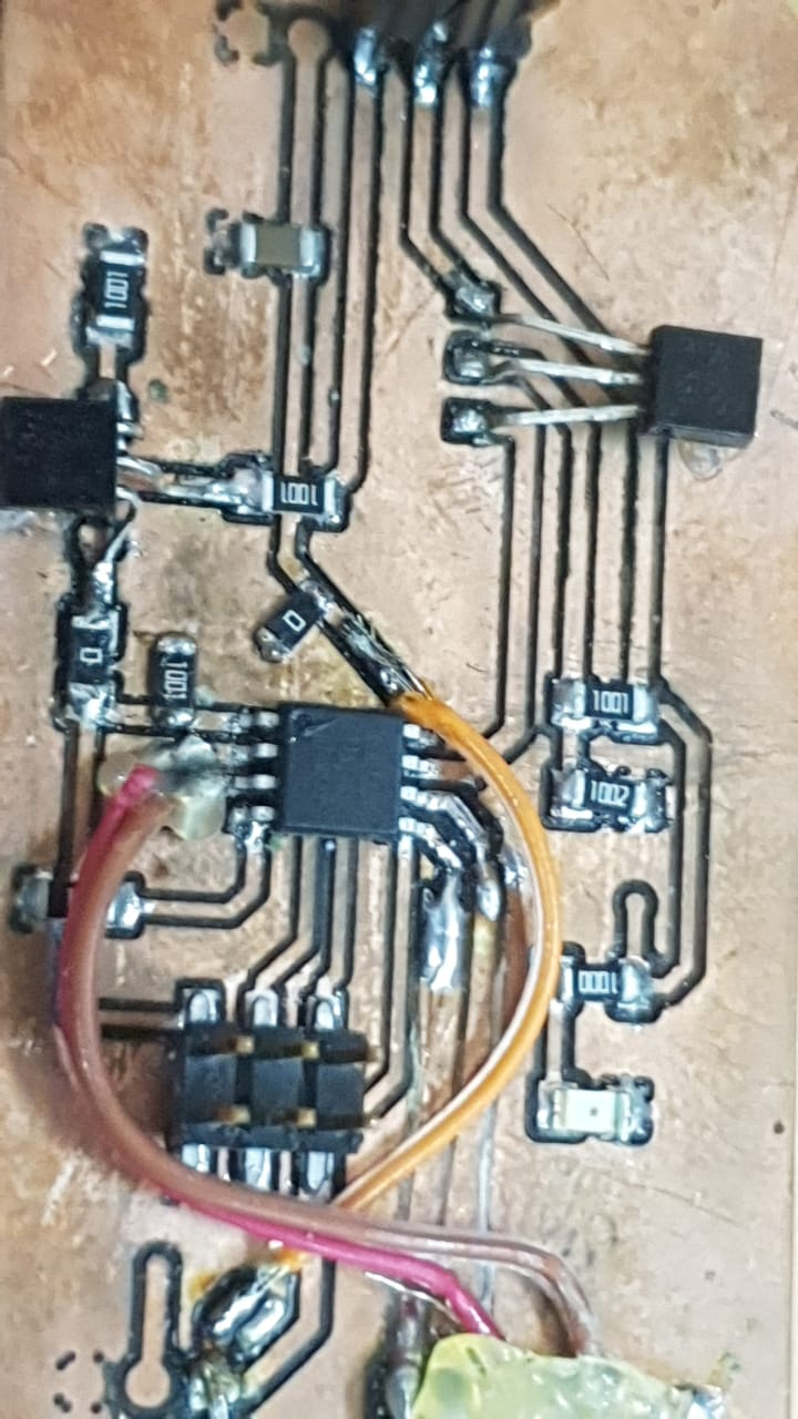
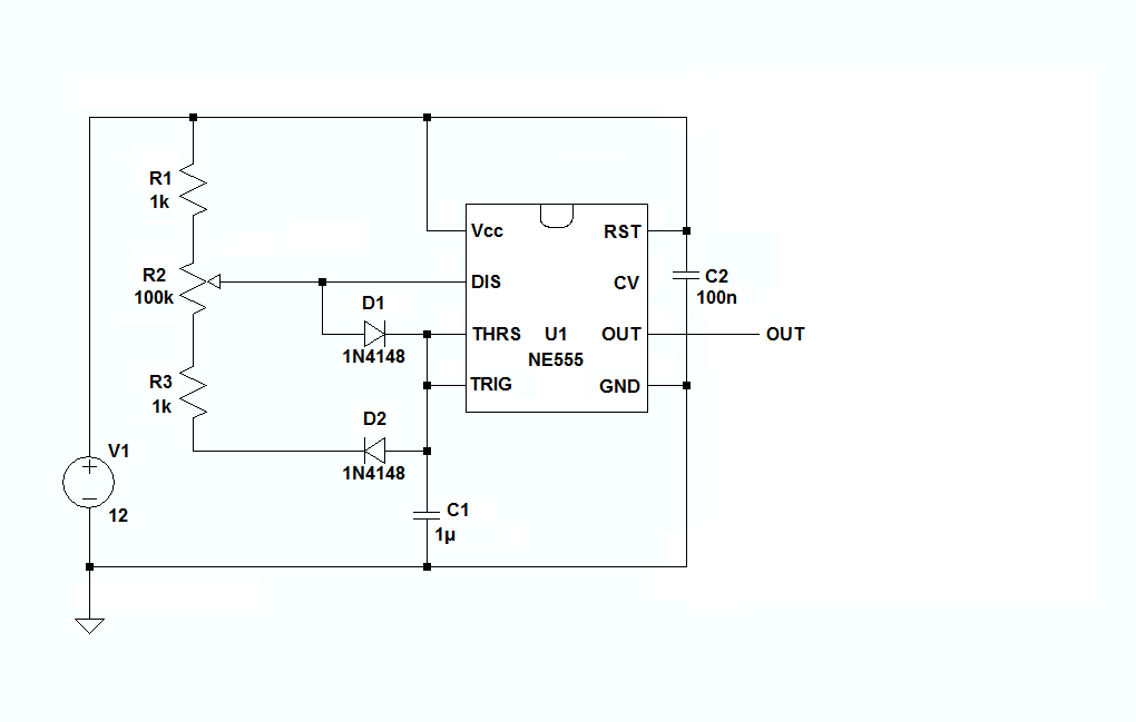
Example of simple NE555 based pulse generator design.
Since my goal was to simplify/minify the whole step-dir controller, adding more functionality really stretches the limits of the ATtiny45 by adding 2 functionalities to the already packed pin resources and wishing to add yet another one for pulse generation with an NE555 chip will be more costly than just replacing with the ATtiny44 with all wished functions on board.
Wireless networked Stepper Controller
Ultimately for my final project i want to combine these functionalities in a small size wireless networked stepper-controller-end-stopper unit that sits directly on the back-plate of a Nema17 stepper motor. This is inspired by the Jake Read networked stepper controllers.
We will add the pulse generator, the ESP Wifi chip and probably use an ATtiny44 to also run Serial communication between the ESP module and the rest of the board.
What about Synchronicity?
Only question i still have to figure out is how to keep these types of wireless driver nodes in sync in a CNC use case where motion coordination is critical.
Files & Downloads
Containing: * Board design files * Code for the step-dir controller
References
Attiny85 as a StepDir Stepper Motor Controller