Final Project
-=[ 2019-01-28 ]=-
Idea : Build a SMD/SMT component pick and place machine
Since electronics and miniaturization thereof will become more important to the Maker community i think the creation of a desktop Pick & Place (PnP) machine would benefit everybody. Hand-soldering of these tiny components is very tedious and error prone process.
For our IoT lab in Suriname i tried ordering the Cirquid CNC device for PCB prototyping, including milling of traces, applying solder paste and pick and place components. Factory answered that the unit was out of production because the linear encoders aren’t available from the source anymore so they had to stop production. So there the idea was created to work on a CNC Pick and Place machine for electronic components.
Looking at existing Pick and Place units i found they almost all run on OpenPNP platform. The simpler ones pick a single item at place it on Gcode defined positions and repeat the process until the board fully populated with components. The more advanced devices do position with multiple heads, revolver heads or a chain of heads.
Target here is to create a revolver head for multiple part pickup and delivery from a single toolhead sharing utilities like vacuum pressure and part axial rotation/calibration.
OpenPNP has all the tools for optical optimization of placement with an on-board cam and calibration of directionality of components with the bottom camera.
So i will create a simple version of this revolver system for pick and place and include 2 small size cameras connected to a Respberry Pi to feed cameras to OpenPNP/OpenCV processing.
Research
Upon the preliminary research i stubled upon the list of already available Pick and place units. The main stream of these use OpenPnP as firmware for their systems.
A few machines in the DIY space
OpenPnP OpenBuilds by OpenPnP – An OpenPnP machine reference design based on OpenBuilds linear motion hardware and 3D printed parts.
DIY Pick and Place by Teton Technology (https://hackaday.io/project/9319-diy-pick-and-place) – An Open Source DIY cartesian PnP machine using Rails / Carriages for high speed and accurate part placement.
Zeva 460 Retrofit by Daniel Dumitru – Documentation on adapting a Zeva 460 Pick and Place to use OpenPnP.
LitePlacer by Juha Kuusama – “The Low Cost Prototype Builder’s Pick and Place Machine”. To use OpenPnP software with LitePlacer hardware, see the wiki page.
QiHe TVM920 Documentation and driver for running the TVM920 with OpenPnP. All of these have their own speciality and accuracy so my challenge is to include some
Initial conclusions #low hanging fruit
After reviewing all existing Pick and Place designs available question is what to possible add to the spectrum here.
1. Decrease machine travel - Revolver head
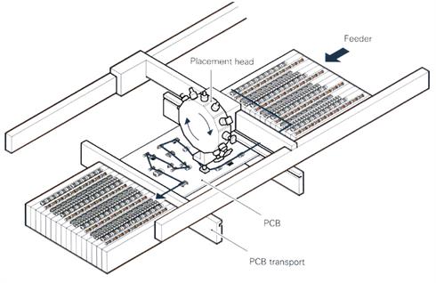
Most of the PnP systems involve a single or sometimes 2-3 heads moving back and forth between the component feeders and the workpiece. This could be optimized by adding more pick-nozzles to the system, but with the side-by-side approach we quickly run out of XYZ infrastructure. This is the main reason to try to create a revolver type head that consists of 8-12 pickup nozzles potentially of different types. The machine travels only once for pickup of 12 items and the speed of production can be increased.
During our company tour in Europe where we visited Omron’s industrial electronics plant in Den Bosch where we saw an advanced production line utilizing 2 revolver heads alternatively going between pickup zone and workpiece.
2. Increase accuracy - use Low cost XYZ frame with Optical compensation
Since most of these systems rely on either expensive linear encoders or sturdy and accurate XYZ systems i will add Optics to the equation. So initial design would be a XYZ motion platform (of potentially crappy quality) and add a camera and optical sensing to improve accuracy of placement of components and potentially QC of the final reflowed PCB.
3. Keep it light weight and fast - Nozzle re-think & re-design
The things that make the pick and place units heavy is the pneumatic actuators. Simply adding 12 of these to a revolver will only make the system less agile and even bulky. This asks for a total different design where i will try to use a common-pneumatic-rail with independently operating nozzles for the pick and place action.
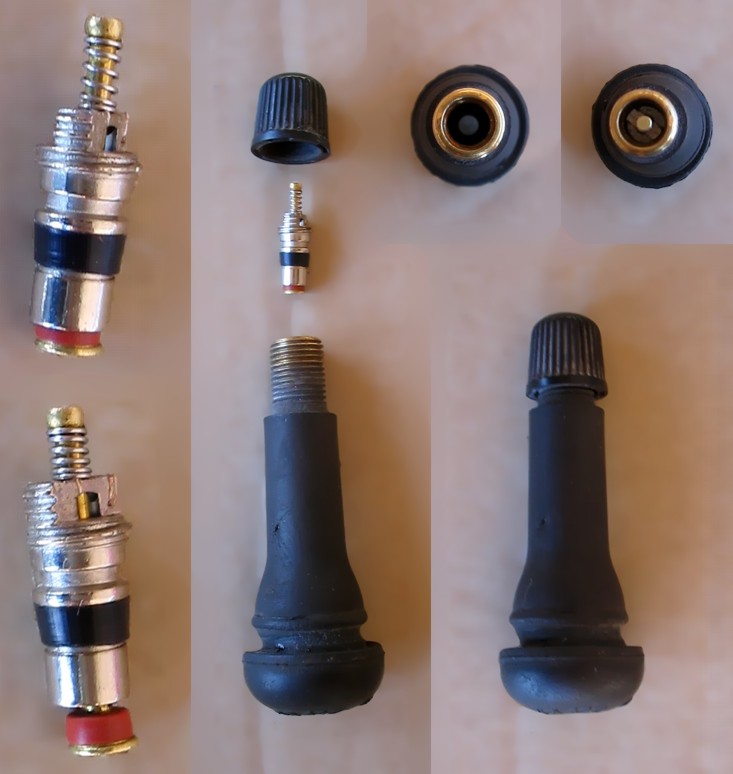
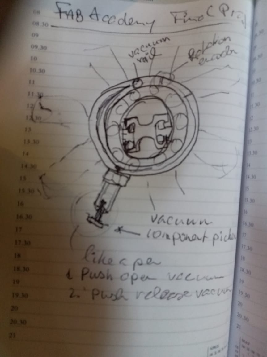
Inspired on the old “parker-pen” for the set/reset action

and the tire air-valve for maintaining suction pressure on each head during the delivery cycle.
First approach will be to add this all to a 3D printed needle-bearing with the pressur/suction rail running inside the outer bearing race.
4. So what we gonna do?
I know its a lot to chew but i will make some disclaimers on the system: 1. We focus on the Revolver head 2. as i said i dont care about the design & (to some extent) quality of the XYZ motion system itself and we will use an existing design for the frame. 2. We will use the software stack from the OpenPNP group and build only the compatible CNC driver boards.
The system architecture
A Pick & Place system consists of many aspects so building a full end-to-end system is too big of a project for this short period.
The main components of my project in order of importance
- Revolver head with component pickers for SMD components pickup and placement on the workpiece
- Processing unit (Ubuntu laptop)
- The YX(Z) motion system for moving around the rotary head on pickup (based on commercial control board)
Supporting sub-systems for proper operation of PnP
- Bottom camera /light box for calibration of components in the nozzles
- Top camera system for workpiece calibration and component positioning moves with the gantry and requires an off-set parameter to be set
- SMD component feeders & trays (i don’t have these available here)
So thr main focus is on the revolver head that hosts the pickup nozzles and runs as an independent sub-system in the whole Pick and Place environment.
Receiving gcode commands for rotate, nozzle select and pick or discharge of components.
It is wirelessly connected to the OpenPNP system and responds only to specific G-codes thereby disregarding position or other instructions.
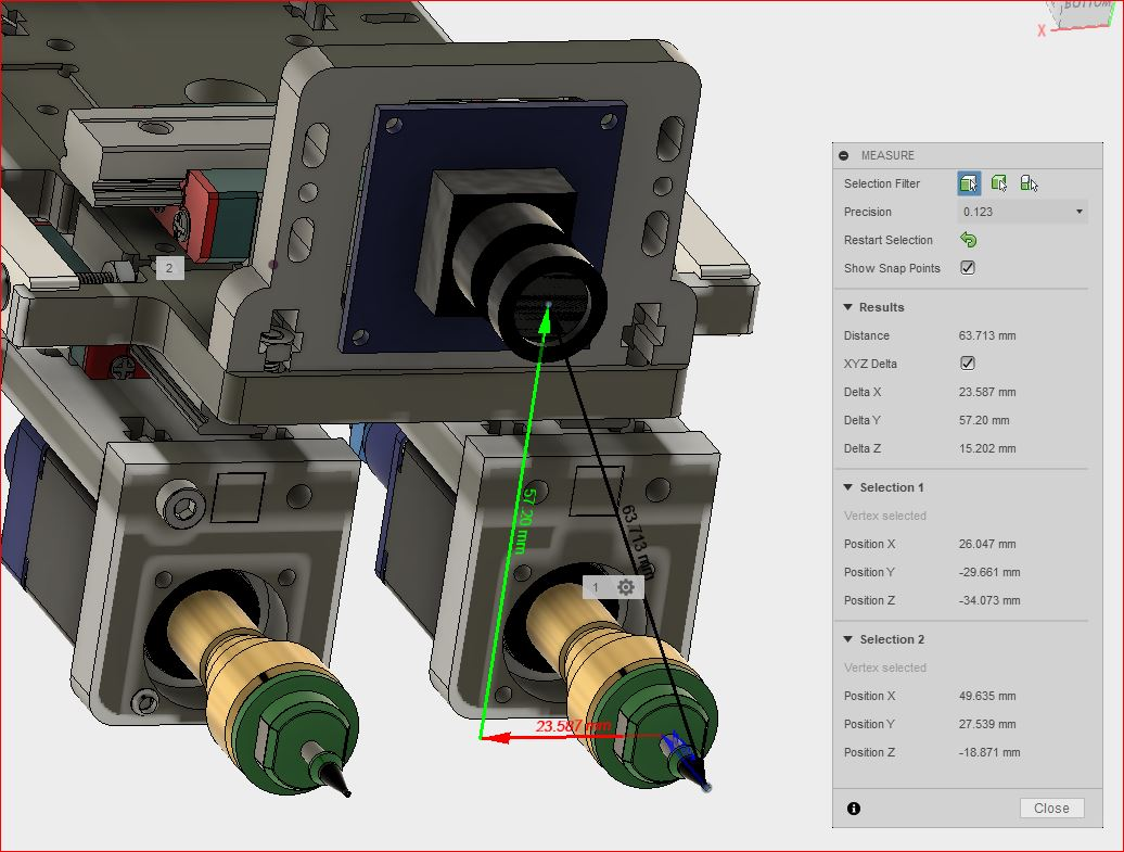
Proof of concept
For proof of concept i will show the mechanics of the revolver head operational doing Revolver Rotation (tool change or select nozzle command), Nozzle rotation (Parts positioning/calibration) and the Punch Action pushing the nozzles downwards (component pickup and placement).
Parts & Materials required
| Qty | Description | Price | Link | Notes |
|---|---|---|---|---|
| 3 | T-slot extruded aluminium | -.00 $ | stock | |
| 2 | NEMA17 (X-Y) | 12.00 $ | ||
| 1 | NEMA8 (Rotation) | 15.00 $ | http://amazon.com/test | |
| 1 | NEMA? (Z) | 15.00 $ | http://amazon.com/test | |
| 1 | CNC-frame joints | 20.00 $ | http://amazon.com/test | |
| 1 | Belt & pully’s | 15.00 $ | http://amazon.com/test | |
| 1 | other materials | 20.00 $ | http://amazon.com/test |
Needs to be expanded!
The mechanical build
XYZ chassis
For the machine and motion frame i got inspired by the INNRDrive & OpenRail concepts where the belts, pulleys and motors are all constructed inside/around a V-slot extruded aluminium frame. I found some T-slots in my storage and decided to use those for the final project instead. This needed some adjustments to the standard OpenSlide, Openrail designs (the wheels just sit abit higher on the rails).
ToDo: Foto comparing V-slot and T-Slot
With this little adjustment all the standard gantries and caddies could be used from the above systems.
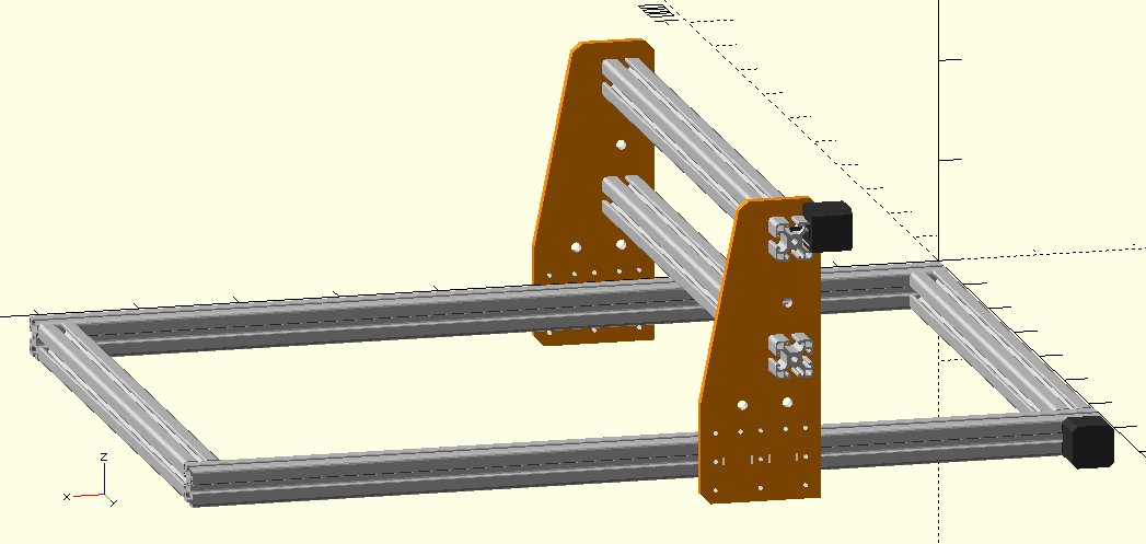
I made the T-slot cross section in LibreCad and exported it to DXF. In OpenSCAD i made a parameterized model of the whole motion system.
Parameters to the system are the size of the frame (LWH) the beam size and the position of the Y-gantry for display or simulation.
// XYZ system parameters


frame=[690, 910, 270]; // frame XYZ


beam=[40, 40]; // beam size XY


xpos= 910/3; // Position of the X-gantry
After this I generated a baseline for how i want the gantry to look like in LibreCAD and exported the contours to OpenSCAD as dxf.
Initially i already added the openings for beams and wheel axles on the dxf drawing in Librecad but this was a bad choice.
You really want to do that all the cuts and adjustments parametric by cutting these things out based on your beam-size and frame dimensions.
Initially a bit fiddly and non scientific approach but this design is fully parametric now and i created holes for multi use of this XYZ system.
I was inspired by the Stepcraft CNC in our lab and worked with that as baseline. Added holes for potentially 6 wheels, spindle or guide in the middle between lewer and higher beam setup. Also added Nema17 stepper footprint for adding a stepper on the gantry itself instead of on the T-slot beam.
This system will probably serve as test-bed for my first waterjet by sliding out the base board and adding a water tank underneath it.
The full XYZ system mockup
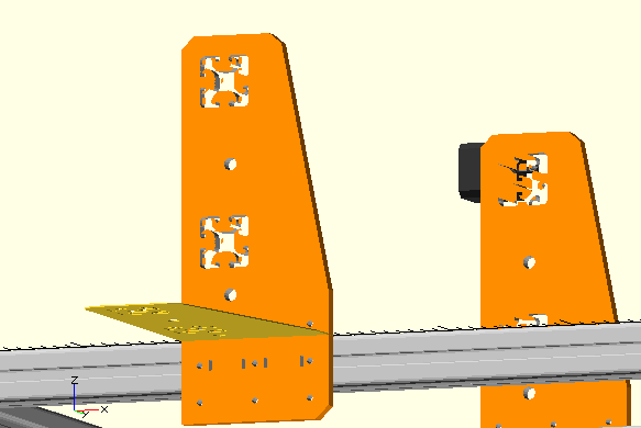
Setup a projection layer for the gantry gives a 2D projection of the gantry ready for exporting to dxf format for laser cutting or milling. You will have to hide all other objects to be able to render it into 2D vectors SVG or DXF file.
// CAM projection side panels Y Gantry mockup


projection(cut = false) rotate([90,0,0]){


ygantry(10,[xpos-0.5*beam[1],0,-1.5*beam[1]],[90,0,0]);


}
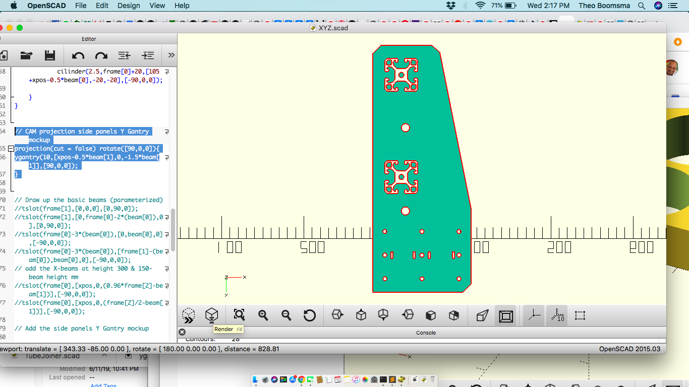
Export the file to dxf format and import in Visicut and generate gcode file
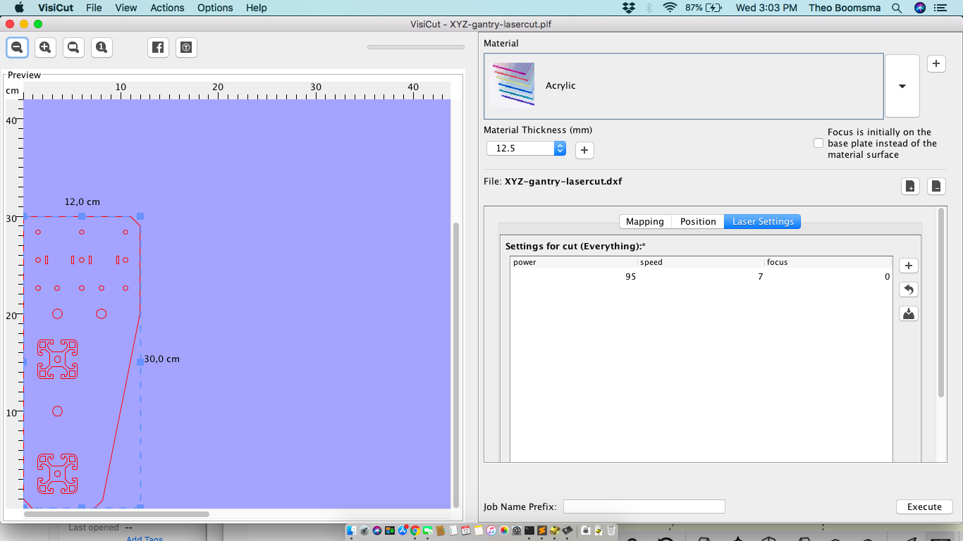
The gantry panels were laser cut from Acrylic and another set was CNC cut.
XYZ Assembly
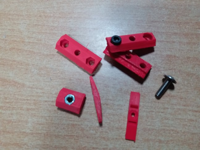
For frame fittings i 3D printed T-slot locks
We build the X-beam & gantry first for testing motion & control with a Ramps1.4 controller. For time constraints i will do this part with existing controller. The proof of proficiency in electronics design i will leave for the Revolver Head controller.
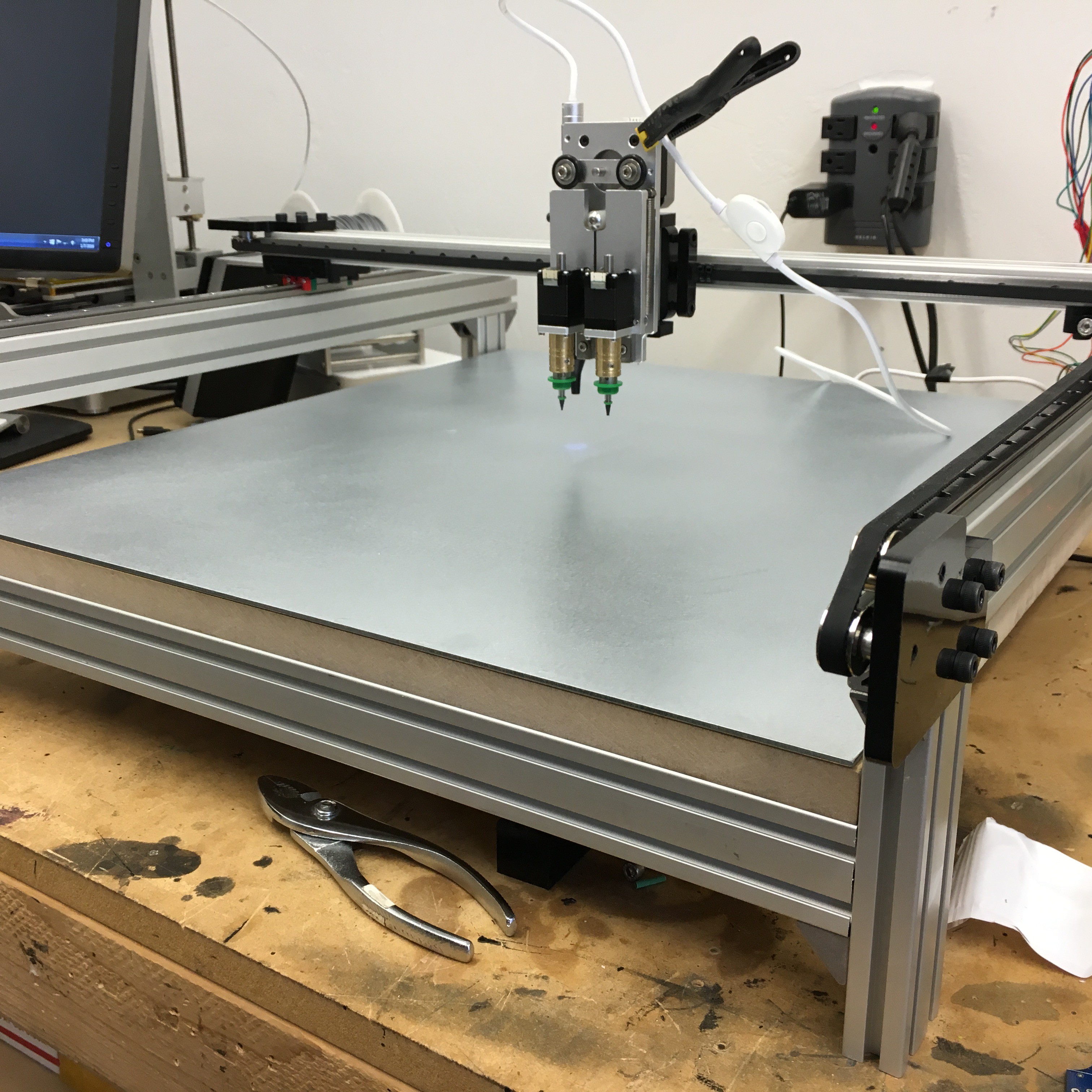
The complete XYZ assembly
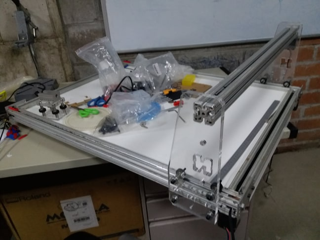
Ramps1.4 controller & nema 17 steppers connected we run some tests for speed
References:
-
Compact 8020 T-slot linear drive called INNRDrive
Revolver nozzle holder
The idea behind the nozzle holder rotor is to host a set of 12 standard (Juki) nozzles to reduce travel between pick zone and workpiece. Compared to the standard way of doing it with single actuators this imposes a few challenges
- Nozzle vacuum must be shared/connected to the whole set of nozzles so the delivery of vacuum
- Nozzles should be able to rotate at least a full 180 degrees to change orientation
- An actuator on the revolver caddy should deliver the “punch down” for the component pickup and place actions and allow for enough flight height (normal free flight is at ??? mm). Preferrable we should do this all without the need for Z-axis movement.
- Nozzle rotor should be placed on an XY(Z) system of standard extruded aluminium
- The whole revolver system should operate as autonomous as possible with only 12V power delivered to it (my choice).
Pick n place Nozzles
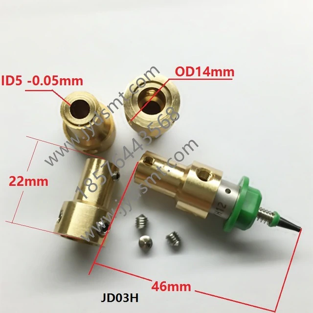
I found a CAD file of the Juki Nozzle to print ASAP for mockup and my reference. I actually till today never seen or touched one myself.
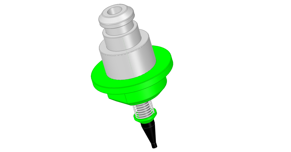
Basic Nozzle dimensions( Juki Nozzles)
DIY Nozzle holder i can use as a design reference
Juki nozzle applications catalog
Vacuum pressure
Vacuum suction is essential for PnP operation. THis also imposes the most restictive constraints to these systems. The vacuum has to be delivered all the way to the nozzles for pickup and cut off for component drop off.
You want to keep it closest to the nozzles as possible
An on-board Vacuum pump system
Miniaturization is the key here whilst keeping enough suction and here an Interesting vacuum pump discussion
Vacuum pressure sensing OpenPNP
Vacuum delivery
The vacuum will be deliverd to each nozzle via the pressure ring inside the outer ring of the revolver.
We have a vacuum line inside the outer ring and all we need is some rotary joint system to provision vacuum to the nozzles.
https://us.misumi-ec.com/vona2/detail/110300339870/?Inch=0
The rotor initial design
Design implications
- Shared vacuum delivery preferrably on board (of the caddy).
- Get the vacuum into the rotator enclosure
- Shared nozzle rotation motor to calibrate picked components
The baseline:
We needed some sort of beveled gear to enable rotation of the nozzles from a shared source.
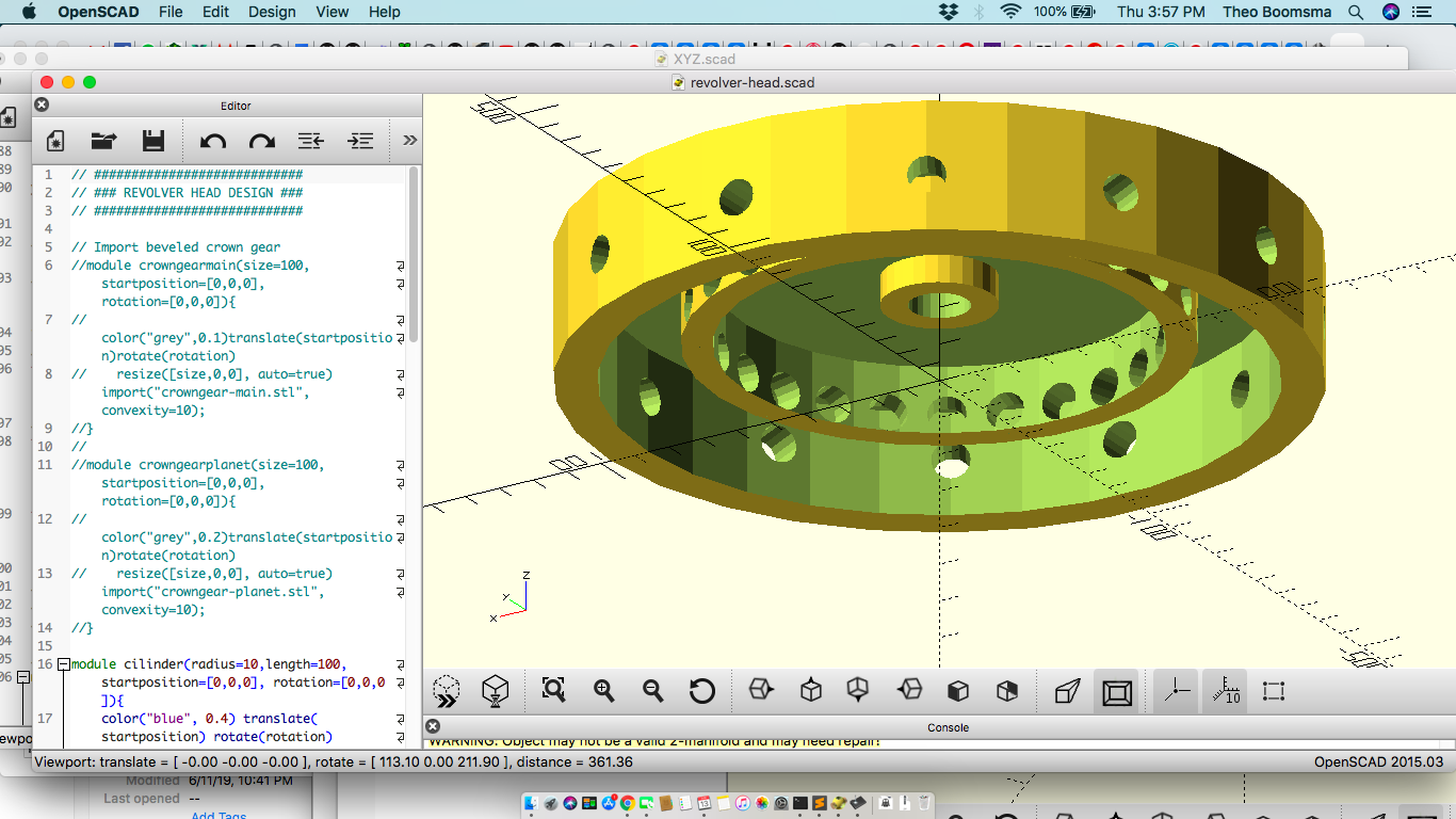
I
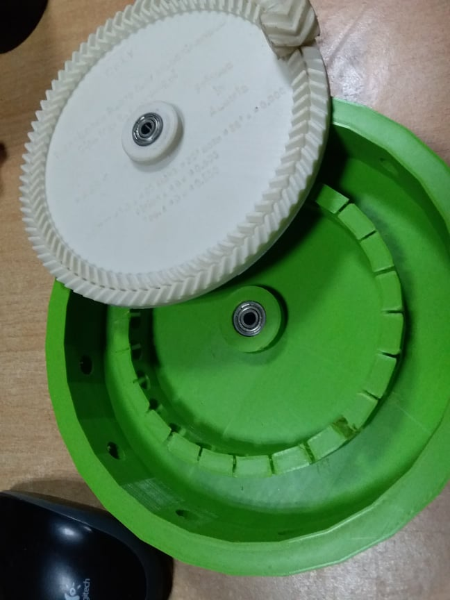
found an interesting looking beveled crown gear actually just because it looked cool and created a housing for it..
Update:
During the implementation later this choice we obviously the worst choice i could have made.
The gear rotates only in one direction easily and is extremely sensitive to positional inaccuracies of the planet gears. When joining 2 bodies into a single assembly this becomes a serious issue.
We had to redo these gears completely under all the stress of Fab Academy closing.
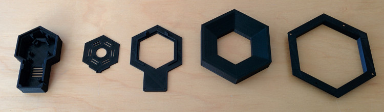
Import the base gear and planet gear and build the surrounding outer ring that will hold the nozzles
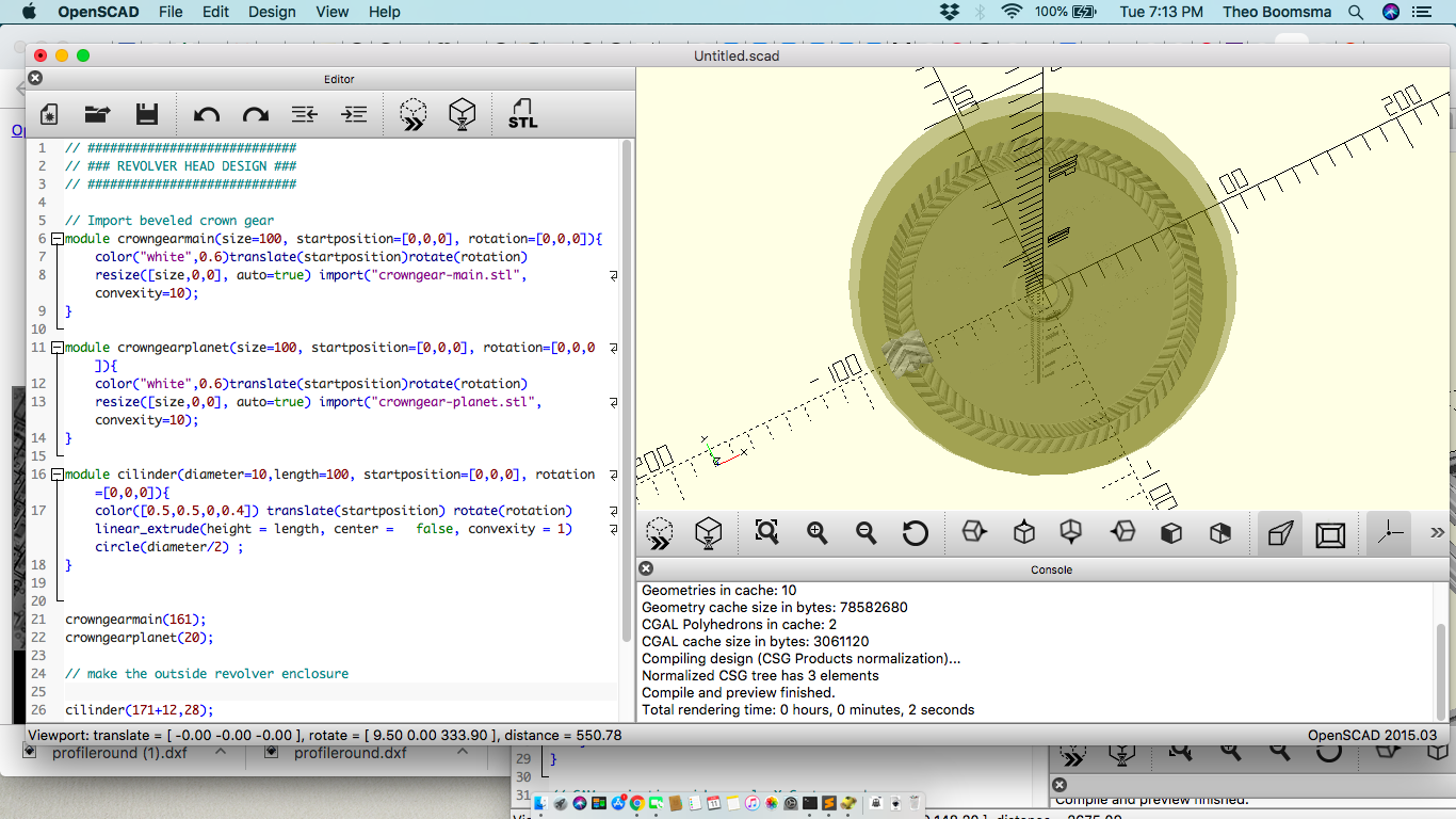
Carve out the middle and make the flange to connect to the
The revolver outer enclosure
After this we create the outer enclosure that will host the gear providing holes for passing gear shafts to the nozzles outside of the ring.
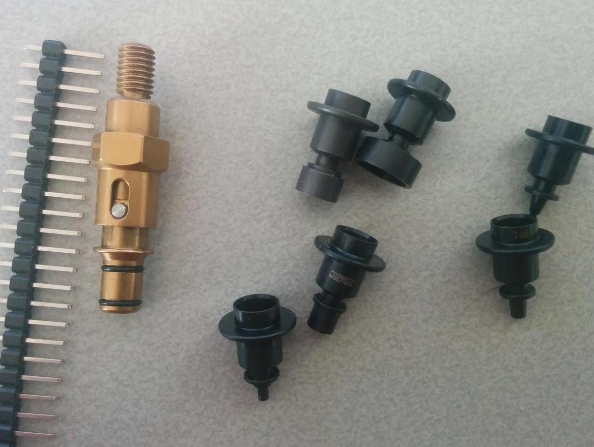
These nozzles are connected to air system via slip-couplers
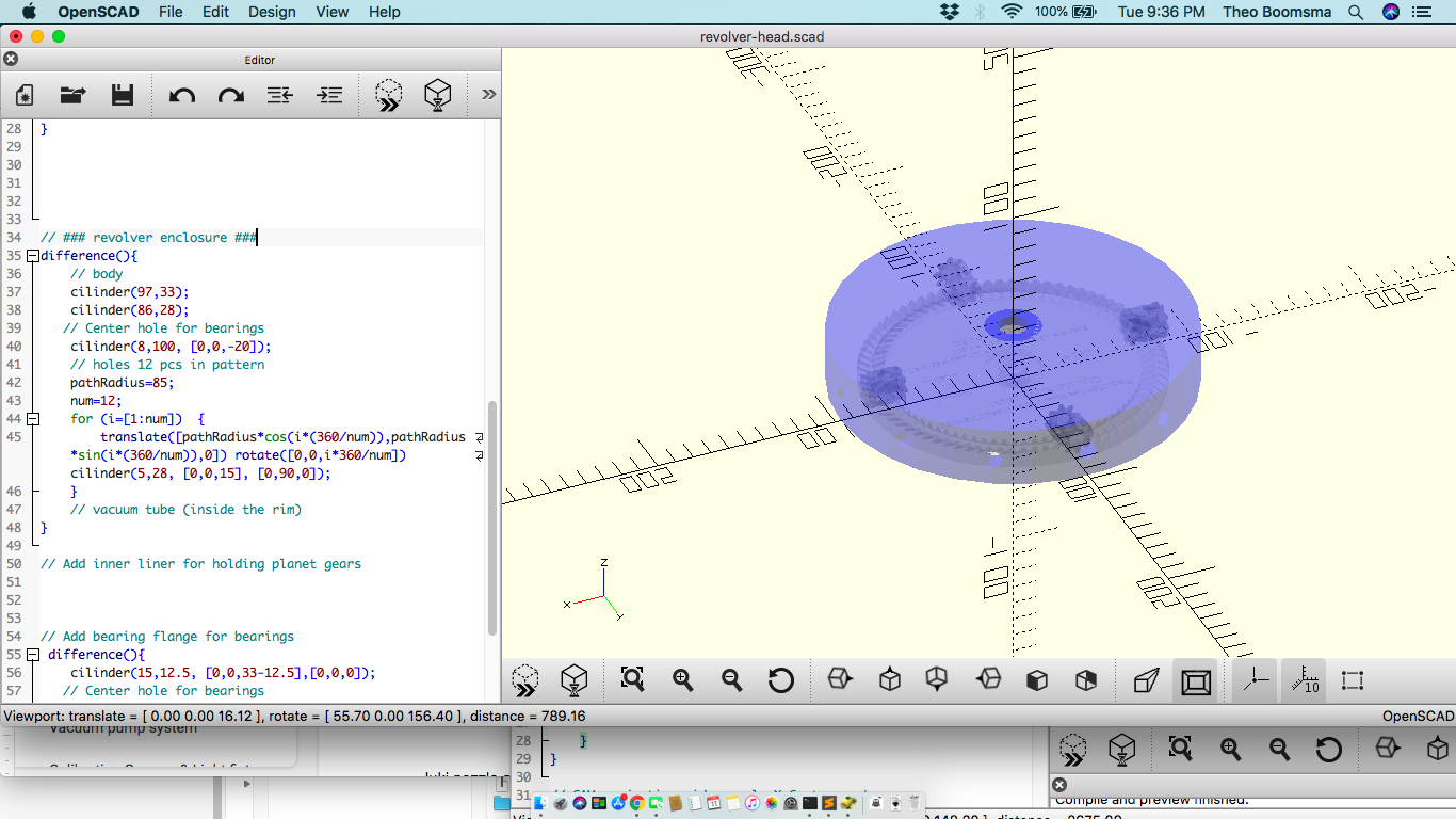
The planet gears will need some extra support on the inside end so i create an ring for that. With that ofcourse limiting the accessibility inside the assembly. I will double the amount of holes there so each planet gear comes with an extra utility hole (making it 24 holes total)
On the outside of the housing the main gear for rotation of the revolver will be hosted by means of an involute gear (inner-gear ring) 130 mm diameter 37 teeth and the runner will be driven by a small stepper motor sitting on the caddy. The stepper was sourced from CD-Rom player and has stepper motor with 40mm diameter 11 teeth gear. We worked a bit backwards on this upcycling an old aluminium slider mechanism as base frame so we had to fit things to space.
Luckily everything fit nicely.
For the sake of progress and time management i printed this gear separate from the revolver enclosure and glued it on afterwards. But the idea is this should be integrally 3D printed.
The actuators
For driving all functionalities on the Revolver head we will need 3 actuators and a vacuum pump on board.
- Main motor will be a stepper motor driving the Revolver Rotation via the Involute Gear
- Nozzle rotation motor will be a small CD-Rom motor to enable parts calibration and rotation on the workpiece
- Punch motor will be a 20kg servo that will move the whole rotor assembly down to pickup and place the components
- Vacuum pump will deliver vacuum to the nozzles connected via vacuum rail.
Smart nozzle holder
For switching on and off vacuum on the nozzles most pnp machines come with vacuum switches, one per nozzle. Of course this would NOTwork for our design as carrying all these switches on the revolver would make it too bulky.
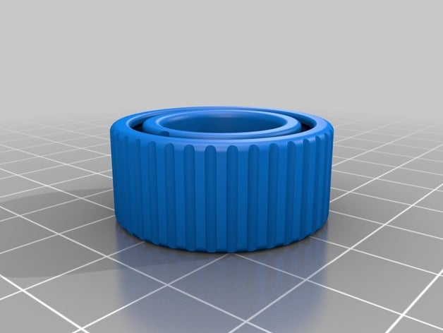
We redesigned a special nozzle holder that is always on vacuum in set mode and releases vacuum in unset mode. This is mechanically imposed set/reset action inspired on the old parker pen principle.
Here is an example of the Pen-lock mechanism that serves as inspiration.
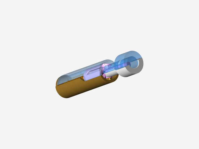
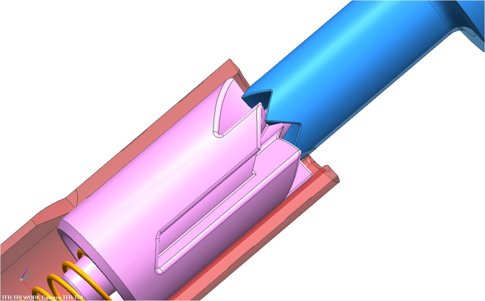
This lock will activate and deactivate the vacuum pressure on the connected nozzle.
Enclosures
Any system will need a full set of enclosures so as such we will have to create some for
- XYZ system is build on with a Ramps1.4 + Arduino Nano main board
- The Ramps pendant
- The Revolver controller board (ESP32 board)
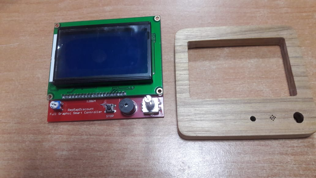
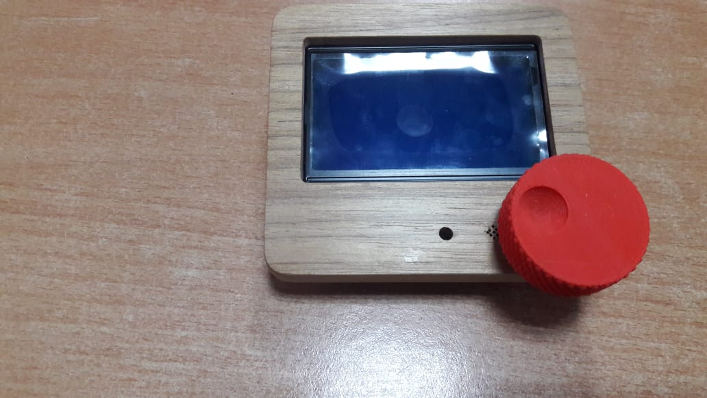
Enclosure for the pendant is a mixin between 3D printed back + a polished wooden front panel with a bigger button on it.
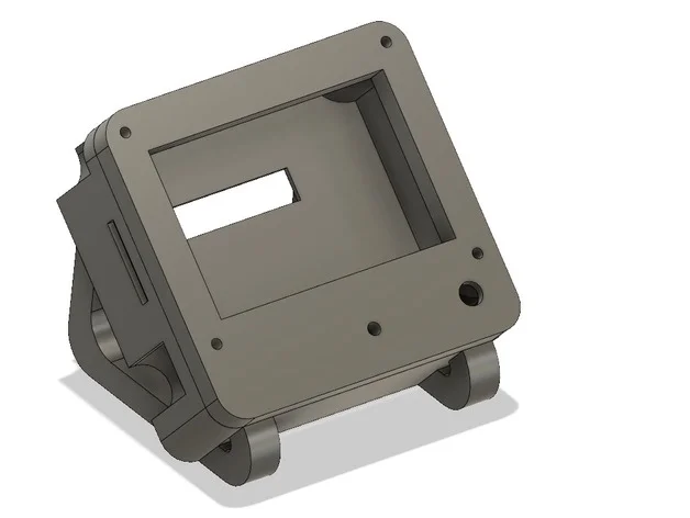
The front from wood by glueing 2 layers together.
The inner has some pockets for fitting electronics etc.
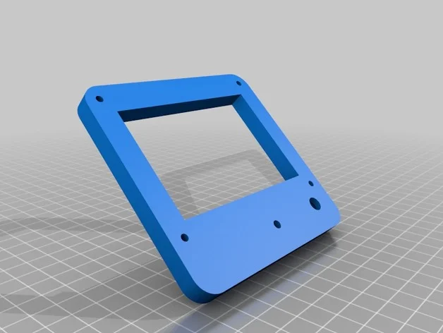
Export the STL to TinkerCAD rotate to be flat and export SVG file and after that import into MakerCAM for CAM & gcode generation.
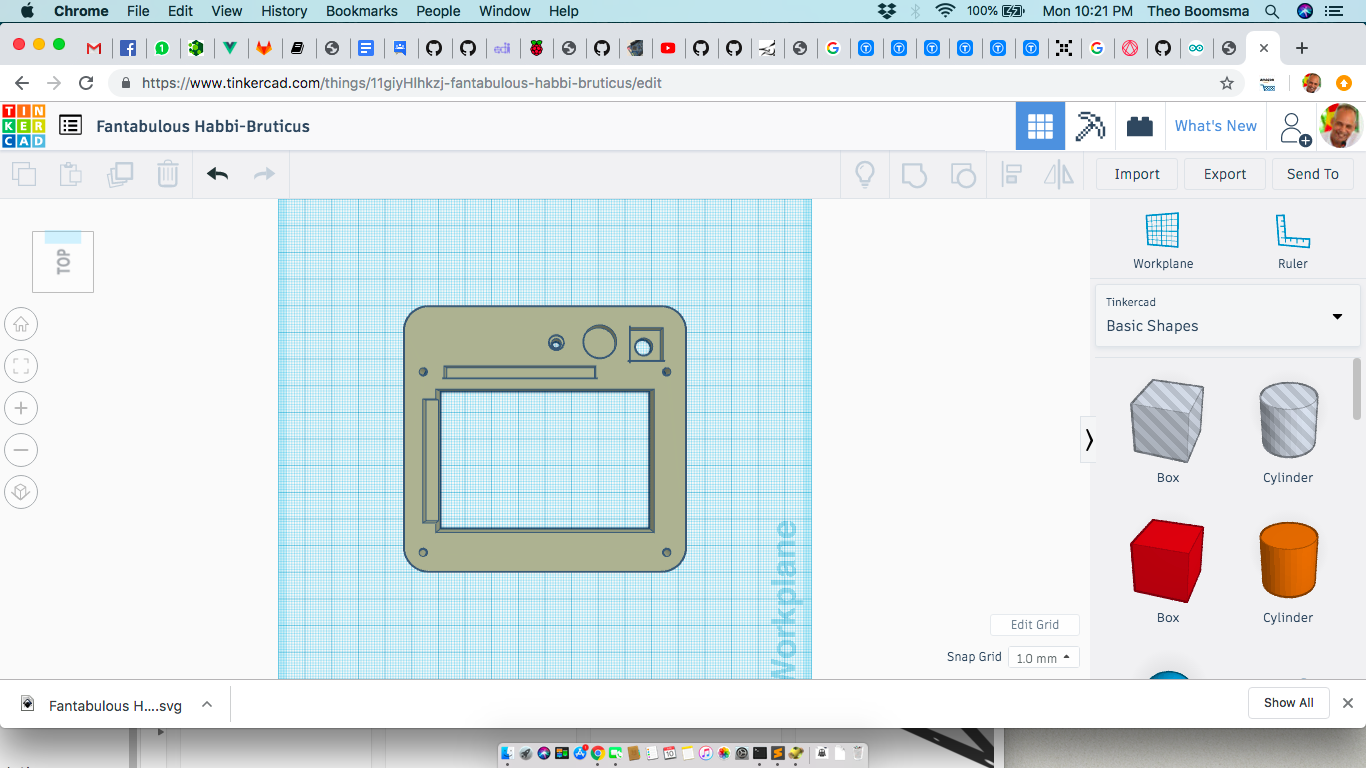
Unfortunately the details of all the pockets that we would incorporate in the 1st panel are not exported to SVG so we cannot CNC those cuts. The Model could NOT be ingrouped by TinkerCAD. We just went ahead with what we had for now and hand-carved the pockets where needed with a dremel since it is on the inside of the enclosure anyway.
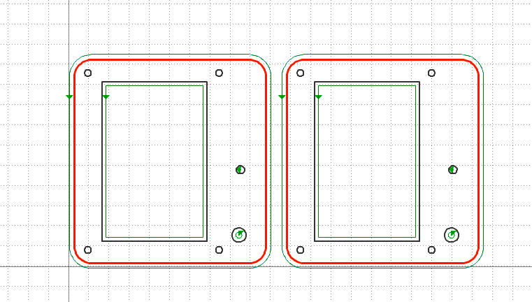
Cut out on the Stepcraft CNC
Ramps System board enclosure
The system board hosts both the RAMPS board and the RaspberyPi hosting the video streams.
It is placed in seperate box as we plan to use the unit also as a prototyping platform for CNC and WaterJetting we dicided to place them in an external box with sturdy industrial connectors
Note: For time constraints we skipped this for now!!
The Revolver controller enclosure
To do!
Calibration Camera & Light fixtures
Out of scope but necessary to mention also. As a future project i would like to develop en add in OpenPNP board that one could simply add to an existing CNC machine and have all needed support services ready.
Component Feeder
The component feeder is an essential part of the PnP system. It makes sure the components are delivered to the pickup zone consistently and as accurate position as possible.
Unfortunately i dont have any feeder available nor the time at hand to build one now.
Ofcourse we will need to build this functionality too around our pick an placer.
But there are plenty of DIY projects around to build them later on
http://www.knasmusic.com/diyeverything/pickandplace/tapefeeders.php
Discussion
https://www.liteplacer.com/phpBB/viewtopic.php?f=11&t=191&start=20#p1297
Bevel gear straight / spiral
https://www.thingiverse.com/thing:957564
https://www.thingiverse.com/thing:961943
Bottom camera
The bottom camera for calibrating nozzles & component orientations
Heres a great example ready to print and implement
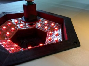
Source: http://malte-randt.de/3d-printable-camera-mount-for-liteplacer-pp-machine/
In-flight camera
Typically attached to the nozzle system that controls placement on the workpiece
Should be added for more accurate component placements
Video streams to OpenPNP
To setup video streams into OpenPNP system i will try to implement two options.
- Simplest is the Raspberry MJPEG streamer
MJPEG-Streamer install https://cnc.js.org/docs/rpi-setup-guide/
    # Clone Repo in /tmp
    cd /tmp
    git clone https://github.com/jacksonliam/mjpg-streamer.git
    cd mjpg-streamer/mjpg-streamer-experimental
    make
    sudo make install
    /usr/local/bin/mjpg_streamer -i "input_uvc.so -r 1280x720 -d /dev/video0 -f 10 -q 80" -o "output_http.so -p 8081 -w /usr/local/share/mjpg-streamer/www"
MJPEG-Streamer Dual stream on Raspberry Pi 3 (here)
/usr/local/bin/mjpg_streamer -i "/usr/local/lib/mjpg-streamer/input_uvc.so -n -f 10 -r 1280x720" -o "/usr/local/lib/mjpg-streamer/output_http.so -p 8085 -w /usr/local/share/mjpg-streamer/www"
- Direct analog over wireless camera streams as used on drones ( i happen to have one available so its worth the try)
Embedded controller & OpenPNP software
Since i used the Ramps 4.1 board for XYZ system we will go with the Marlin version specifically for OpenPNP found here .
The revolver head gets his own independant controller that listens to:
- tool switch (identical to OpenPNP with multiple heads)
- component pickup and drop-off commands
- Component calibrate/rotate
- tool change commands to pickup new tools
Links & References
The build story line example
https://mcuoneclipse.com/2018/06/26/building-a-diy-smt-pickplace-machine-with-openpnp/
BrdMaker (high accuracy DIY system) \ https://hackaday.io/project/22033-brdmaker
https://hackaday.io/project/9319-diy-pick-and-place
OpenPLacer Manual
http://www.openplacer.com/wp-content/uploads/2018/08/setup-and-calibration.pdf
http://citeseerx.ist.psu.edu/viewdoc/download?doi=10.1.1.486.8305&rep=rep1&type=pdf
https://link.springer.com/article/10.1007/s40903-017-0070-4
Purchase toolchanger Nozzles or
https://www.robotdigg.com/product/467/NOZZLEs+503+504+505+506+for+SMT+Machine
Jake Read - Wireless & Parametric machine designs http://www.openassemblies.com/
Jake Read - Motor Controller https://gitlab.cba.mit.edu/squidworks/daughterboard-stepper
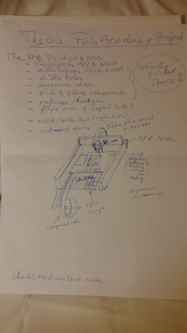
Sketch for Final project
https://www.youtube.com/watch?v=kSqpdPrJAqg
Pick n Place DIY https://www.youtube.com/watch?v=cN1iHxsST_A
SMT loader/dispenser https://www.youtube.com/watch?v=XuHYhp0ltME
DIY Pick n Place Nozzle https://www.youtube.com/watch?v=SMetmhIzcPY
Purchase toolchanger Nozzles http://www.nozzles4smt.com/Lightning-125-Compliant-0125-3220_p_1370.html
Needle bearing OpenScad https://www.thingiverse.com/thing:2162376
Jake Read - Wireless & Parametric machine designs http://www.openassemblies.com/
NanoTec Stepper selector https://en.nanotec.com/products/2263-hybrid-stepper-motors/
Nice CNC router design https://grabcad.com/library/another-cnc-router-2
Minion-CNC / Kids educational https://www.thingiverse.com/thing:1133290
Fully 3D printed Pick And Place machine https://www.thingiverse.com/thing:1001590
Rotary encoder using Harddrive motor + UNO https://www.youtube.com/watch?v=tjCJ3MlFt7g
Example build OpenPNP machine Example build https://groups.google.com/forum/#!topic/openpnp/w46THEk0Mjc%5B1-25%5D
/////////////////////// OLD FILE /////////
2D and 3D Modeling
Initial design sketches
PnP Revolver head design
Build Ingredients
Needle bearing for OpenScad
Compact 8020 T-slot linear drive

Nozzles

Gallery of inspiration

Videos
INNRDrive