Assignments
- Measure something: add a sensor to a microcontroller board
Subject
I try to make a basic capacitive sensor because I think it could be a useful alternative of soil moisture sensor. I need this for my final project to measure the soil moisture.
First experiments with the hello echo board
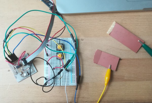
Before creating a new PCB for this week I wanted to test several methods on the hello echo board made during week 7. For these methods I need 2 pins (one to send and one to receive) and i also need 2 pins (Rx and Tx) for the serial communication. Unfortunately, I did not anticipate the use of the available pins of the ATtiny44 when I designed the circuit of my hello echo board. To fix it, i added jumpers between the pins 2 et 3 of the ATtiny44 and the available pins of the FTDI header.
| BOARD | JUMPERS |
|---|---|
 |
 |
First test with the CapacitiveSensor library
First i try to use the CapacitiveSensor library.
Principle
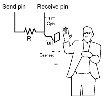
I found useful informations on the arduino playground site and how works the library: “The capacitiveSensor method toggles a microcontroller send pin to a new state and then waits for the receive pin to change to the same state as the send pin. A variable is incremented inside a while loop to time the receive pin’s state change. The method then reports the variable’s value, which is in arbitrary units.“
To work the circuit is composed of 2 pins, one to send a signal and one to read, and a high value resistor between them.
Programming
I tried this Arduino code:
#include <CapacitiveSensor.h>
#include <SoftwareSerial.h>
CapacitiveSensor   cs_3_2 = CapacitiveSensor(3,2);        // 10M resistor between pins 4 & 2, pin 2 is sensor pin, add a wire and or foil if desired
SoftwareSerial mySerial(0, 1); // RX, TX

void setup()
{
   cs_3_2.set_CS_AutocaL_Millis(0xFFFFFFFF);     // turn off autocalibrate on channel 1 - just as an example
     mySerial.begin(9600);
}

void loop()
{
    long start = millis();
    long total1 =  cs_3_2.capacitiveSensor(30);


    mySerial.print(millis() - start);        // check on performance in milliseconds
    mySerial.print("\t");                    // tab character for debug windown spacing

    mySerial.println(total1);                  // print sensor output 1


    delay(100);                             // arbitrary delay to limit data to serial port
}
But i received this error:
Archiving built core (caching) in: /var/folders/t8/khjsd06s51dflqlm2wn6hjwr0000gn/T/arduino_cache_87601/core/core_attiny_avr_ATtinyX4_cpu_attiny44,clock_external20_51f02b7210b938436b779d1c032618e1.a
Le croquis utilise 4362 octets (106%) de l espace de stockage de programmes. Le maximum est de 4096 octets.

Les variables globales utilisent 162 octets (63%) de mémoire dynamique, ce qui laisse 94 octets pour les variables locales. Le maximum est de 256 octets.
Croquis trop gros ; vois http://www.arduino.cc/en/Guide/Troubleshooting#size pour des conseils de réduction.
Erreur de compilation pour la carte ATtiny24/44/84
The sketch uses too much bytes of the available storage of the ATtiny44. This is can be explained by the use of 2 libraries: SoftwareSerial and CapacitiveSensor.
Try to fix…
Older version of CapacitiveSensor library
First i tried to change the version of the CapacitiveSensor library. For my first test I used the CapacitiveSensor version 05 which supports the non-AVR board. As my board is an AVR I don’t need this last version and I used the CapacitiveSensor04.
How to replace Arduino library
Find the Arduino library folder (for Mac: Documents/Arduino/libraries) Remove the folder of the concerned library Add the new library using Arduino from zip file (>sketch menu>include library>from zip)
Archiving built core (caching) in: /var/folders/t8/khjsd06s51dflqlm2wn6hjwr0000gn/T/arduino_cache_87601/core/core_attiny_avr_ATtinyX4_cpu_attiny44,clock_external20_51f02b7210b938436b779d1c032618e1.a
Le croquis utilise 4157 octets (101%) de l espace de stockage de programmes. Le maximum est de 4096 octets.
This reduced the size of my sketch, but not enough… 101% of the available storage of the ATtiny44!
CapacitiveSensor Library modification
I found this pull request about variables types on github.
I edited the CapacitiveSensor.cpp and the CapacitiveSensor.h as suggested. Unfortunately i received an error about variable type… So I decided to look on the SoftwareSerial library.
Alternative to SoftwareSerial Library
The last option I explored was to find an alternative to the SoftwareSerial library, I looked for something lighter. I found interesting informations about serial communication with ATtiny.
Not being able to operate any of the proposed methods, I abandoned this track.
Second test from the hello.txrx.45.c Neil’s code
During week 11 review I presented the problems encountered with the size of the libraries to make a capacitive circuit. Neil advised me not to use a library and to use the step response method.
Principle
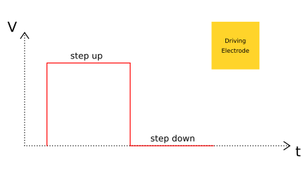
The principle consists of measuring the capacitance between two electrodes: a charging electrode which sends successively steps up and down, and a receiving electrode connected to a voltage divider which measures the received signals.
| Signal from the driving electrode | Signal received on the receiving electrode |
|---|---|
 |
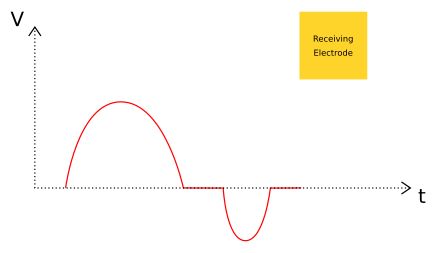 |
The difference between the sent signal and the received signal is because of the electric noise. So, to reduce this noise, the method consists to measure up and measure down and to add these values to subtract the electric noise. Then we repeat this many time.
Circuit
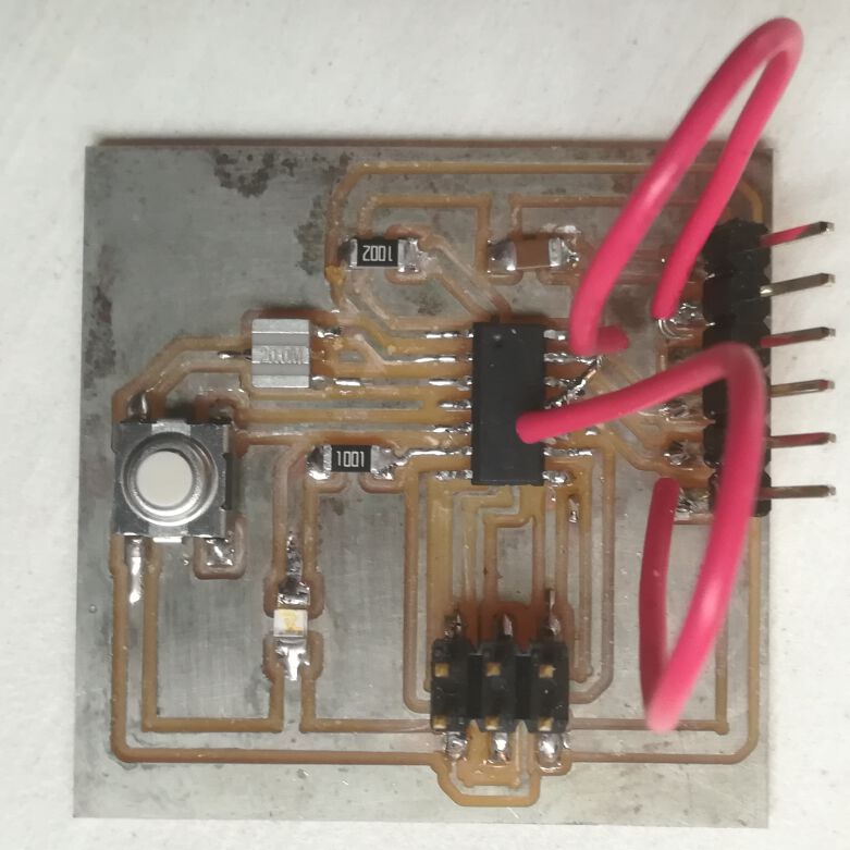
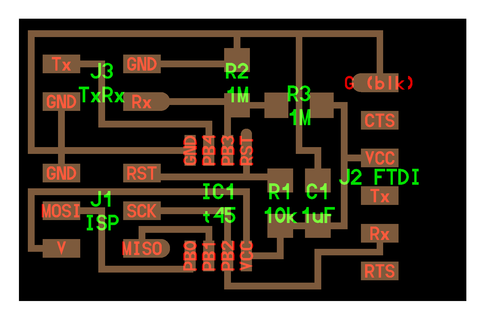
For this method Neil uses an ATTiny 45 and makes this board:
I wanted to try this method on my hello echo board that has an ATTiny44 and not an ATTiny45. Here is what connections I made:
| Connections for ATTiny45 | Connections for ATTiny44 |
|---|---|
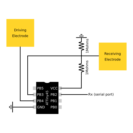 |
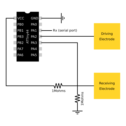 |
Programming
Not knowing the C ++ language at all I spent some time and made several changes before finding the ones that allowed me to transpose Neil’s code for my circuit using the ATTiny44. To find the solution I was inspired by these explanations about registers and channels (french). Then I compared the datasheets of the ATTiny44 with that of the ATTiny45.
Register
I modified the ports, pins and directions according to the diagram of connections presented above. To find out how modified it I looked at the register summary tables of the ATTiny45 (page 199) and ATTiny44 (page 266).
Change lines (33 to 38) of the hello.txrx.45.c code made by Neil: - initial for the ATTiny45
#define serial_port PORTB
#define serial_direction DDRB
#define serial_pin_out (1 << PB2)
#define transmit_port PORTB
#define transmit_direction DDRB
#define transmit_pin (1 << PB4)
- modified for the ATTiny44
#define serial_port PORTA
#define serial_direction DDRA
#define serial_pin_out (1 << PA1)
#define transmit_port PORTA
#define transmit_direction DDRA
#define transmit_pin (1 << PA2)
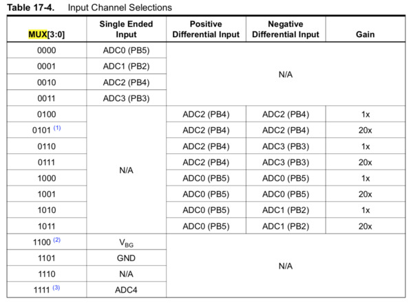
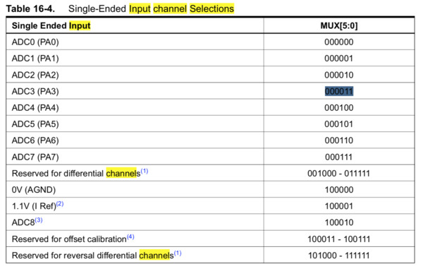
Input channel selections
| ATTiny45 | ATTiny44 |
|---|---|
 |
 |
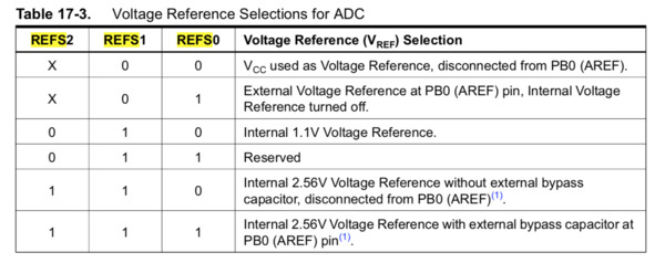
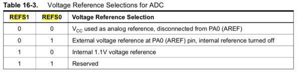
Voltage reference selections for ADC
| ATTiny45 | ATTiny44 |
|---|---|
 |
 |
Change lines (124 to 126) of the hello.txrx.45.c code made by Neil:
- initial for the ATTiny45
ADMUX = (0 << REFS2) | (0 << REFS1) | (0 << REFS0) // Vcc ref
   | (0 << ADLAR) // right adjust
   | (0 << MUX3) | (0 << MUX2) | (1 << MUX1) | (1 << MUX0); // PB3
- modified for the ATTiny44
ADMUX =  (0 << REFS1) | (0 << REFS0) // Vcc ref
   | (0 << ADLAR) // right adjust
   | (0 << MUX5)| (0 << MUX4)| (0 << MUX3) | (0 << MUX2) | (1 << MUX1) | (1 << MUX0); // PA3
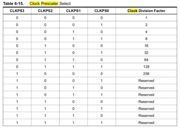
Clock prescaler select
To keep the good clock division factor (1) I needed to compare the table of the clock prescaler select for the ATTiny45 (table 6-15 page 32 of the datasheet) et ATtiny44 (table 6-11 page 32 of the datasheet):
| ATTiny45 | ATTiny44 |
|---|---|
 |
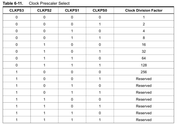 |
The line 113 remain unchanged for ATTiny44:
CLKPR = (0 << CLKPS3) | (0 << CLKPS2) | (0 << CLKPS1) | (0 << CLKPS0);
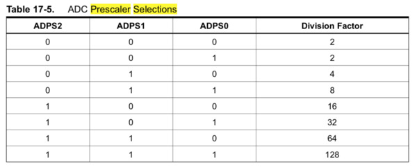
ADC prescaler selections
To keep the good division factor (128) I needed to compare the table of the ADC prescaler selections for the ATTiny45 (table 17-5 page 135 of the datasheet) et ATtiny44 (table 16-6 page 147 of the datasheet):
| ATTiny45 | ATTiny44 |
|---|---|
 |
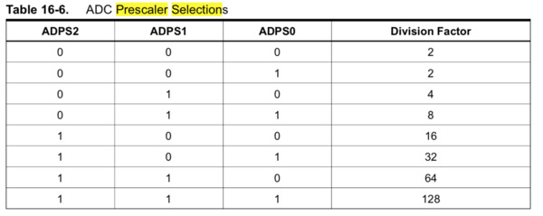 |
The lines 127 and 128 remain unchanged for ATTiny44:
ADCSRA = (1 << ADEN) // enable
   | (1 << ADPS2) | (1 << ADPS1) | (1 << ADPS0); // prescaler /128
Programming with Arduino IDE
After making the previous changes I use the arduino IDE and the FabTinyISP to upload the code. I opened the serial port and found that data was being transmitted.
Then i used the python script made by Neil to verify that the data received on the serial port corresponded to something. For that I used python 2.7. The up and down values are sent in two frames by the c++ program and they are combine in the python program. The sum of the up and down value is made in the python program.
To run the python script (here called “cap.py”) point his folder location and use CL (you have to select the right serial port “/dev/tty.usbserial-AH02F2I8”):
ben$ python cap.py /dev/tty.usbserial-AH02F2I8
Capacitive PCB with ATTiny44
The experimented method working on an ATTiny44, I decided to create a PCB. This one could serve me for my final project, to measure the humidity of the compost.
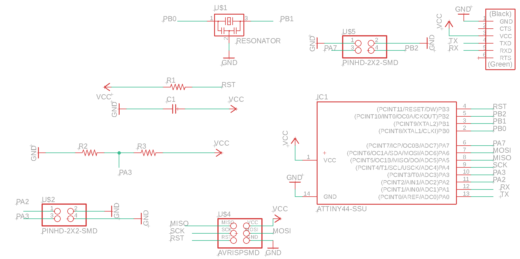
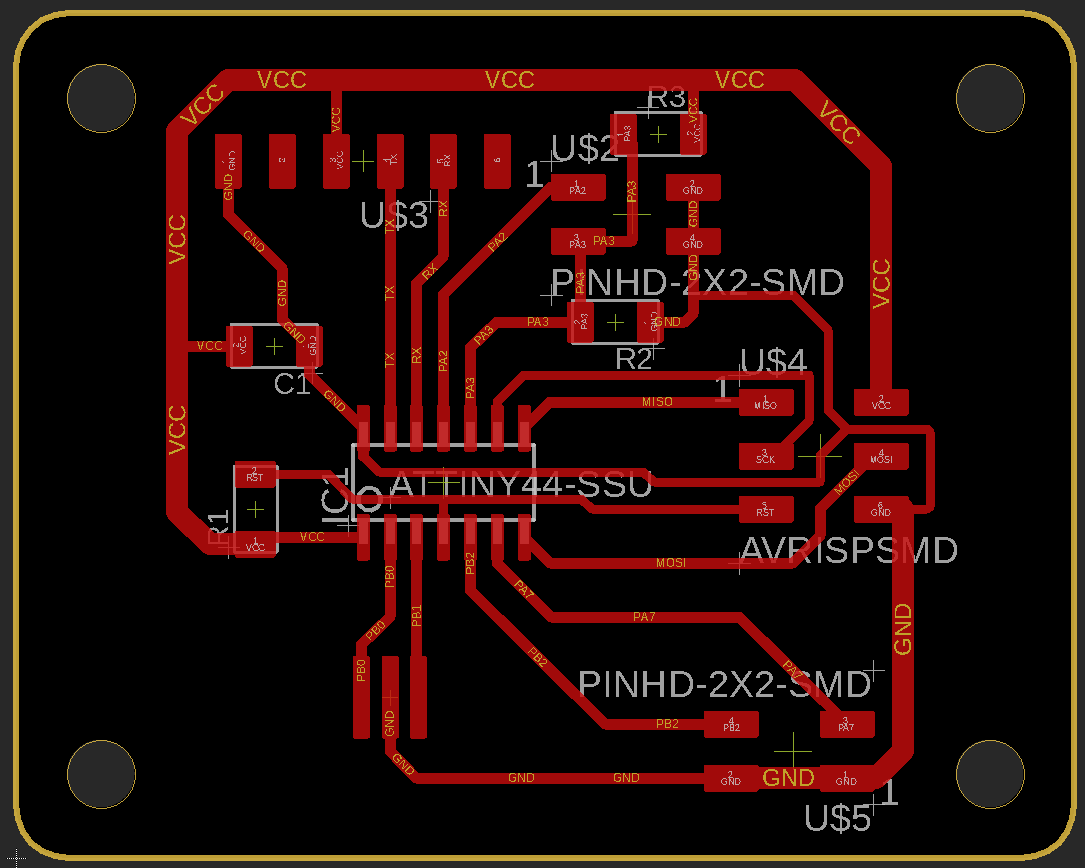
Design on Eagle
I based on the Eagle schematic made for my hello echo board to make this new PCB. I deleted the LED and button and added the voltage divider (with 1Mohms resistors ), and 2 pin headers (2x2), one for electrodes and one available for other possible needs.
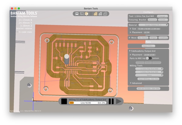
| Eagle schematic | Eagle board | Bantam visualization |
|---|---|---|
 |
 |
 |
Soldering
| The board milled | The board soldered |
|---|---|
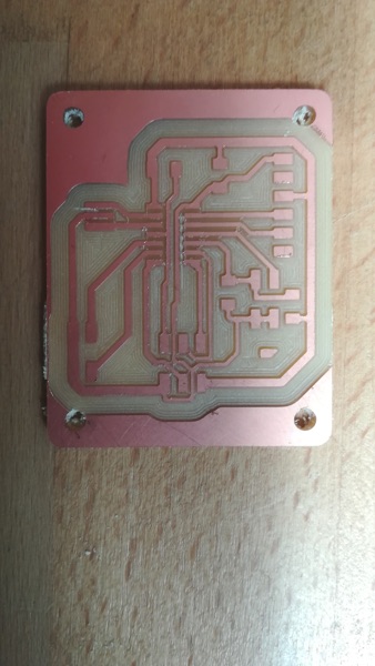 |
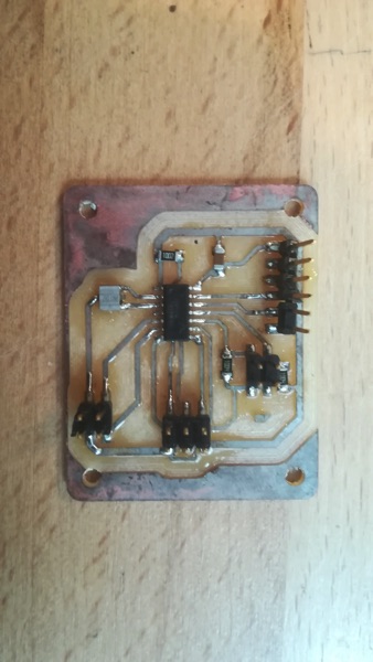 |
I uploaded the hello.txrx.45.c code modified for ATTiny44 code with Arduino IDE and run the python script and it works !
Downloads
hello.txrx.45.c code modified for ATTiny44
Input_capacitive Eagle schematic
Links
Pull request about variables types
Interesting informations about serial communication with ATtiny
Explanations about registers and channels (french)