
Context
Concerned by the global warming and as urban people I tried to find a manner to reduce my environmental impact. Like many French I am dependent on fossil and atomic energy. I wish I could do without it in the near future, but I am not able for the moment. In the meantime, I cycle, consume local products (where possible) and try to reduce my waste.
If it is easy to compost waste when you live in the countryside or just when you have a garden that allows it, it is more complicated when you live in town and have no garden.
Constraints
The worm composter is a beginning of solution because it allows to reduce significantly the volume of waste and it can be installed indoors. But there are several obstacles to its development:
- Psychological: the human knows how to generate waste but they must quickly disappear from his sight … with a worm composter the waste is degraded slowly and remain a moment in the home … and in addition there are worms that crawl under the rubbish
- Use: Start a worm composter is not necessarily easy. This requires observing the evolution of the waste and properly balancing the inputs. If this is not done correctly, smells, midges or other nuisances may appear.
- Drainage: when there is no garden where to value the compost, how to do?
Principle of worm composting
The worm composting (or vermicomposting) is a organic waste treatment technique. The process uses earthworms that feed on organic waste. Different varieties of worms can be used as Eisnia fetida, Eisenia hortensis, Eisenia andrei, or Perionyx excavatus. These worms eat the equivalent of their weight per day and reduce by 5 the initial volume that they have eaten. After digestion, the earthworms will reject a material devoid of odor, humus-like material called vermicompost.
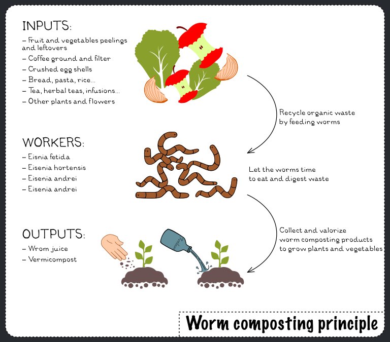
Benefits of vermicompost
The vermicompost is particularly rich in organic matter so it’s a very good organic fertilizer. As explain Iyyanki V. Muralikrishna and Valli Manickam in Environmental Management the vermicompost has the following advantages over chemical fertilizers:
- it restores microbial population, which includes nitrogen fixers, phosphate solubilizers, etc.,
- provides major and micro-nutrients to the plants,
- improves soil texture and water holding capacity of the soil,
- provides good aeration to soil, thereby improving root growth and proliferation of beneficial soil microorganisms,
- decreases the use of pesticides for controlling plant pathogens,
- improves structural stability of the soil, thereby preventing soil erosion,
- enhances the quality of grains/fruits due to increased sugar content.
To learn more about you can read “Friend earthworm : practical application of a lifetime study of habits of the most important animal in the world” written by George Sheffield Oliver who experienced vermicomposting.
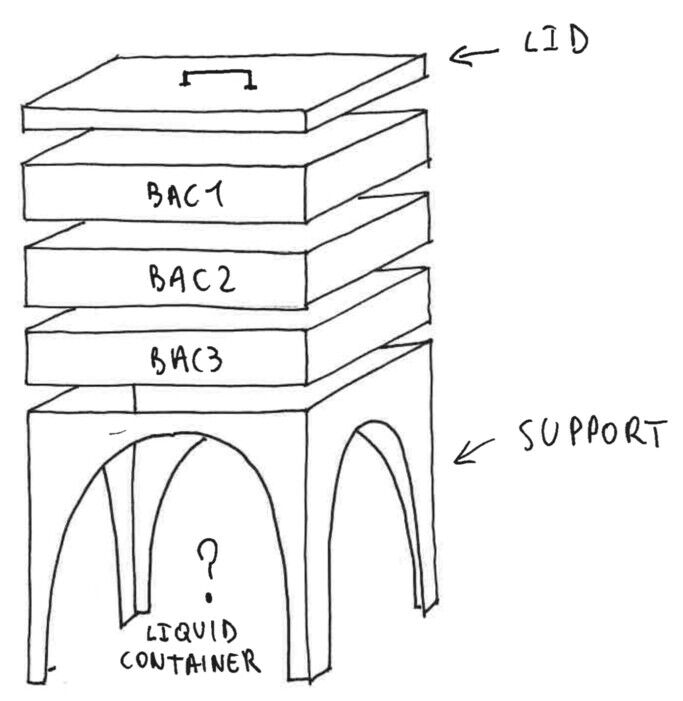
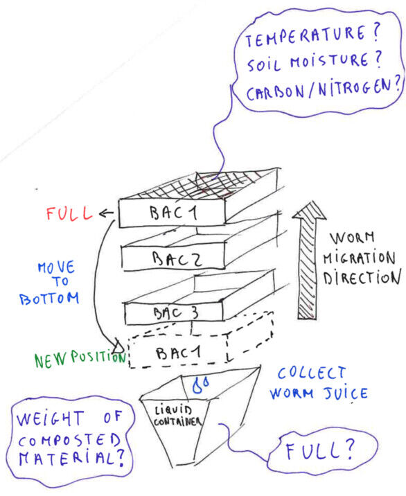
Operation of a worm composter
A worm composter is generally composed of a stack of trays in which the waste is placed in contact with the worms. The bottom of each trays is perforated to let the worms migrate from one tray to another. The waste is placed in the upper tray and the other trays contain the compost being matured. When the top tray is full, empty the tray with the oldest compost (normally ready if the composter is well sized) and place it at the top of the stack. In the lower part, a tank collects the worm juice produced during the composting process.
First sketch
| GENERAL DESIGN | OPERATION |
|---|---|
 |
 |
Aims of the project
I started thinking about this project 2 years ago, but have not had the opportunity to spend time and energy on it. I want to seize the opportunity of the Fabacademy to progress in the realization of a first version of the worm composter.
I separated the objectives into 2 categories those I set for my Fabacademy final project and those in the long and mid-term objectives.
Objectives for my Fabacademy final project
- Demonstrate my Fabacademy learning outcomes
- Get a working prototype allowing:
- to facilitate use by alerts (to ensure the right conditions in the composting process)
- to monitor data (temperature and humidity) during composting
- Find an attractive design
- Develop documentation to allow appropriation and upgrades by other users
Long and mid-term objectives
- Participate in a community of users sharing:
- advices
- worms to set up worm composter
- composter outputs (worm juice and compost)
- data
- digital fabrication files
- Improve the product by users feedback
- Monitor data during composting and correlate it with the user observation
Community
The plus2vers website is a French web platform that references worm donors and share informations and advices about worm composting.
State of art
DIY solutions
There are many DIY solutions of different shapes and using different materials. I did not find a DIY project using digital fabrication.
Here are some DIY examples:
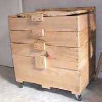
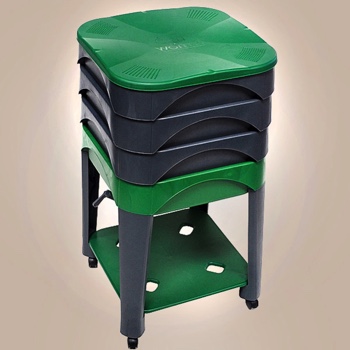
| Polystyrene tank | Plastic tray | Wood tray | |
|---|---|---|---|
| Pictures | 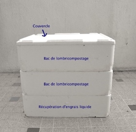 |
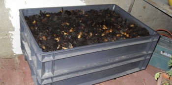 |
 |
| Link | Nature obsession | Nature obsession | Saint-Brieuc agglomération |
| Strengths | Good thermal insulation Lowcost |
Easy to build and maintain Light in weight |
Porous material for a good ventilation Good thermal insulation |
| Weaknesses | Esthetic Durability |
Bad thermal insulation Holds water |
Rapid deterioration heavy Dries faster |
| Cost | $ | $ $ | $ $ $ |
Commercial solutions
Commercial solutions exist at prices ranging from 65€ to 230€.
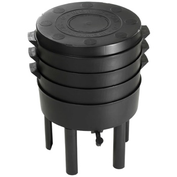
| Lombric&Co | Can-o-worms | Wood tray | |
|---|---|---|---|
| Pictures | 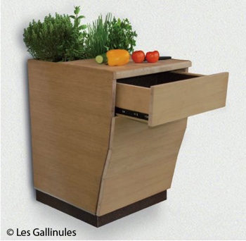 |
 |
 |
| Link | Les gallinules | Store | Vers la terre |
| Strengths | Esthetic Multifunctional |
Good documentation |
Wheels Ventilation |
| Weaknesses | On going development | Bad thermal insulation | Bad thermal insulation |
| Cost | ? | $ $ $ $ | $ $ $ $ |
Functional prototype description
Starting a worm composter is not easy when you do not know. This requires being vigilant with inputs, especially at startup. If it is badly managed, nuisances can appear (odors, midges …). Worm composter is also vulnerable to environmental pressures, especially to temperature and humidity. To facilitate the composting process it’s necessary to provide optimum conditions.
Worm composting requirements
- Temperature must not exceed 25°C nor fall below 15°C. Beyond these values the worms do not work (and below 0°C they die!). The optimum temperature is between 20°C and 25°C.
- Ventilation is an important parameter, indeed, worms are living beings and need oxygen
- Light is not required because worms live in the darkness
- Worms flee noise and vibrations
- Humidity: the environment must be wet, but not too much
- The ratio of carbon to nitrogen must be balanced
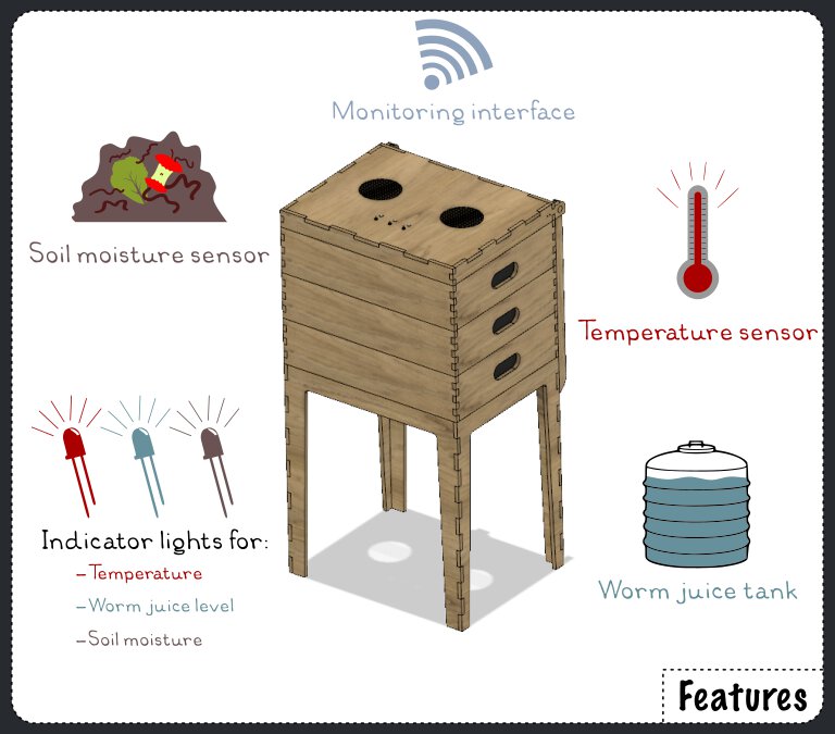
Features
For this prototype, I choose to respond primarily to the objectives mentioned above, so this one will integrate:
- Soil moisture, temperature and gauge level sensors to collect data
- Indicator lights to warn the user of good or bad composting conditions
- Stack of three trays
- Worm juice tank
- Customizable design to adapt the size of the worm composter to the user’s needs
- Web monitoring interface to follow the composting process
Parts
Here you will find the technical choices that I made to meet the objectives and achieve this prototype.
Materials
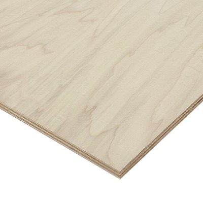
The choice of material for the tray is a complicated question because it must meet several requirements: - be resistant to a damp environment - innocuous for worms - machinable with the Fab Lab’s tools - esthetic (subjective !) - easily available
 |
 |
|---|---|
I made the choice to use machinable materials with laser cutting. This choice restricts the range of usable materials, but the laser cutting technique is more accessible for public who are not Fab Lab friendly than the CNC. In our Fab Lab we cut mainly poplar and okoume plywood and PMMA. Poplar is more easily cut with laser cutting and being a local species, so I chose this material.
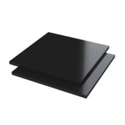
Poplar is not a wood species naturally protect from moisture. That’s why I thought about 2 ways to protect it, either a chemical protection or an inner protection plate in a resistant material.
At the beginning of the design phase I chose to cover the inner faces with PMMA plates. These plates were to serve as protection of the wood but also as a positioning guide and wrists. PMMA being a rather expensive material, I finally only kept the side plates (for the wrists and guide) and abandoned the full mechanical protection. I chose to protect the wood with a mixture of linseed oil and turpentine. I will have to observe how poplar evolve with this protection.
NEXT VERSION
For a next version I would like to test a solid wood to machine it with a CNC. I do not know yet which wood to choose, but preferably a local species (oak, chestnut, ash …?).
Mechanical parts BOM and budget
The design has been thought so that the composter can be made in a Fab Lab. The set consists of several parts.
BOM for a 955 x 500 x 390 mm vermicomposter
| Components | Quantity | Average price |
|---|---|---|
| Poplar plywood 10mm | 2 boards (600 x 900 mm) | 15€ |
| Poplar plywood 5mm | 1 board (150 x 70 mm) | 0,2€ |
| PMMA (black) 3mm | 1 board (770 x 500 mm) | 41€ |
| PMMA (transparent) 3mm | 1 board (130 x 70 mm) | 5€ |
| PLA filament 2,85 | 30 gram | 0,6€ |
| Exterior wood glue | 1 pot | 8€ |
| Turpentine oil | 1 pot | 6€ |
| Linseed oil | 1 pot | 4€ |
| Bottle | 1 | Free |
| Flexible pipe | 1 | 1,5€ |
| Screws (to fasten PCBs) | 16 | 0,5€ |
| Grid | 1 | 10€ |
Total budget for mechanical parts = 81,5€
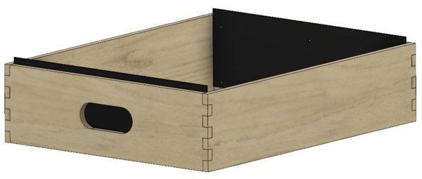
Trays
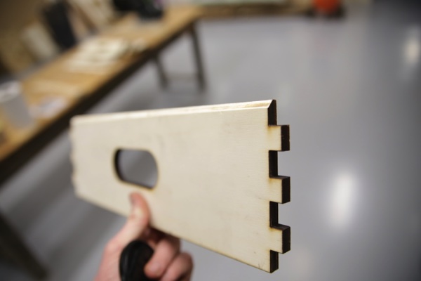
A stack of 3 boxes open on the top and bottom. Each is composed of 4 parts assembled by notches. A grid is placed at the bottom to hold the waste and allow the migration of worms. On the sides of each tray there are wrists to facilitate handling. To facilitate stacking the lower edges of the bins are bevelled and PMMA positioning guides are present on the sides.
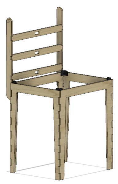
Stand
For better ergonomics, a stand raises the stack of trays. In this configuration the worm juice tank can be positioning in the lower part. The feet also serve as a support for the lid.The stand holds the soil moisture sensor in the first tray.
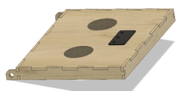
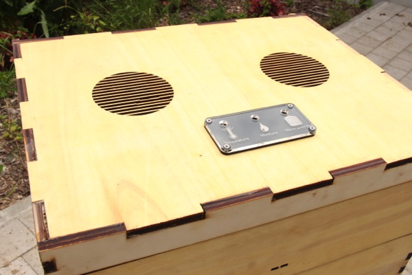
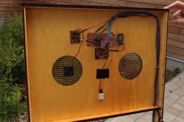
Lid
The lid is mounted on the stand by means of a laser-cut hinge system. The inside face of the lid houses the electronic cards, temperature sensor and the fan. Openings on the upper face facilitate the flow of air.
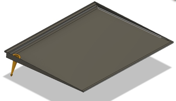
Worm juice collector
In the lower part, below the 3 trays, a sloped waterproof tray can collect the worm juice. A hole is present in the lowest point to drive the juice into the tank.
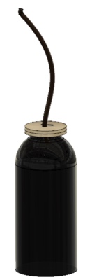
Worm juice tank
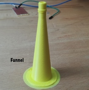
For this part I use a simple glass bottle. The worm juice is recovered and stored in a tank located at the feet of the vermicomposter. A funnel is placed at the collector hole, and a pipe brings the juice into the tank. A cap closes the tank and holds the humidity sensor used as a level gauge.
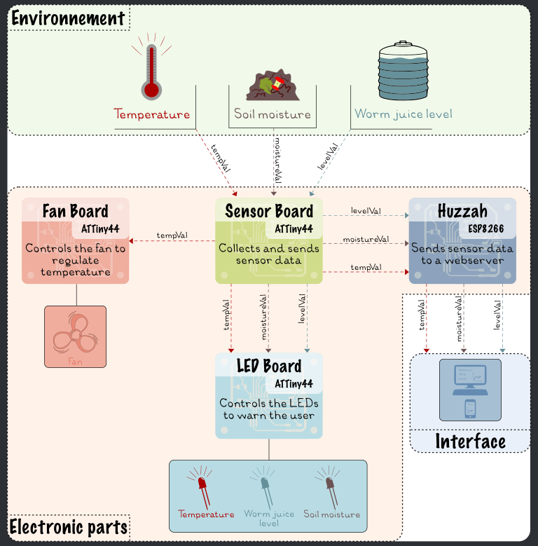
Electronic parts BOM and budget
For the prototype I chose to use the PCBs designed and produced during the fabacademy. The electronics must be able to retrieve several information related to the composting environment:
- the moisture of the compost
- the air temperature
- the level of worm juice in the tank
It must also allow:
- to alert the user to the composting conditions (local and network)
- to activate the fan if necessary (too wet or too hot) (to be confirmed during use !)
Here is the architecture:
| Components | Quantity | Average price |
|---|---|---|
| Electrical Wires (3 colors) | 1 coils | 6€ |
| Huzzah ESP8266 | 1 | 9€ |
| 12V Power supply | 1 | 17€ |
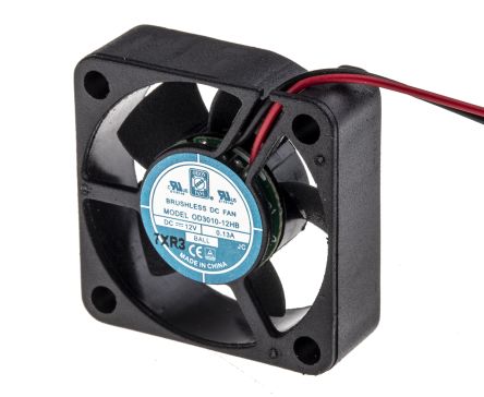
| Fan | 1 | 12€ |
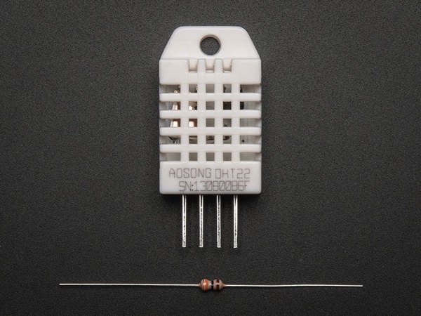
| DHT 22 | 1 | 9€ |
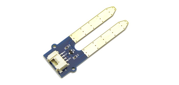
| Soil moisture sensor | 1 | 3€ |
| Polarized capacitor 470uF 25V | 1 | 0,5€ |
| Solder wire | 1 | 3€ |
Total budget for electronic parts = 59,5€
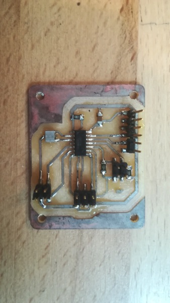
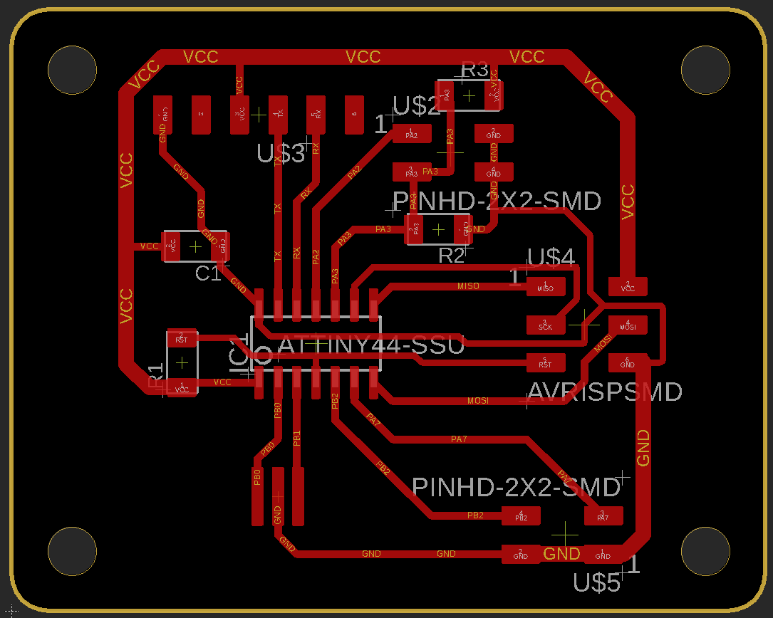
Sensor board
This PCB is responsible for recovering data from the 3 sensors:
- the temperature via the DHT22 sensor
- the moisture value in the compost via the DIY soil moisture sensor
- the level of worm juice in the tank
This data is sent in serial port to the other PCBs.
| Components | Quantity | Average price |
|---|---|---|
| FR4 Epoxy PCB Board single side | 1 boards (100 x 150 mm) | 1,5€ |
| ATTiny44 | 1 | 1,4€ |
| Crystal 20Mhz 8pF SMD | 1 | 0,5€ |
| Resistor 10kohms SMD | 1 | 0,1€ |
| Resistor 1Mohms SMD | 2 | 0,2€ |
| Capacitor 1uF SMD | 1 | 0,1€ |
| Pin Header (ISP - 6pos) | 1 | 0,2€ |
| Pin Header (FTDI - 6pos) | 1 | 0,15€ |
| Pin Header (4pos*) | 2 | 0,30€ |
Total budget for sensor board = 4,45€
 |
 |
|---|---|
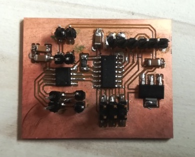
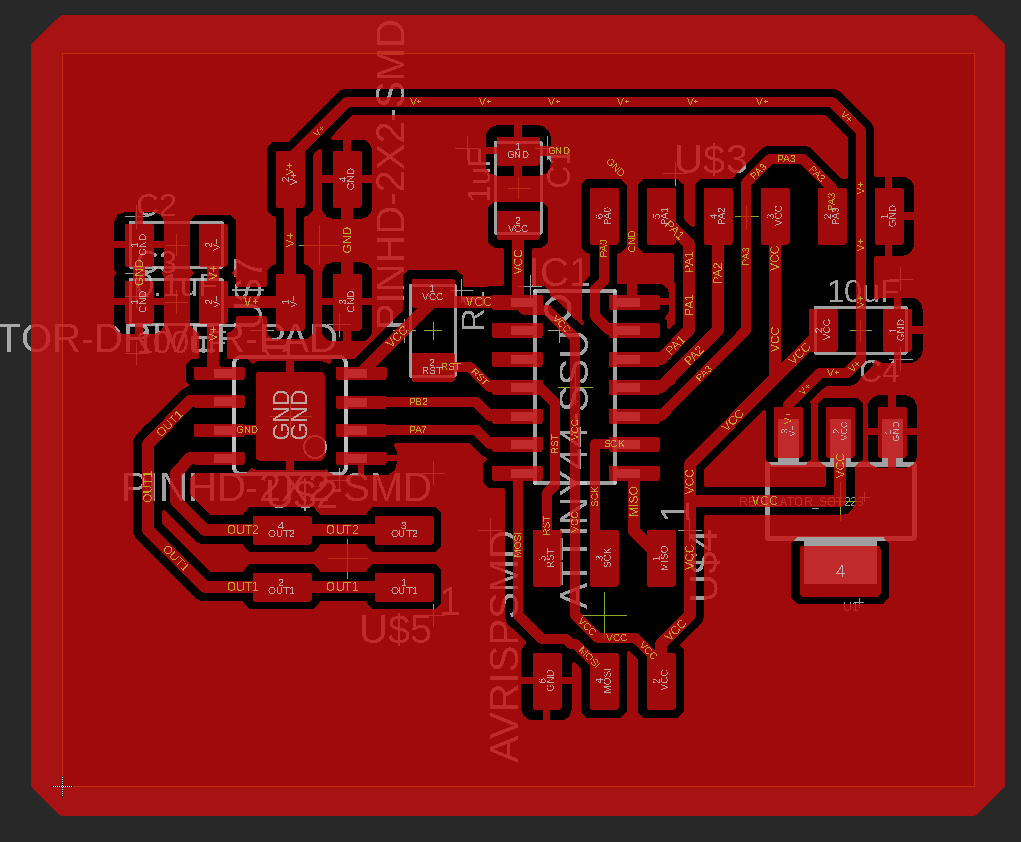
Fan board
This PCB receives the temperature and humidity of the compost and controls the fan (starts if too hot or too wet). This board is powered by the 12v power supply and is equipped with a regulator that supplies the voltage of 5V to other components.
| Components | Quantity | Average price |
|---|---|---|
| FR4 Epoxy PCB Board single side | 1 boards (100 x 150 mm) | 1,5€ |
| ATTiny44 | 1 | 1,4€ |
| Resistor 10kohms SMD | 1 | 0,1€ |
| Capacitor 10uF SMD | 1 | 0,1€ |
| Capacitor 1uF SMD | 1 | 0,1€ |
| Capacitor 0,1uF SMD | 1 | 0,1€ |
| Capacitor 100uF SMD | 1 | 0,1€ |
| 5V regulator NCP1117ST50T3GOSCT-ND | 1 | 0,5€ |
| Motor driver A4953ELJTR-T | 1 | 1,6€ |
| Pin Header (ISP - 6pos) | 1 | 0,2€ |
| Pin Header (FTDI - 6pos) | 1 | 0,15€ |
| Pin Header (4pos*) | 2 | 0,30€ |
Total budget for fan board = 6,05€
 |
 |
|---|---|
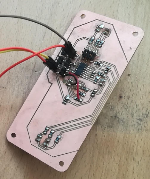
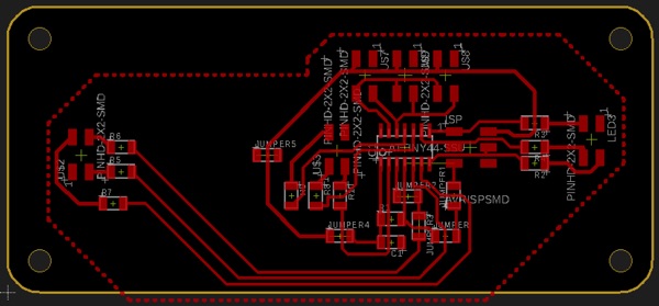
LED board
This PCB receives temperature, humidity of the compost and value of the soil moisture sensor used as gauge level and controls 3 LEDs (one for each data).
| Components | Quantity | Average price |
|---|---|---|
| FR4 Epoxy PCB Board single side | 1 boards (100 x 150 mm) | 1,5€ |
| ATTiny44 | 1 | 1,4€ |
| Resistor 10kohms SMD | 1 | 0,1€ |
| Resistor 1kohms SMD | 9 | 0,9€ |
| Resistor 0 ohms SMD (jumpers) | 5 | 0,5€ |
| Capacitor 1uF SMD | 1 | 0,1€ |
| Pin Header (ISP - 6pos) | 1 | 0,2€ |
| Pin Header (4pos) | 6 | 0,90€ |
| RGB LEDs | 3 | 0,50€ |
Total budget for LED board = 6,10€
 |
 |
|---|---|
Huzzah ESP8266
Huzzah receives temperature, humidity of the compost and value of the soil moisture sensor used as gauge level and send data to a webserver.
DHT 22
This sensor is only used to monitor air temperature.
Temperature range: -40°C to 80°C
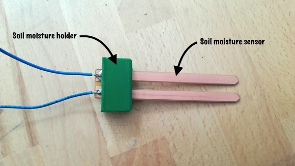
Soil moisture sensor
This sensor is used as a gauge of the worm juice tank.
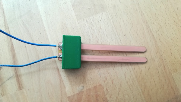
DIY compost moisture sensor
Following Neil’s advice, I created a humidity sensor based on a capacitive circuit with 2 electrodes.
| Components | Quantity | Average price |
|---|---|---|
| FR4 Epoxy PCB Board single side | 1 boards (100 x 150 mm) | 1,5€ |
| PLA | 4grams | 0,10€ |
Total budget for DIY compost moisture sensor = 1,6€
Fan
I use a 12v fan placed on the lid to force ventilation especially when the temperature or humidity are too high.
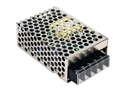
12V Power supply
I chose this power supply for its size and because it is sufficient to power all the electronic components.
Total budget
| Components | Average price |
|---|---|
| Mechanical parts | 91,5€ |
| Electronic parts | 59,9€ |
| Sensor board | 4,45€ |
| Fan board | 6,05€ |
| LED board | 6,10€ |
| DIY compost moisture sensor | 1,6€ |
| TOTAL | 159,6€ |
!!! note “COST REDUCTION” For the next version I would like to check if it is necessary to keep the fan. The use of a solid and moisture-resistant wood could help to remove the PMMA side panels. So the total cost could go down to 110€.
DIY moisture sensor calibration
On Neil’s advice I made a capacitive sensor to measure the moisture tux in the compost. To know more about the operation see here.
The objective of the measurement is to obtain a value between 0% (for dry medium) and 100% (for medium saturated with water).
To calibrate it, I made measurements in a dry soil and in a water saturated soil and I compared the values given by a commercial soil moisture sensor
| Dry soil | 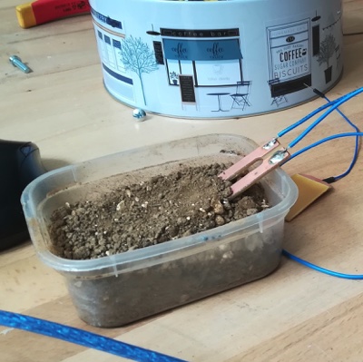 |
 |
|---|---|---|
| Water saturated soil | 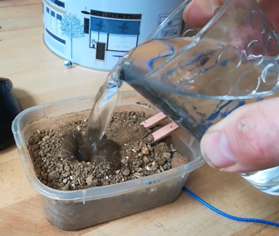 |
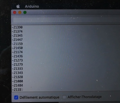 |
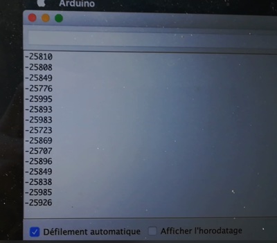
I got the following final values:
| Soil | Value DIY sensor | Value commercial sensor |
|---|---|---|
| Dry soil | -24 000 | 0% |
| Water saturated soil | -19 900 | 100% |
| Air | -27 800 | 0% |
!!! note “CALIBRATION” To obtain roughly stable values, it took 10 to 15 minutes !! To improve the response of the sensor and to adapt it to the use, it would be necessary to vary the delay between the pulsations.
Use of the DHT22 without library on the ATTiny44
The library for using the DHT22 temperature probe takes too much memory to be used on an ATTiny44. Needing only the temperature and not the humidity I integrated the reading of the probe directly in a function of the code for the INPUT board. So, I did not need the library anymore.
int temp ()
{
  int val = 0;
  if (read())
  {
    int f;
    f = (int)(data[2] & 0x7F);
    f *= 256;
    f += (int) data[3];
    f /= 10;
    if (data[2] & 0x80) f *= -1;
    val = f ;
  }
  return val ;
}

boolean read(void) {
  uint8_t laststate = HIGH;
  uint8_t counter = 0;
  uint8_t j = 0, i;
  unsigned long currenttime;

  // pull the pin high and wait 250 milliseconds
  digitalWrite(7, HIGH);
  delay(250);

  currenttime = millis();
  if (currenttime < _lastreadtime) {
    // ie there was a rollover
    _lastreadtime = 0;
  }
  if (!firstreading && ((currenttime - _lastreadtime) < 2000)) {
    return true; // return last correct measurement
    //delay(2000 - (currenttime - _lastreadtime));
  }
  firstreading = false;
  //
    //Serial.print("Currtime: "); Serial.print(currenttime);
    //Serial.print(" Lasttime: "); Serial.print(_lastreadtime);

  _lastreadtime = millis();

  data[0] = data[1] = data[2] = data[3] = data[4] = 0;

  // now pull it low for ~20 milliseconds
  pinMode(7, OUTPUT);
  digitalWrite(7, LOW);
  delay(20);
  cli();
  digitalWrite(7, HIGH);
  delayMicroseconds(40);
  pinMode(7, INPUT);

  // read in timings
  for ( i = 0; i < 85; i++) {
    counter = 0;
    while (digitalRead(7) == laststate) {
      counter++;
      delayMicroseconds(1);
      if (counter == 255) {
        break;
      }
    }
    laststate = digitalRead(7);

    if (counter == 255) break;

    // ignore first 3 transitions
    if ((i >= 4) && (i % 2 == 0)) {
      // shove each bit into the storage bytes
      data[j / 8] <<= 1;
      if (counter > 6)
        data[j / 8] |= 1;
      j++;
    }

  }

  sei();

  // check we read 40 bits and that the checksum matches
  if ((j >= 40) &&
      (data[4] == ((data[0] + data[1] + data[2] + data[3]) & 0xFF)) ) {
    return true;
  }


  return false;

}
Fabrication process
Mechanical Parts
1st. step: to set the dimensions
- Download the Fusion file
- Set the parameters (see here to know how to do)
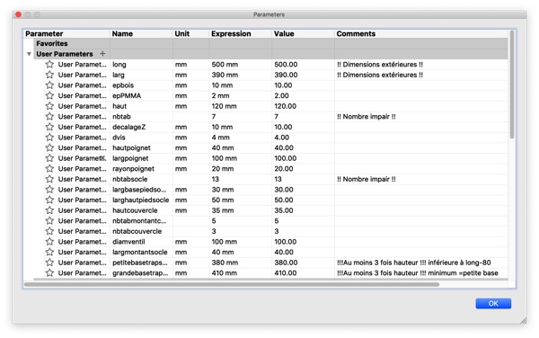
- Fix errors if necessary
- Create new drawing in fusion to export panels into PDF file
2nd. step: production
Download and laser cut or print this parts (or use your own files created previously from the parametric model):
| Parts | Material | Tool |
|---|---|---|
| Stand / Trays / Lid (1)(SVG, PDF, DXF) | Poplar 10mm Plywood | Laser cutting |
| Stand / Trays / Lid (2)(SVG, PDF, DXF) | Poplar 10mm Plywood | Laser cutting |
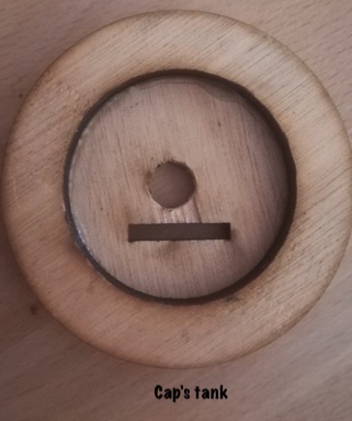
| Cap’s tank (SVG, PDF, DXF) | Poplar 5mm Plywood | Laser cutting |
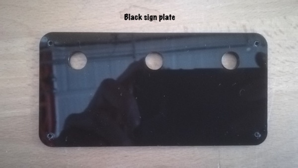
| Inner PMMA side plates, guides and LEDs sign plate (SVG, PDF, DXF) | 3mm black PMMA | Laser cutting |
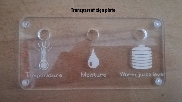
| LEDs sign plate (SVG, PDF, DXF) | 3mm transparent PMMA | Laser cutting |
| DIY_soil_moisture (SVG, PDF, DXF) | FR4 Epoxy PCB board | Milling machine |
| Funnel (STL) | PLA | 3D printer (FDM) |
| Soil moisture holder (STL) | PLA | 3D printer (FDM) |
| Worm juice collector | Molding products, fibers, solid wood | CNC |
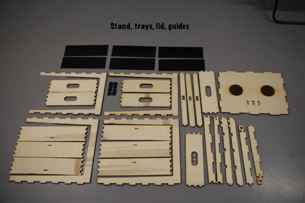
You should have all this parts:
 |
 |
|---|---|
 |
 |
 |
 |
3rd. step: post-processing
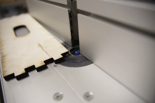
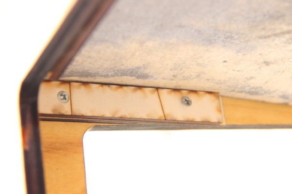
To facilitate stacking of the trays the lower edges of the bins must be bevelled. To do you can use a spindle moulder machine with a 90° Vbit.
 |
 |
|---|---|
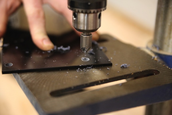
To allow penetration of the screw heads it is necessary to make conical holes in the PMMA guides and side panels.
 |
 |
|---|---|
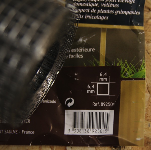
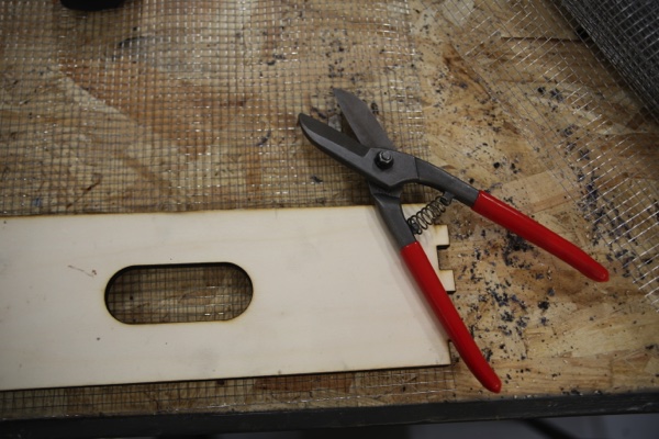
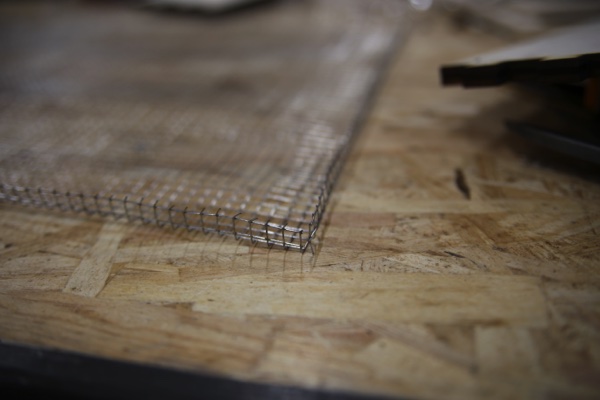
4th. step: the grid
A grid is placed at the bottom of the trays to hold the waste and allow the migration of worms. I used 6,4mm mesh grid.
| Cut the grid with (+10 mm offset) | Fold the grid on each side |
|---|---|
 |
 |
After assembling the trays, the grids will be stapled in the bottom on each side.
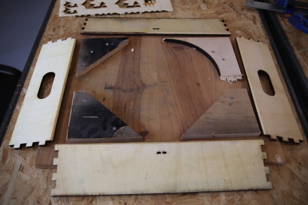
5th. step: assembly
To facilitate the assembly and especially to ensure the squareness of the trays, it is advisable to create a jig.
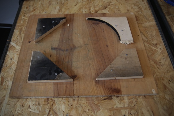
| Place the panels and test the assembly without glue | Glue the notches |
|---|---|
 |
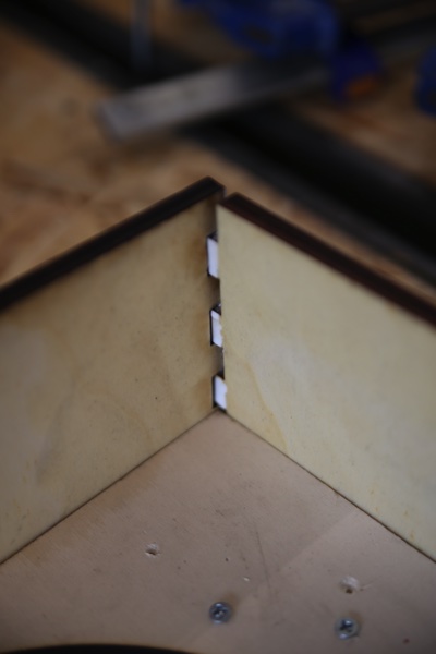 |
| Put the panels together | Use clamps to tighten |
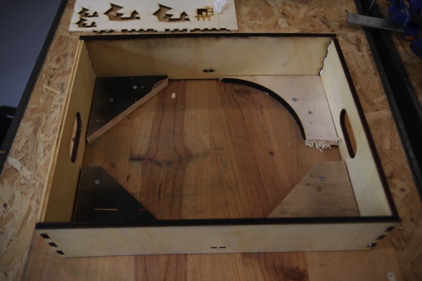 |
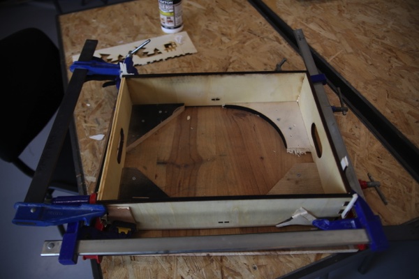 |
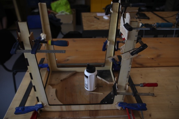
Use the same technique for the lid and the stand.
6th. step: chemical protection
Apply two coats of a 50/50 mixture of turpentine and linseed oil on every wood parts.
7th. step: fastening the grid
Staple the grids inside each tray.
8th. step: fastening the inner PMMA side plates
Fasten the inner PMMA side plates with screws. The edges of the grid is thus blocked under the PMMA plates.
9th. step: make the worm juice collector
10th. step: instal the worm juice collector
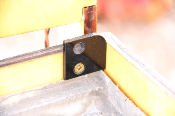
As I did not know what the collector would look like at the time of the design, the fastening system is not integrated in the 3D model. I simply used plywood brackets screwed onto the stand to hold the collector. It is important to respect the slope of the collector during installation.
11th. step: fastening the inner PMMA guides on the stand
Fasten the PMMA guides with screws.
12th. step: fastening the LED sign plates
13th. step: install the pipe and the tank’s cap on the Bottle
Electronic Parts
1st. step: make the PCB’s
2nd. step: upload code to each microcontroller - Sensor board code - Fan board - LED board code
3rd. step: fasten the PCBs to the Lid
Use small screws and make sure you do not short circuit !
4th. step: fasten the FAN to the Lid
Use cyanolit glue to fasten the FAN.
5th. step: wiring
Fan board:
- V+ -> V+ power supply
- GND -> V- power supply
- OUT2 -> V+ Fan
- OUT4 -> GND Fan
- GND (FTDI header)-> GND LED board
- VCC (FTDI header)-> VCC LED board
- PA2 (Tx FTDI header)-> PA2 (Tx) LED board
!!! note “POWER SUPPLY” You need to add a 470uF capacitor between V+ and V- of the power supply.
Sensor board:
- PA8 -> DIY moisture sensor electrodes (1)
- PA9 -> DIY moisture sensor electrodes (2)
- PA10 -> Signal DHT22
- VCC (ISP header) -> VCC DHT22
- GND -> GND DHT22
- PB6 -> signal gauge sensor
- GND (FTDI header) -> GND LED board
- VCC (FTDI header) -> VCC LED board
- PA1 (Rx FTDI header) -> PA2 (Tx) LED board
!!! note “DHT22” You need to add a 10kohm resistor between VCC and signal of the DHT22.
LED board:
- VCC (ISP header) -> VCC gauge sensor
- GND (ISP header) -> GND gauge sensor
- VCC -> VCC HUZZAH
- GND -> GND HUZZAH
- PA2 (Tx)-> Rx HUZZAH (as written on the FTDI Huzzah pin !!!) *
- GND -> GND Fan board (FTDI header)
- VCC -> VCC Fan board (FTDI header)
- PA2 (Tx) -> PA2 Fan board (Tx FTDI header)
- GND -> GND Sensor board (FTDI header)
- VCC -> VCC Sensor board (FTDI header)
- PA2 (Tx) -> PA1 Sensor board (Rx FTDI header)
HUZZAH: - VCC -> VCC LED board - GND -> GND LED board - Rx * -> PA2 (Tx) LED board
!!! note ” * Rx Tx” the name of rx and tx is reversed between the huzzah FTDI and the FTDI of the produced PCBs.
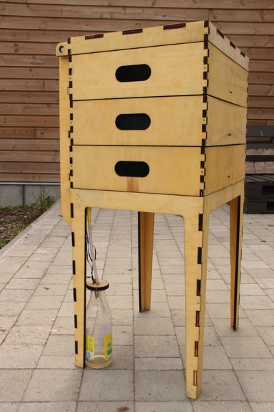
Final result
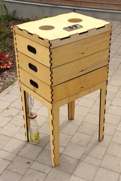
Conclusion
The work done allowed me to reach almost all the objectives that I had set for this first version of the vermicomposteur realized as part of the fabacademy.
- Demonstrate my Fabacademy learning outcomes
- Get a working prototype
- Find an attractive design
- Develop documentation to allow appropriation and upgrades by other users
However, as design and manufacturing progressed, I realized several areas for improvement.
-
About the choice of materials, I would like to get rid of PMMA. This would lower the cost of production, but requires a thorough study of the species of wood that might be suitable.
-
On the tools used, I would like to adapt the design to allow the production of parts at the CNC. This will allow me to work with a wider range of materials and in thicknesses greater than 10mm. The use of a CNC will also create the chamfers on the edges of the trays to reduce the time of post-processing (use of a spindle moulder machine …).
-
Regarding electronics, I would like to simplify the architecture. Keep a microcontroller for the sensors, and one for the LEDs and fan. The idea is to make a single PCB integrating all the components. This will avoid wired connections.
-
Regarding the humidity sensor, the capacitive measurement principle works, but needs to be improved to obtain more stable values.
-
Regarding the mechanical design, several things could be integrated as the tank support, the collector and power supply fixing.
Overall, I’m happy with the result and I hope this project will inspire other worm breeders!