9. Embedded programming
My goal this week was to figure out a easy workflow to flash the ATtiny44 and upload the code to the Echo Hello board I fabricated in Week 7.
After many hours of trying things and researching online how to get it to work I was finally able to flash the chip and upload my code using my FABisp and Arduino programming environment.
Button Control LED w/ Serial Feedback Code - Arduino
Here is the simplest code I could write to provide serial feedback and control and LED with a button.
#include <SoftwareSerial.h> //library that allows you to define digital pins as TX/RX pins for serial communication
#define RX    0   // Pin 0 //this is me establishing a variable to define which pins on the ATtiny44 I am going to use for Tx/RX pins
#define TX    1   // Pin 1

const int buttonPin = 7;     // variable defining the pushbutton pin
const int ledPin =  2;      // variable defining the LED pin


int buttonState = 0;         // variable for storing/reading the pushbutton status

SoftwareSerial Serial(RX, TX); //this is referenceing a function in the SoftwareSerial library. (RX,TX) is referencing the variables defined above. I could also just put 1 and 0 in instead of TX,RX but TX,RX is easier to follow through the code.

void setup() {

 Serial.begin(9600); //defining the communication speed
  Serial.println("Initializing..."); //printing something to serial to ensure the serial communication is working

  // initialize the LED pin as an output:
  pinMode(ledPin, OUTPUT);
  // initialize the pushbutton pin as an input:
  pinMode(buttonPin, INPUT);
}

void loop() {

  // read the state of the pushbutton value and storing it in the buttonState int variable. a 1 would be HIGH/on/button pushed and 0 would be LOW/off/button not pushed:
  buttonState = digitalRead(buttonPin);

  // check if the pushbutton is pressed. If it is, the buttonState is HIGH:
  if (buttonState == HIGH) {
    // turn LED on:
    digitalWrite(ledPin, HIGH);
   Serial.println("on..."); // print something to serial indicating the button is pushed and the LED is on
  } else {
    // turn LED off:
    digitalWrite(ledPin, LOW);
    Serial.println("off..."); // print something to serial indicating the button is not pushed and the LED is off
  }
}
Data Sheet
Since I’m using the Atmel 44 chip for the board I’m building this week I chose to read through that datasheet.
If I’m honest I had to treat the datasheet like classic book, just keep reading and hope it makes sense eventually. It tooks me about 2 hours to read though everything. Most of it went over my head but I didn’t find a couple of things interesting and useful. By far the most useful is that diagram at the top that outlines the purpose for all the chip’s legs. It allso provides the mearsurments for all aspects of the electronic component it documents. These measurment are perfect for designing custom parts in Eagle that aren’t easily found in a library of parts.

One part of my porject is an outdoor sensor that I plan to place in a plastic box. I have been a bit worried about the temperature in Houston under direct sunlight. The datasheet actually gives the min and max temp. the ATtiny chip will work. At 125 degree C being the MAX temp. even on a day of 110 degree F I will still be well in the operating limits.

Trouble with FabISP
I figured it would be easier to figure one thing out at a time. The Arduino IDE is a familiar program so I wanted to start by programing the ATtiny44 board via the FABisp using the Arduino program. Once that was working I figured I would know the board worked and could figure out programming it was C via command line.
I started by installing the windows arduino board library for the ATtiny chips.
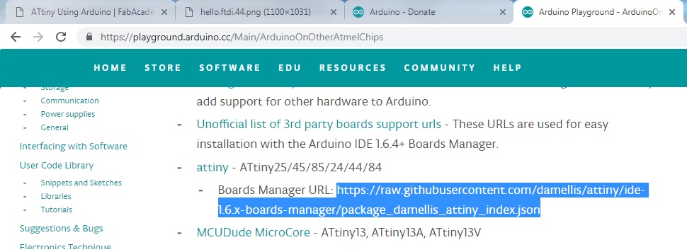
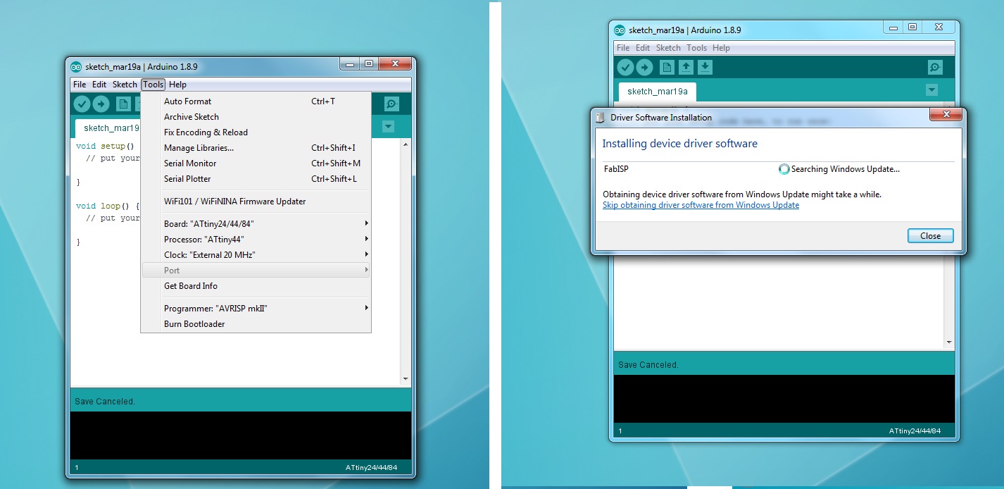
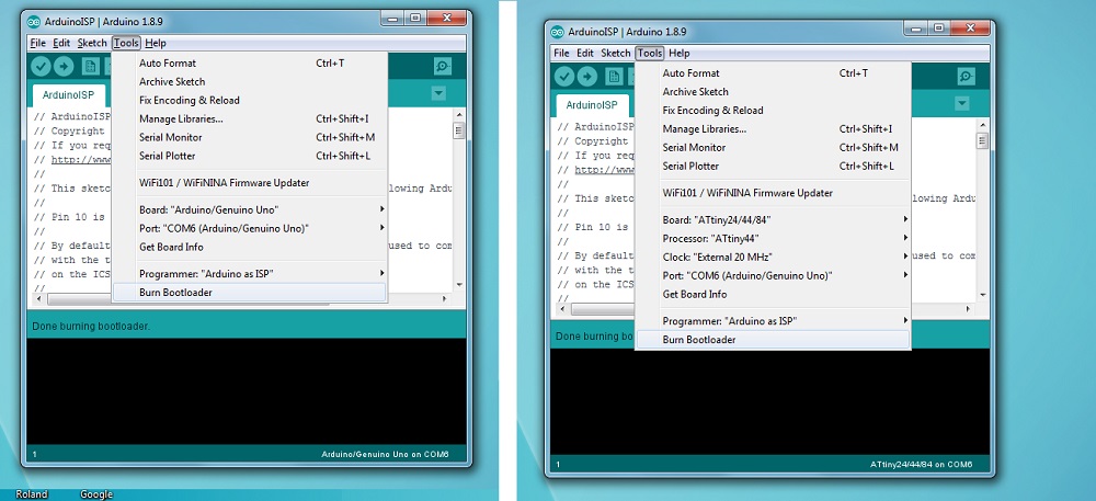
Once I loaded the Board Manager library for the ATtiny chips I could select the correct settings under TOOLS for the board.
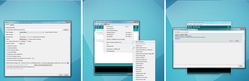
- Board: ATtiny24/44/84
- Processor: ATtiny44
- Clock: External 20 MHz
I have used Arduino for many year and I was stuck when the Port wouldn’t let me select it. Historically, this has always meant the USB cable was bad or the USB drivers for microprocessor needed be installed. I checked the cable and drivers, but both seemed to be correct.
Spiral Development - Top Down
I decided to switch to top down spiral development. Instead of trying to get the FABisp to work for the first time I decided to use the Arduino as my ISP since I have done that and know it works.
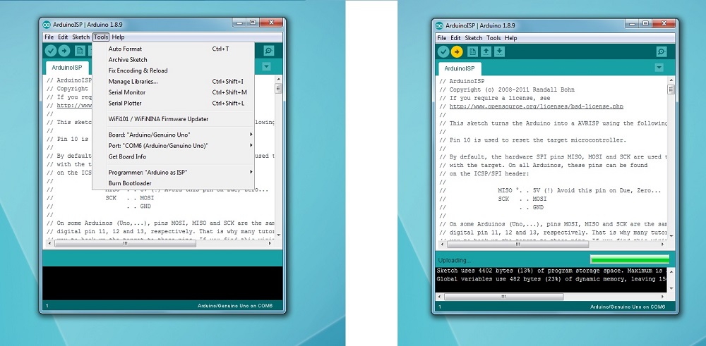
I switched the settings back to the default Arduino Uno and was able to select the COM port when the Arduino was plugged in. Then, I uploaded the ArduinoISP code.
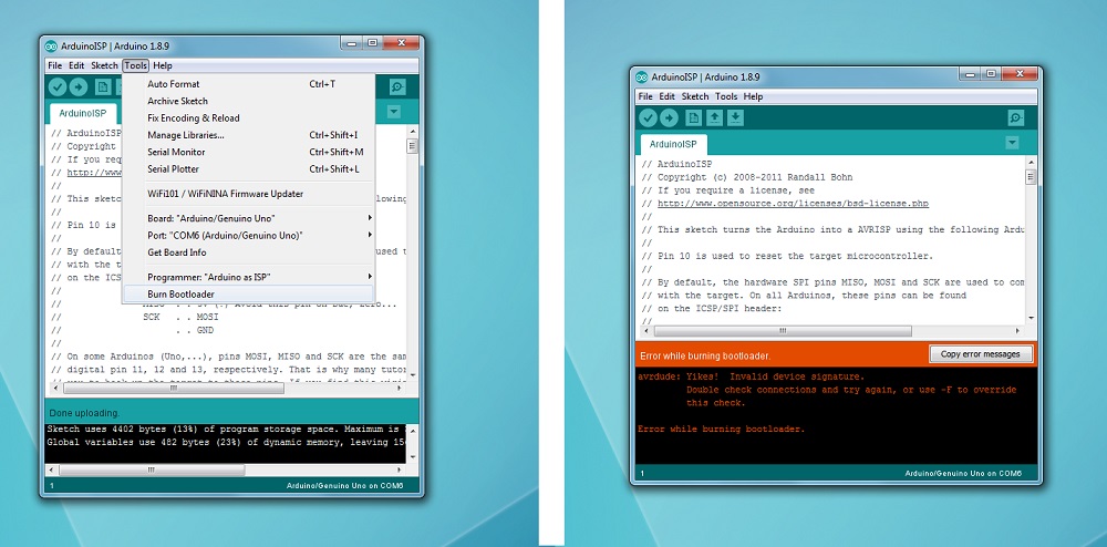
It seemed that no matter what I did for the next hour or so I got the same error when trying to burn the bootloader.
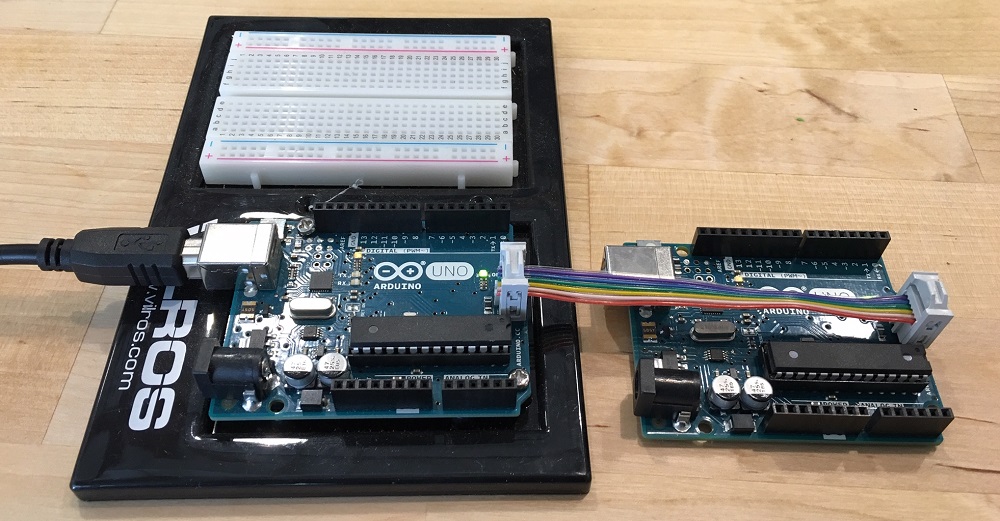
So I moved one step further back with the Topdown aproach and made sure I could load the bootloader to one Arduino from another arduino.
When I tried this and I got the same error I knew I was doing something wrong and it was a hardware problem.
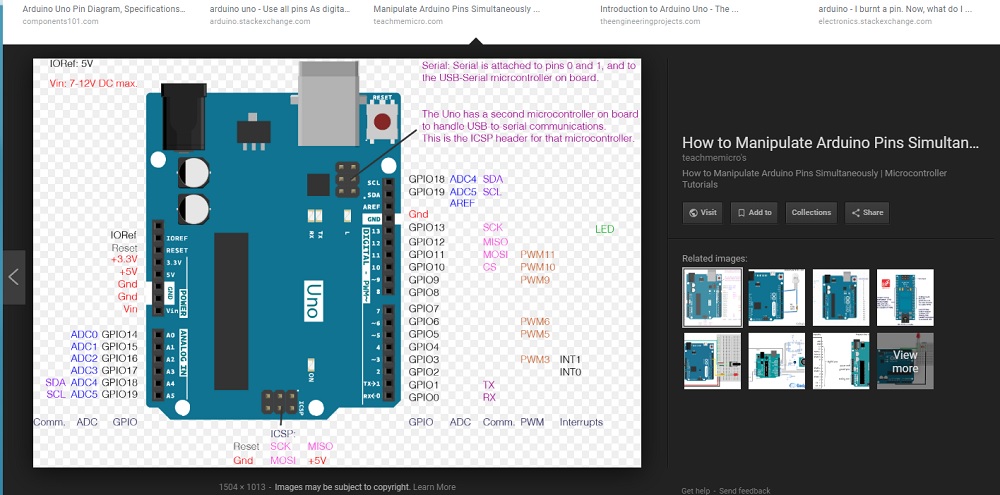
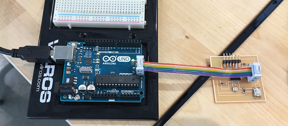
I googled the pin layout for Arduino and also read that the ISP CS pin needed to connect to RST on the chip being flashed with the bootloader.
I used jumper wires to go directly from the arduino pins instead of trying to go from ICSP port to ICSP port.
SUCCESS!!! With the correct board settings selected for each board being flashed I was able to use the Arduino to program another Arduino and my fabricated fabISP.
Programming with FabISP
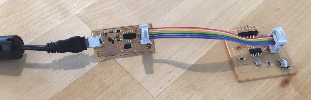
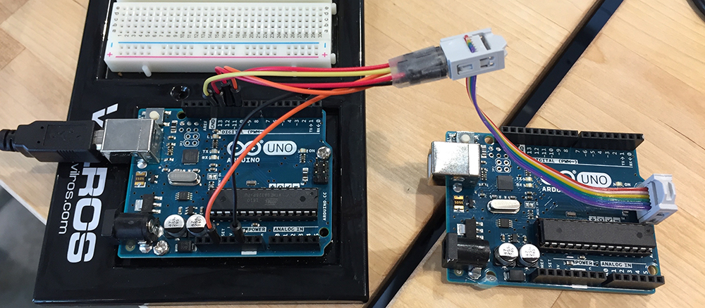
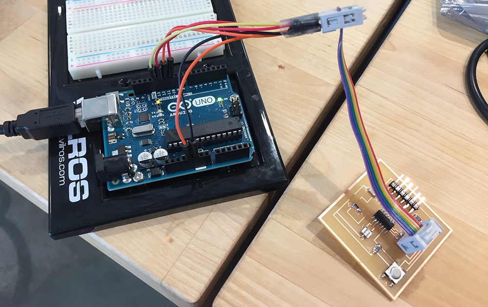
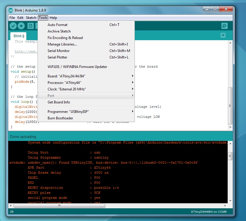
Finally, I decided, on a whim, to hook up the fabISP and see if the COM port would appear in the menu. When it still didn’t appear I decided to try it anyways. Turns out when using the fabISP you don’t have to select a COM port and you can use the ArduinoISP program with the FABisp to flash another ATtiny chip.
Below you can see the setting to program the ATtiny44 board with the FabISP. Notice the program has to be changed to USBtinyISP. - Board: ATtiny24/44/84 - Processor: ATtiny44 - Clock: External 20 MHz - Programmer: USBtinyISP
Atmel Studio
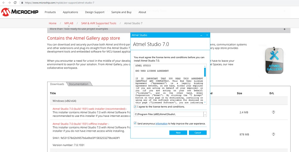
In an attempt to learn something new and program with more than one language I downloaded Atmel Studio. No one at Fab Lab Houston knows C so I am on my own trying to figure it out. I am going to try some top down troubleshooting. I found a youtube video of a guy showing how to write a blink code in C and uploading it to the Arduino via Atmel Studio. I understand the Arduino so I am going to try to get that to work, following his instructions, then move on to the FAB made ATtiny44 Hello board.
#define F_CPU 16000000

#include <avr/io.h>
#include <util/delay.h>
//Beginning of Auto generated function prototypes by Atmel Studio
int main(void );
//End of Auto generated function prototypes by Atmel Studio


int main (void)
{
    // set all PORTB pins for output
    DDRB = 0xFF;

    for (;;) {
        // toggle PORTB pins
        PORTB ^= 0xFF;
        // wait one second
        _delay_ms(1000);
    }
    return 0;
}
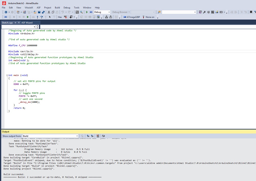
I was able to test the code in Atmel Studio. Then, I pushed it to the board with Arduino Builder. This program can push C over serial and it worked perfect.
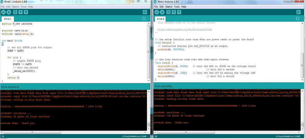
I wasn’t able to figure out how to get Atmel Studio to upload to the Arduino or my Tiny44 board. Then, I realized I could just use the Arduino program to upload C. I pasted the C written and verified in Atmel Studio into the Arduino program it is uploaded perfect.
I was also able to print out the Flash memory a basic blink code would take in C and Arduino. Look at the difference below.