10. Molding and casting
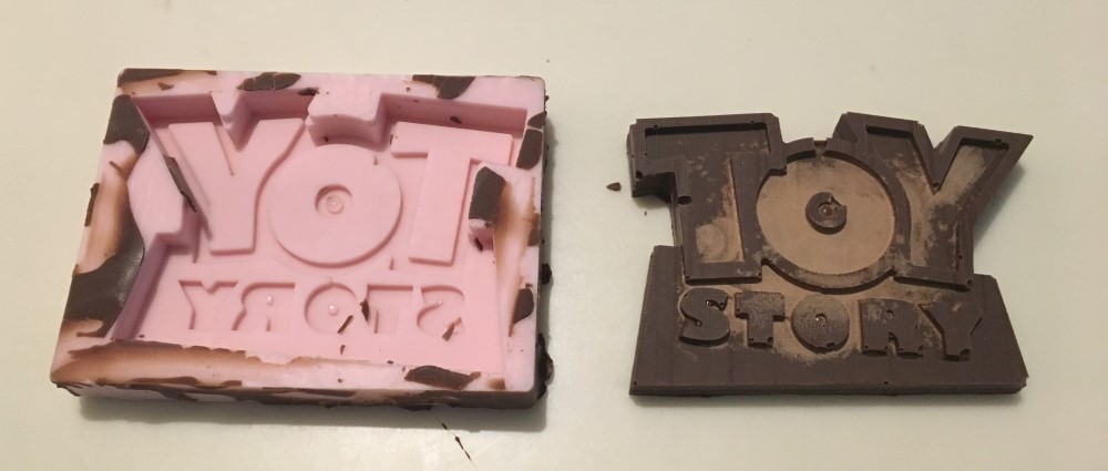
The modeling and casting on my final project will be a rubber mold from a 3D print. Since this week is focused on using a CNC mill to create a blank to pour a rubber mold over, I decided to do a fun project with my son. He is obsessed with Toy Story and can’t wait to see the new movie. He has also been watching a ton of youtube videos about candy factories. This week I decided to make a mold of the toy story logo since it will mill really well on a 3 axis machine and I’m excited to practice modeling in SOLIDWORKS for this process.
This week I learned some valuable lessons about mold making and 2.5d milling vs 3d milling.
Files
3D:
Toy Story Mold 2.5D SOLIDWORKS | STL
Toy Story Mold 3D SOLIDWORKS | STL
2D:
Bitmap to Vector
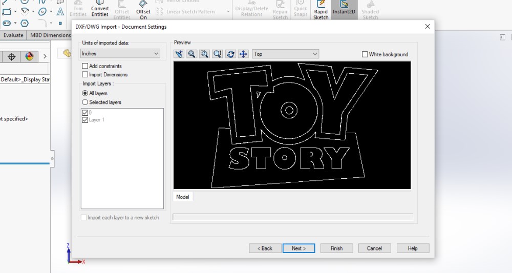
I decided the easiest way to get started would be to convert the raster logo to vector line and import those lines into SOLIDWORKS.
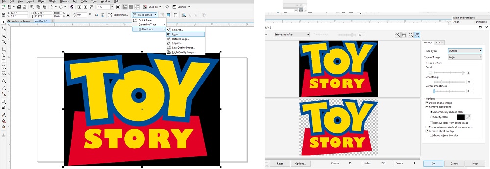
I found a high res image online and pasted it into Corel Draw. Then I used the Trace tool to trace the primary shapes.
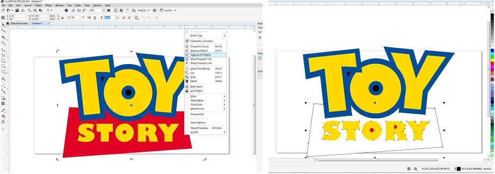
Once vectorized, I removed the fill and added a stroke to the outside of eash shape.
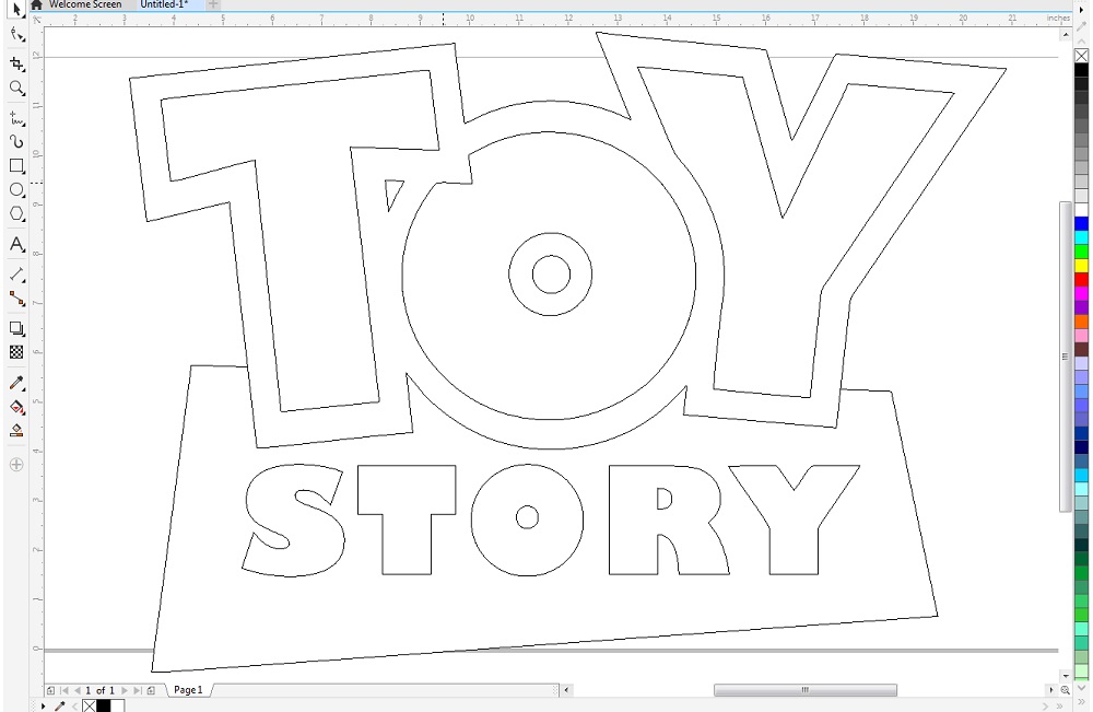
Finally, I made sure there were no duplicate lines before I exported to .DXF.
Using Vector Lines in SOLIDWORKS
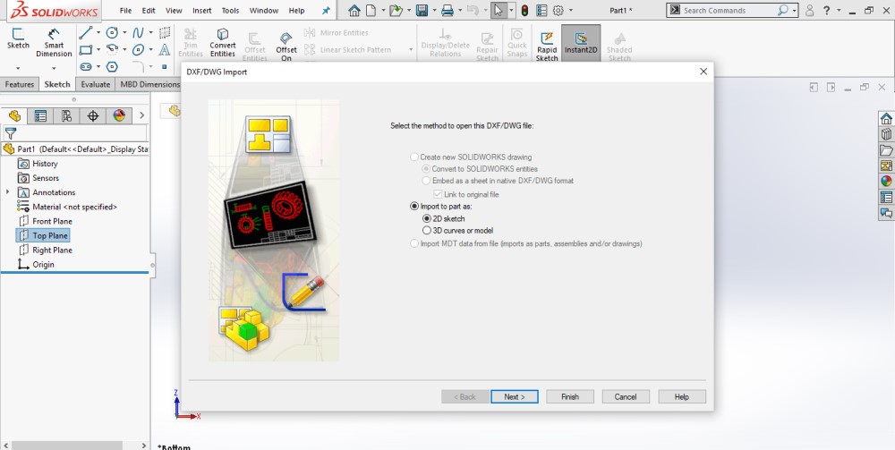
SOLIDWORKS has a handy import tool for DXF files. To use the import tool first select the PLANE the lines will be imported to.
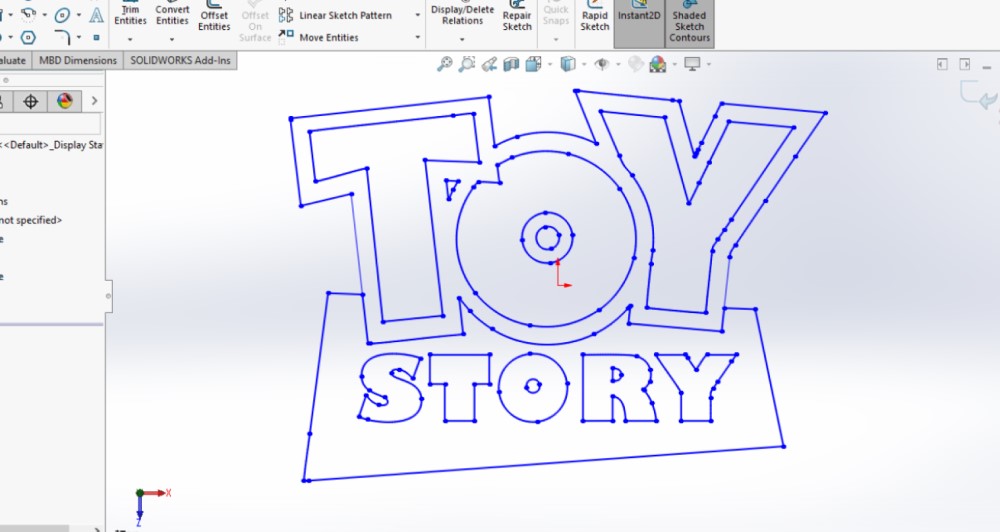
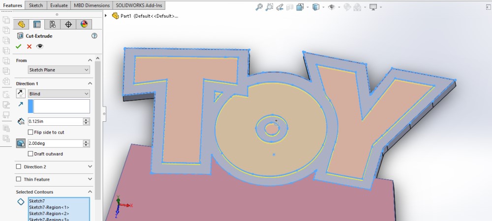
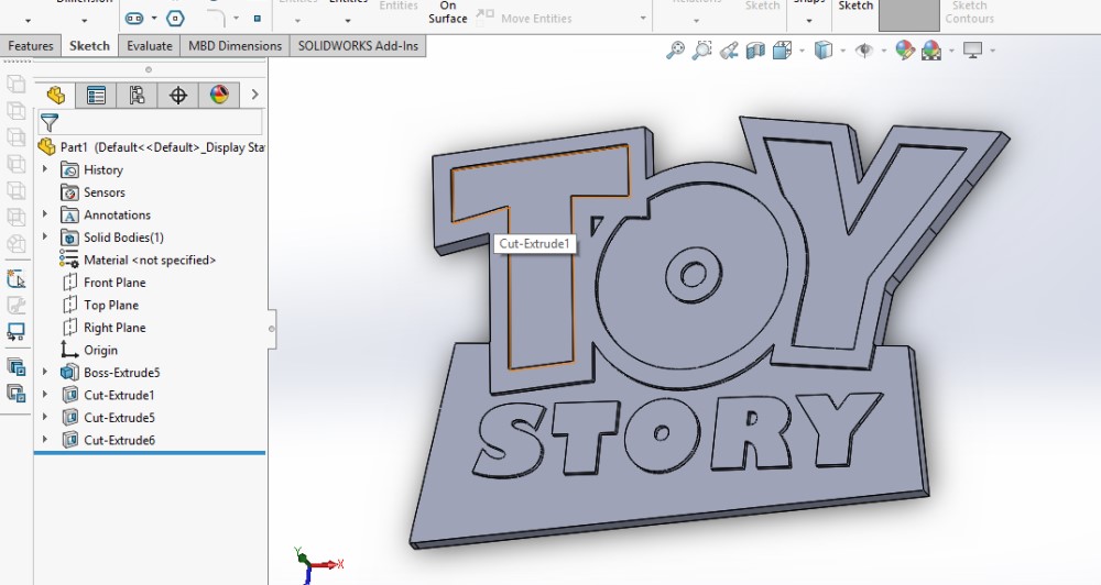
Each feature of the model was illulated to its own layer. For instance, the border around toy is going to be extruded more than everything else. To do this I imported the lines for only the boarder as one Sketch. Then, I imported the outline of the entire logo as a second sketch. Finally, I imported the lines for STORY as a third layer.
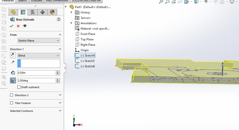
Each SKETCH was then extruded starting with the outline. Since I am making amold I used the Draft option to make the walls of the model angle in 2 degrees. This will help with demolding.
CAM for Mold Making
SOLIDWORKS has a really nice mold making feature that allows you to build the positive and negative molds in SOLIDWORKS. After some reading it looks like Roland’s SRP player also has a simple way of doing this in the CAM software.
2.5D Milling vs. 3D Milling
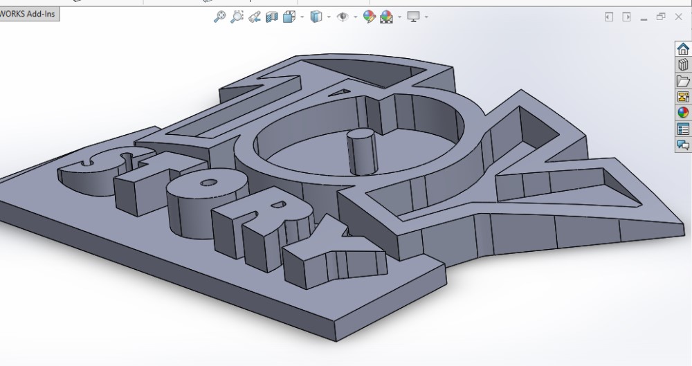
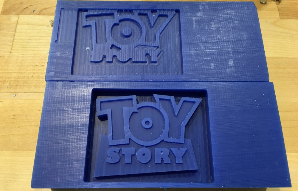
It was brought to my attention after completing this project that is more of 2.5D milling/model. This means that it isn’t really fully utilizing the 3 axis of the mill because all three axis never work in tandem at the same time. Below you can see how I shifted the model to make the milling process truly 3D and require the mill to move in the X/Y/Z axis all at the same time during the finishing cut.
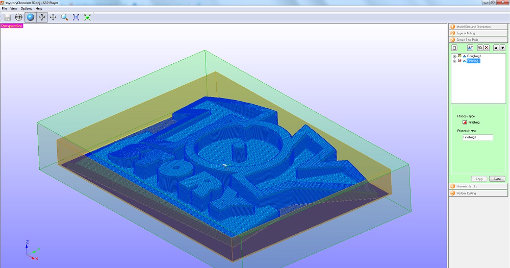
Here you can see how I adjusted the model so the face of it is arched with the center higher and the sides lower.
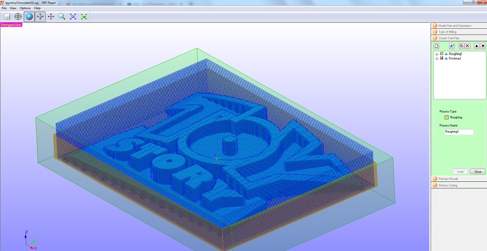
This is the roughing pass. The roughing pass is meant to remove material quickly and only leave a little material for the finishing pass. During the roughing pass the bit moved down in the Z axis and cuts an entire layer before moving down to the next layer and cutting.
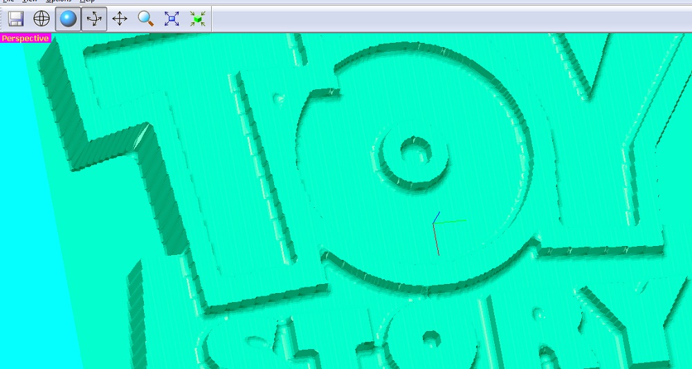
The finishing pass actually mills along the contours of the model, moving in all three axis.
SRP Player
SRP Player in my opinion is very polar. Some things are obvious and easy to follow but there are a few things that have no explination.
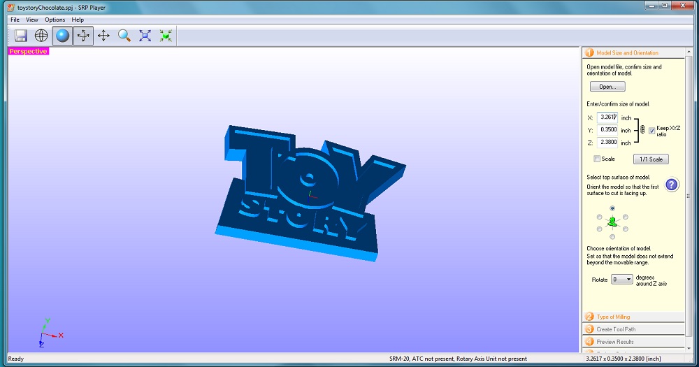
- To start the .STL file is loaded into the program when the program opens. I input the correct size that matched the SOLIDWORKS size. Then, I rotated the model to the Z axis was pointed up and the correct face of the model was pointed up with the Z.

- The TYPE OF MILLING settings allow you to specify the types roughing and finishing passes and the associated settings. Since this project has mostly flat surfaces and no rounded edges I picked all the quickest settings.
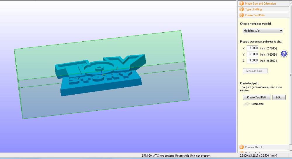
- CREATE TOOL PATHS is where you specify the workpiece size. There is a minimum size on each side to ensure that the piece is big enough to hold the model.
Once the size is defined by pressing CREATE TOOL PATH button creates the finishing and roughing tool paths based on the settings in the previous step.
Once the tool path is created all the settings can be seen and adjusted by clicking the EDIT button.
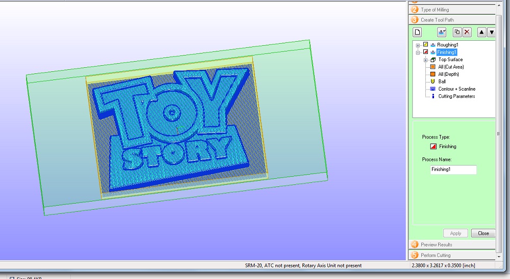
I double checked that the 1/8” bit was used for the rough cut and the 1/16” bit was used for the finishing cut.
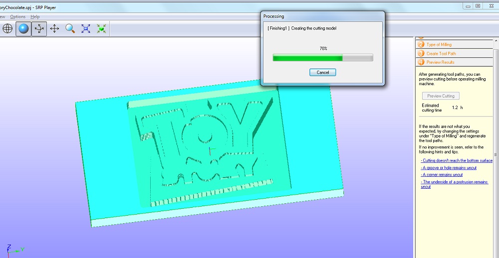
- PREVIEW CUT estimates a time for the cut. It also allows you to confirm that all the tiny holes and areas are cut by the bits selected for the cuts.
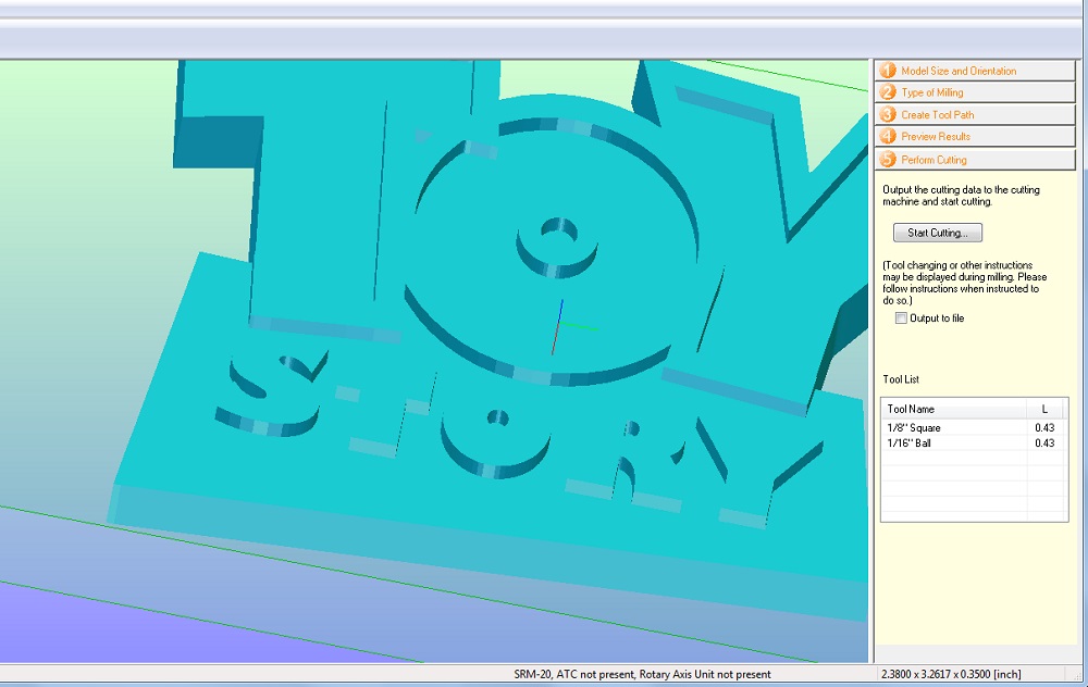
Before the moving on to pressing the START CUTTING button in step 5 the cnc mill has to be setup. Once this button is pushed the machine will use the current X/Y/Z zero settings.
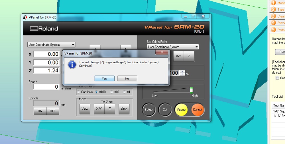
In the VPanel for SRM-20 I set the X/Y/Z origin for the wax block I was going to be cutting.
I forgot that the program automatically cuts from the center of the model. You can see the top block the model is shifted because I set it up like it was going to cut from the bottom left corner. The second block I made the X/Y origin centered on the block of wax.
Testing the limits of a 3 Axis Mill
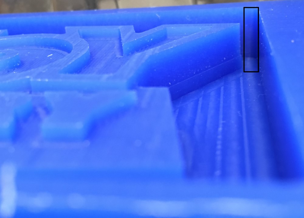
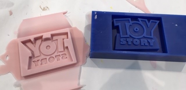
This model might look simple but it actually tests the limits of the 3 axis mill. A 2 degree angle on the side of a model is a very steep angle for the mill to cut. The mill cuts 3D objects by making small movements in the x or y axis and the z axis. This creates tiny stair steps of cuts. The goal is to dial in the mill and finishing cut so the stair steps of layers is undetectable. I’m really excited that the model edge came out so clean and still has the 2 degree angle. I’m making my mold from silicone and technically doesn’t need the 2 degree draft, but I want to eventually make the mold from vacuum form plastic. Since molds that are vacuum formed are stiff the draft will become important to allow the brittle chocolate to release from the mold.
Making the Mold
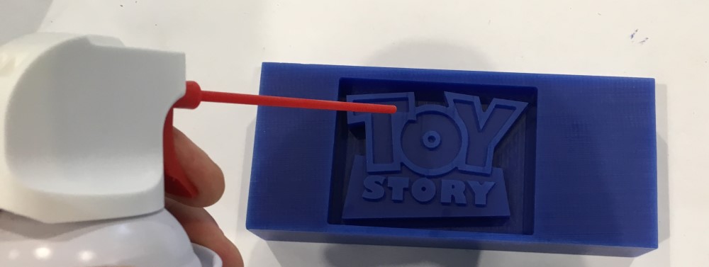
I used some compressed air to blow out the mold for starting the silicone mold process. The compressed air helps remove any dust or wax shaving from the small areas that I can’t reach by brush. Also, the compressed air is clean and if I use my a brush I might be contaminating the surface that will transfer to the mold.
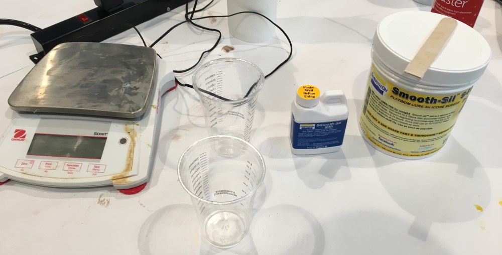
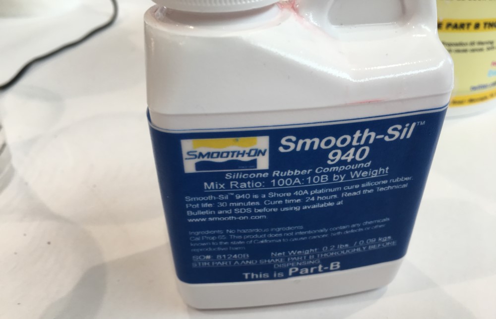
I’m using the Smooth-Sil 940 Smooth-On product because I wanted to create a food safe mold for chocolate. The ratio is supposed to 100A:10B
All mold making silicones are not created equally. Food grade silicone is actually monitored by the FDA. This helps ensure that there are no bad byproducts that would be harmful if digested. The is also medical grade silicone that has additional requirement.
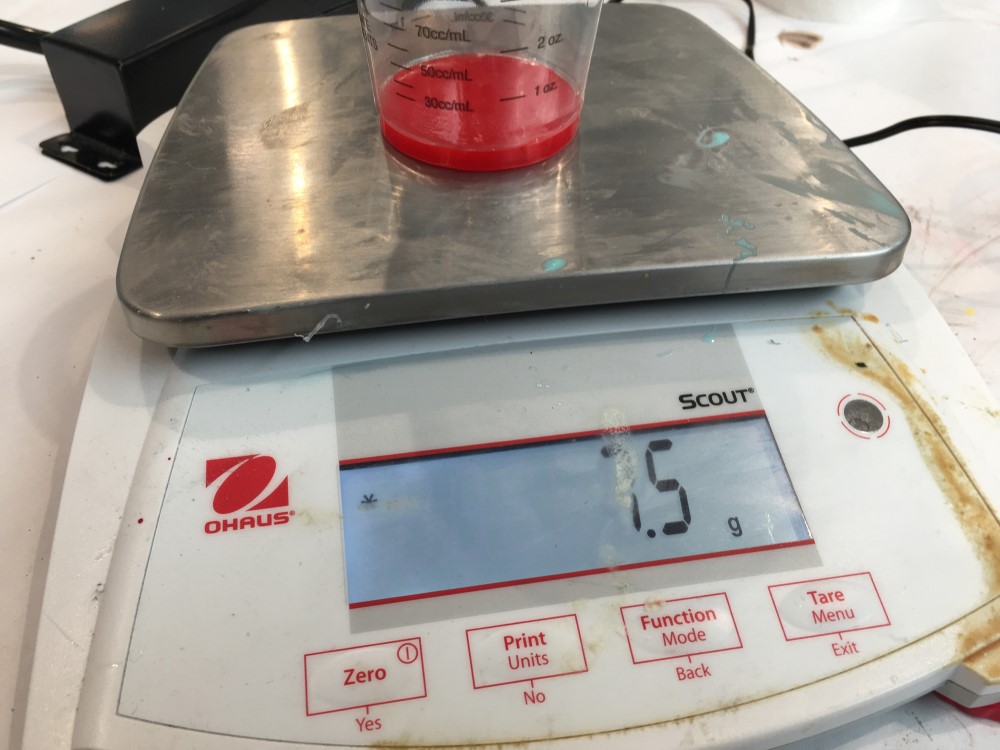
I started thinking I would mis 7.5B to 75 A but it didn’t look like enough.
I increase to 150A to 15B
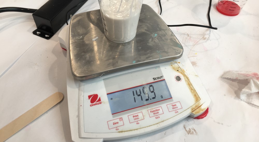
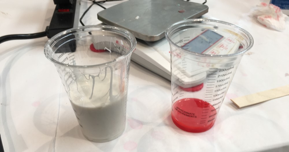

I poured the thinnest (PartB) into part A and double checked it on the scale to ensure I didn’t lose too much material to the measuring cup.
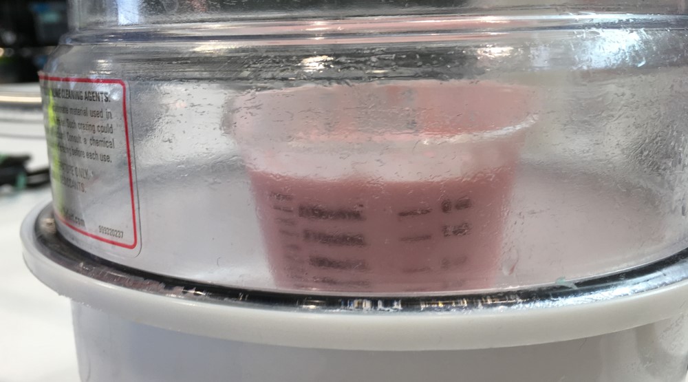
Once mixed together for a minute or two I put the mixture into a vacuum chamber to pull all the bubbles out. I was suprised to see how much the silicone expands in a vacuum. Luckily, my cup with big enough to hold the mixture. I initially degassed the mixture in the cup before pouring it because the mold was too big for our tiny vacuum chamber. Now, after seeing how much the mixture expanded during the degassing it would not work to degas in the wax mold. If degassed in the wax mold the mixture would expand out of the mold and make a huge mess.
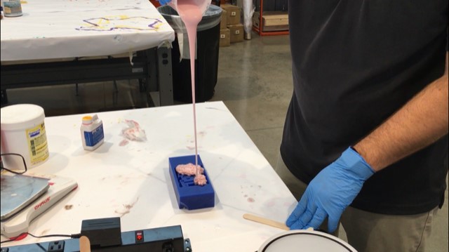
I poured the silicone into the wax mold in a thin bead from high above the wax and the mold came out perfect after it sat for about 6-8 hours.