5. Electronics production
ISP-ATtiny45
This week I learnt how to realize and program an ISP-ATtiny45. An ISP is an in-system programmer that allows to program the microcontrollers on other boards.
I learnt that in circuits the power enters in VCC, respectively moves to the pins of a microcontroller and dissipates in GND. I milled FR1 sheets, soldered them to electrical components and programmed my board.
Outline and Traces
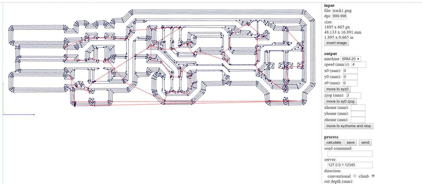
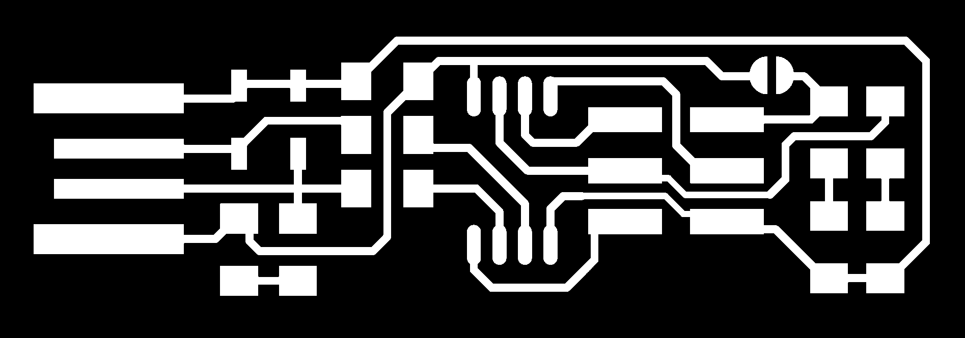
1st step: I started downloading traces and outline images of ISP-ATtiny45 to convert them in milling files with Fab Modules. I uploaded the files at the foot of the page.
2nd step: Once at a time, I uploaded them in fab modules “input”, selected the Roland SRM-20 for the “output”, and the specific size of milling diameter in “process”;
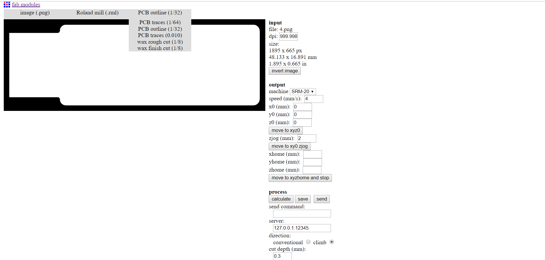
3d step: Then, Respectively, I set the other necessary parameters of milling, so origin point, depth and offset; I used the “calculate” command and sent the files to the machine.
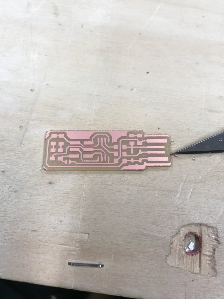
Milling
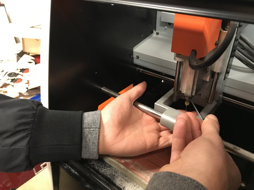
1st step: I attached my FR1 sheet to an mdf piece, and attached both to the Roland SRM-20 milling plane of the machine to protect it. Once a time I changed blades too, carefully.
2nd step: I opened the file, defined origin points on command panel of the machine and started milling pushing “output” command in the machine’s software. I set the spindle at a speed of 168 rounds at second to cut the traces with a blade of 1/64, and the spindle ..
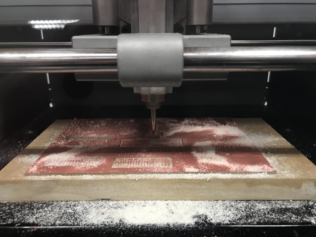
Then I removed deburrings.
I made more test to learn how to mill properly.
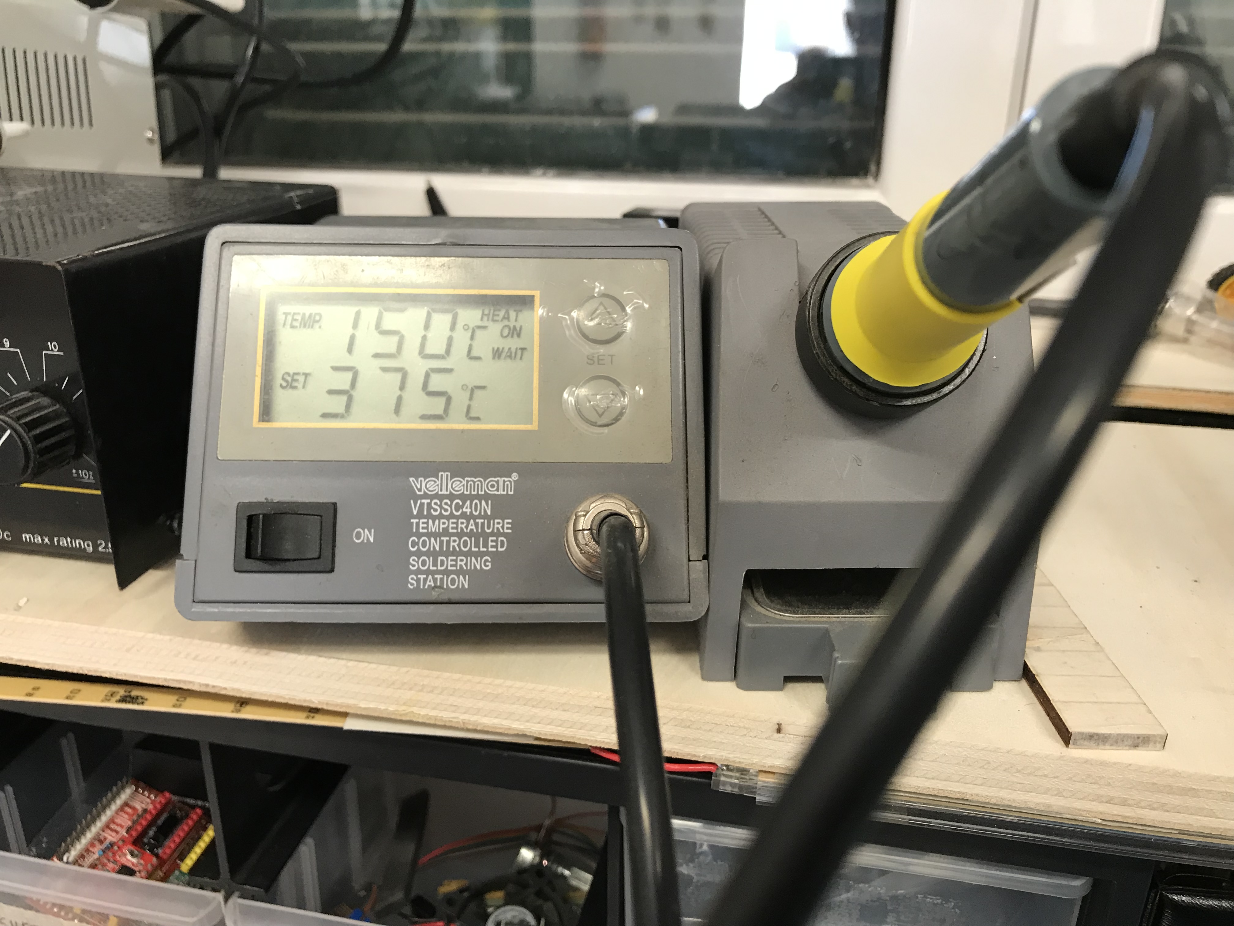
Soldering
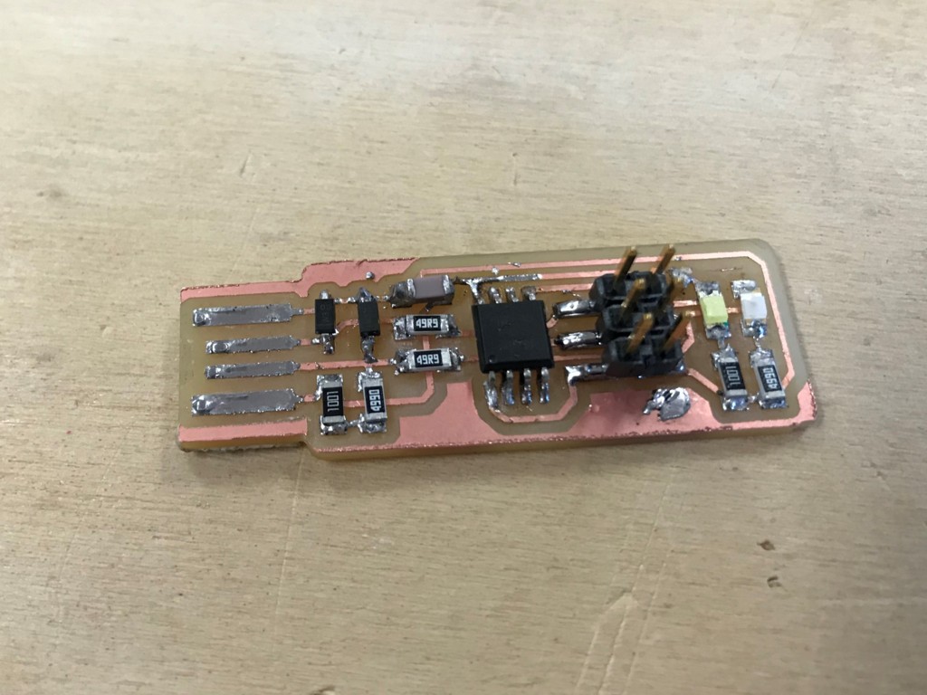
I soldered an Attiny45 with:
- 2x 1kΩ resistors
- 2x 499Ω resistors
- 2x 49Ω resistors
- 2x 3.3v zener diodes
- 1x red LED
- 1x green LED
- 1x 100nF capacitor
- 1x 2x3 pin header
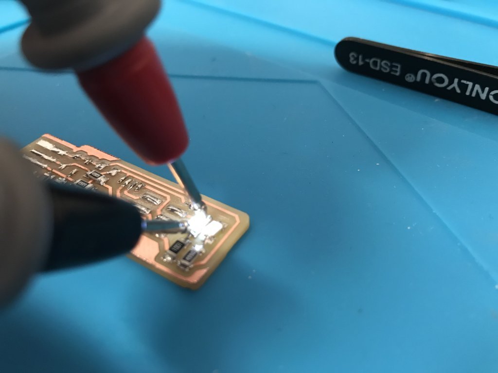
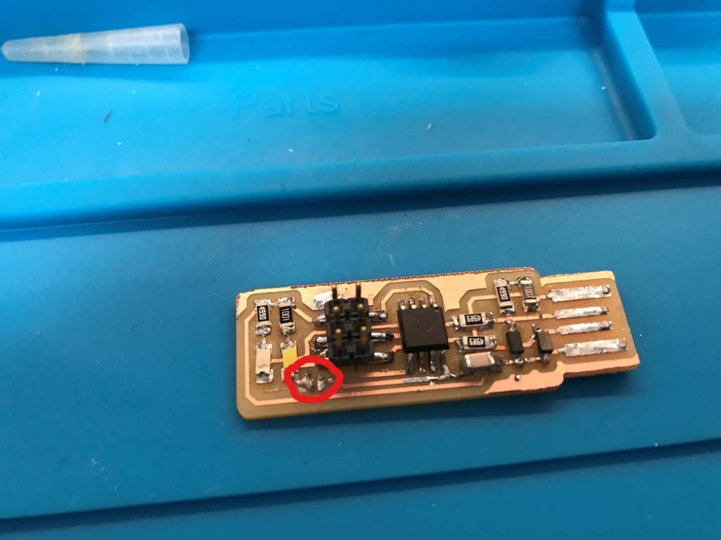
1st step: I covered my board with soldering paste to attract and so to direct properly melted tin; I started soldering my board to resistors and LEDs; then diodes, pins and the microcontroller.
I also connected the the default divided path in the ground just to program my board.
2nd step: I checked the soldering result adding power to the traces and measuring it by the sides of resistors and testing LEDs directions.
Enabling Attiny45 ISP as programmer
1st step: I installed necessary softwares to program my board on my Windows 10:
(I couldn’t install the new files of Brian’s guide so my instructor gave me other versions)
- avrdude
- GNU-make-3.81
- avr8-gnu-toolchain
- zadig-2.4
- fts-firmware-bdm-v1
- arduino-1.8.8
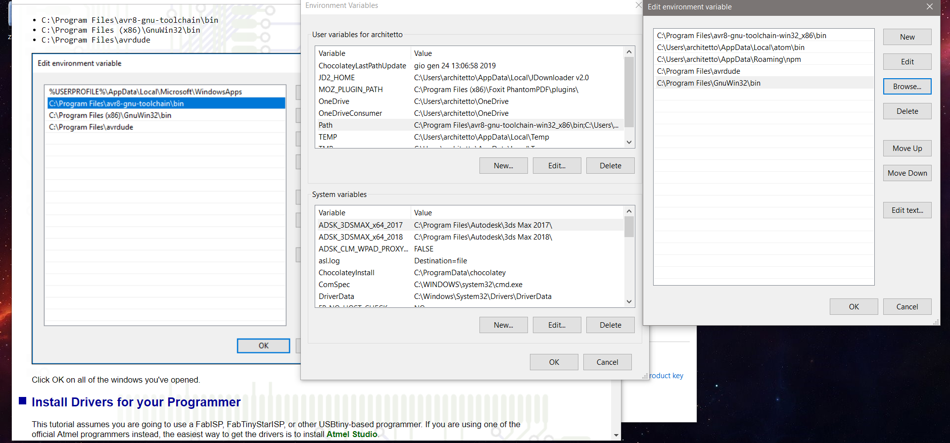
So I moved these files to my computer path:
“Control panel” > “System Advance Settings” > “Enviromental Variables” > “Path” > “Edit” > “Browse” .
Then I installed lisbusb-win32 driver using zadig-2.4.
2nd step: I connected the board to a FabAVR-ISP and connected them to my computer.
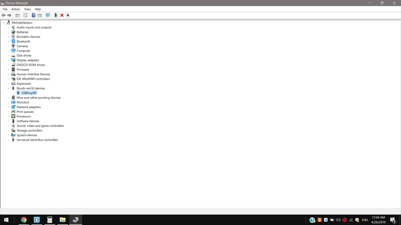
3rd I opened the Device Manager window to see if the FabISP is detected from my PC.
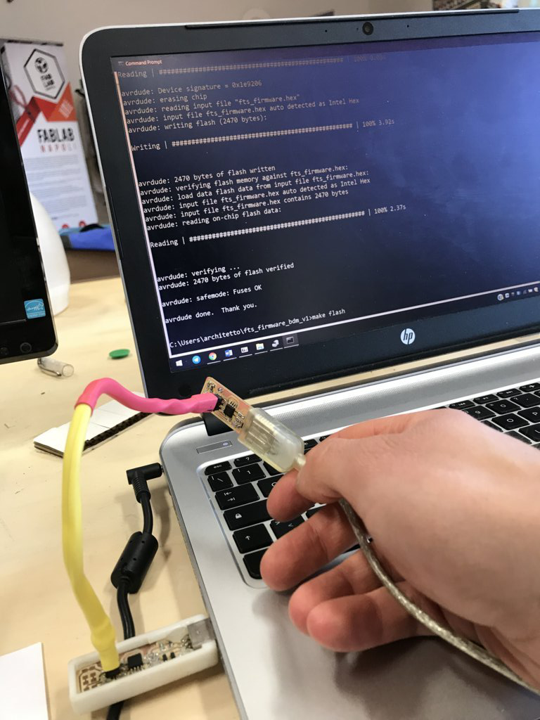
4th Into the Command Prompt I program my ATtiny45 running “make -v” then “avr-gcc -v” and after “make flash”.
C:\Users>make -v
GNU Make 3.81
......
This program built for i386-pc-mingw32
C:\Users>avr-gcc -v
Using built-in specs.
Reading specs from c:/program files/avr8-gnu-toolchain-win32_x86/bin/../lib/gcc/avr/5.4.0/device-specs/specs-avr2
COLLECT_GCC=avr-gcc
COLLECT_LTO_WRAPPER=c:/program\ files/avr8-gnu-toolchain-win32_x86/bin/../libexec/gcc/avr/5.4.0/lto-wrapper.exe
Target: avr
Configured with: /home/toolsbuild/workspace/avr8-gnu-toolchain/src/gcc/configure LDFLAGS=-L/home/toolsbuild/workspace/avr8-gnu-toolchain/avr8-gnu-toolchain-win32_x86-hostlibs/lib CPPFLAGS= --target=avr --host=i686-w64-mingw32 --build=x86_64-pc-linux-gnu --prefix=/home/toolsbuild/workspace/avr8-gnu-toolchain/avr8-gnu-toolchain-win32_x86 --libdir=/home/toolsbuild/workspace/avr8-gnu-toolchain/avr8-gnu-toolchain-win32_x86/lib --enable-languages=c,c++ --with-dwarf2 --enable-doc --disable-shared --disable-libada --disable-libssp --disable-nls --with-avrlibc=yes --with-mpfr=/home/toolsbuild/workspace/avr8-gnu-toolchain/avr8-gnu-toolchain-win32_x86-hostlibs --with-gmp=/home/toolsbuild/workspace/avr8-gnu-toolchain/avr8-gnu-toolchain-win32_x86-hostlibs --with-mpc=/home/toolsbuild/workspace/avr8-gnu-toolchain/avr8-gnu-toolchain-win32_x86-hostlibs --enable-win32-registry=avrtoolchain --with-pkgversion=AVR_8_bit_GNU_Toolchain_3.6.2_1759 --with-bugurl=http://www.atmel.com
Thread model: single
gcc version 5.4.0 (AVR_8_bit_GNU_Toolchain_3.6.2_1759)
C:\Users\fts_firmware_bdm_v1>make flash
avrdude -p attiny45 -c usbtiny -P usb -e \
                -U flash:w:fts_firmware.hex

avrdude: AVR device initialized and ready to accept instructions

Reading | ################################################## | 100% 0.03s
avrdude: Device signature = 0x1e9206
avrdude: erasing chip
avrdude: reading input file "fts_firmware.hex"
avrdude: input file fts_firmware.hex auto detected as Intel Hex
avrdude: writing flash (2470 bytes):

Writing | ################################################## | 100% 3.92s
avrdude: 2470 bytes of flash written
avrdude: verifying flash memory against fts_firmware.hex:
avrdude: load data flash data from input file fts_firmware.hex:
avrdude: input file fts_firmware.hex auto detected as Intel Hex
avrdude: input file fts_firmware.hex contains 2470 bytes
avrdude: reading on-chip flash data:

Reading | ################################################## | 100% 2.37s
avrdude: verifying ...
avrdude: 2470 bytes of flash verified

avrdude: safemode: Fuses OK

avrdude done.
avrdude done.
5th step: And finally, I disabled its reset mode removing the contact from the divided default traces and runt “make rstdisbl”.
C:\Users\architetto\fts_firmware_bdm_v1>make rstdisbl
avrdude -p attiny45 -c usbtiny -P usb \
                -U lfuse:w:0xE1:m -U hfuse:w:0x5D:m \
                -U efuse:w:0xFF:m

avrdude: AVR device initialized and ready to accept instructions

Reading | ################################################## | 100% 0.03s

avrdude: Device signature = 0x1e9206
avrdude: reading input file "0xE1"
avrdude: writing lfuse (1 bytes):

Writing | ################################################## | 100% 0.02s

avrdude: 1 bytes of lfuse written
avrdude: verifying lfuse memory against 0xE1:
avrdude: load data lfuse data from input file 0xE1:
avrdude: input file 0xE1 contains 1 bytes
avrdude: reading on-chip lfuse data:

Reading | ################################################## | 100% 0.01s

avrdude: verifying ...
avrdude: 1 bytes of lfuse verified
avrdude: reading input file "0x5D"
avrdude: writing hfuse (1 bytes):

Writing | ################################################## | 100% 0.02s

avrdude: 1 bytes of hfuse written
avrdude: verifying hfuse memory against 0x5D:
avrdude: load data hfuse data from input file 0x5D:
avrdude: input file 0x5D contains 1 bytes
avrdude: reading on-chip hfuse data:

Reading | ################################################## | 100% 0.01s

avrdude: verifying ...
avrdude: 1 bytes of hfuse verified
avrdude: reading input file "0xFF"
avrdude: writing efuse (1 bytes):

Writing | ################################################## | 100% 0.01s

avrdude: 1 bytes of efuse written
avrdude: verifying efuse memory against 0xFF:
avrdude: load data efuse data from input file 0xFF:
avrdude: input file 0xFF contains 1 bytes
avrdude: reading on-chip efuse data:

Reading | ################################################## | 100% 0.02s

avrdude: verifying ...
avrdude: 1 bytes of efuse verified

avrdude: safemode: Fuses OK

avrdude done.
Test
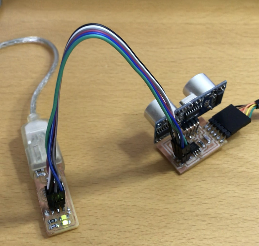
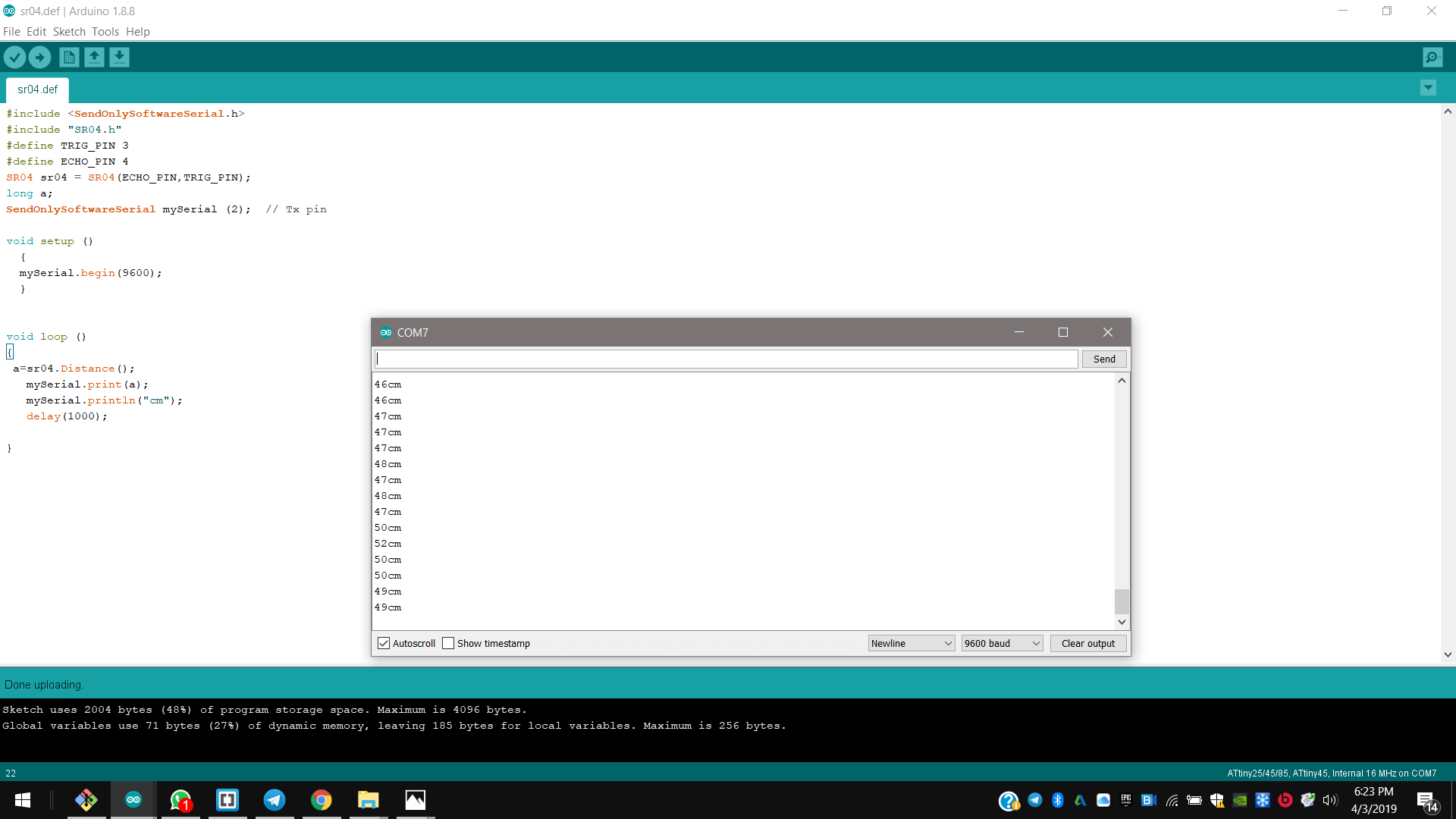
I tested it programming the board I made for the “output devices” week, to read a distance sensor by serial monitor. I connected my programmer to its isp MISO, MOSI, SCK, RST, VCC and GND, and I uploaded the “send only software serial” code, so just sending signals by RX pin.