Week6 Group Assignment: 3D Scanning and printing
Characterizing the machine
Zortrax M-200
For this week’s group assignment we had to characterize the specifications of our LDM 3D Printer - Zortrax M-200. The software that we used to generate Z-Code (closed gCode for Zortrax printers) was Z-Suite, online at Zortrax Site and send to the machine trought by SD card.
Check the design rules
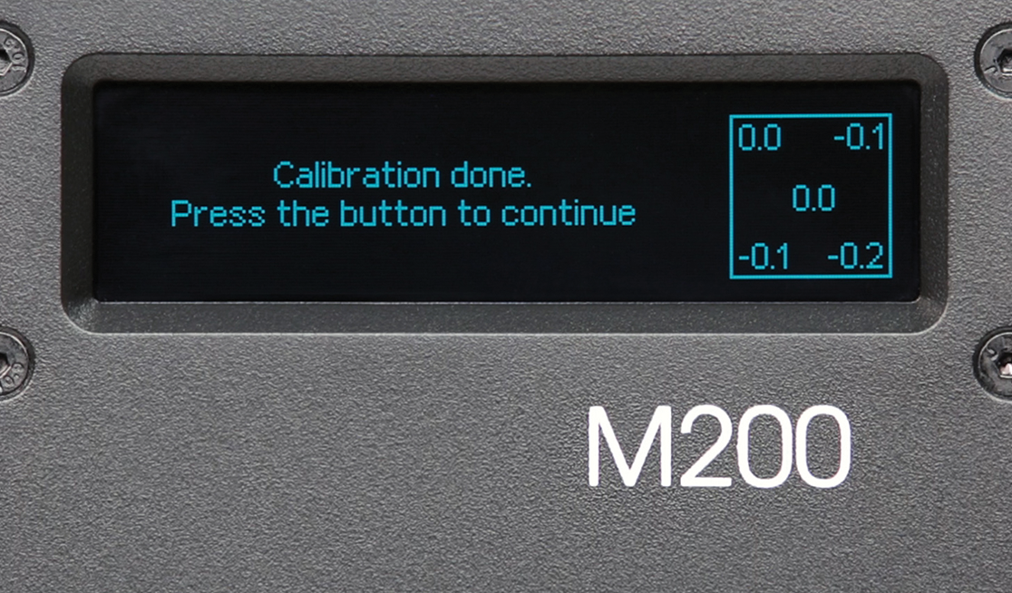
After guided Calibration process we have download some test files to caracterize our 3D printer.
XYZ 20mm Calibration Cube –> thing:1278865
Overhang Tester, 5 - 90 degrees –> thing:261317
TEST_1
Setup
- Tool: 3D Printer - LDM
- Model: Zortrax M-200 (200.0 (X) x 200.0 (Y) x 185.0 (Z Max) mm Working Area)
- Noozle: 1/64 (0.4mm)
- Materials: Z-ABS (ABS)
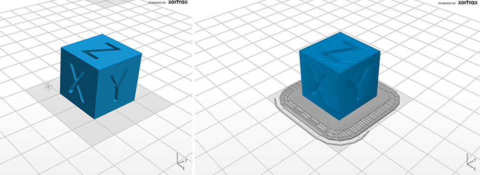
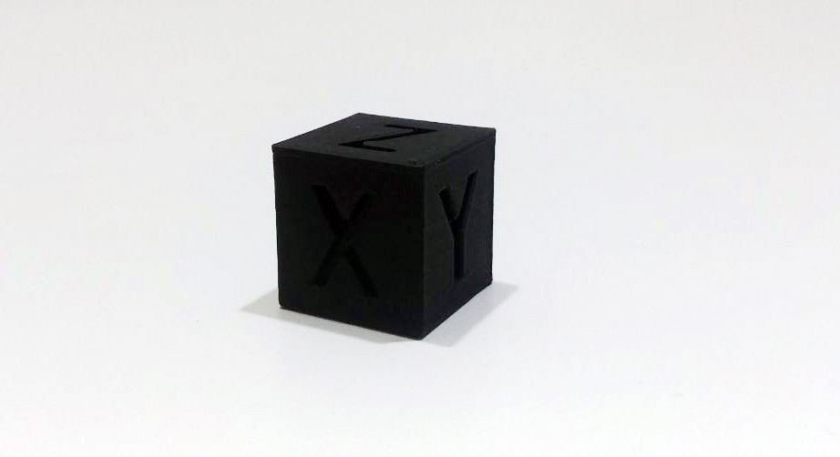
We did a “XYZ 20mm Calibration Cube” test using the downloaded file and prepare the Z-Code with this parameters:
Parameters
-
Application version: 2.7.1.0
- Estimated print time: 0h 39m
- Material: Z-ABS
- Material usage: 2.71m (6g)
- Printer: Zortrax M200
-
Profile: custom
- Support type: Editable
//no support needed for this model. I've no proceeded to generate them, but the follow parameters are default. - Support: 25°
- Gap XY: 0.28
- Spacing: 3.50
- Nozzle diameter: 0.4 mm
- Layer: 0.19 mm
- Quality: High
- Infill: 50%
- Fan speed: Auto
- Seam: Normal
- Outer contours: 0.00
- Holes: 0.00
- Surface layers Top: 7
- Surface layers Bottom: 5
- Support Lite: No
- Smart bridges: No
- Support type: Editable
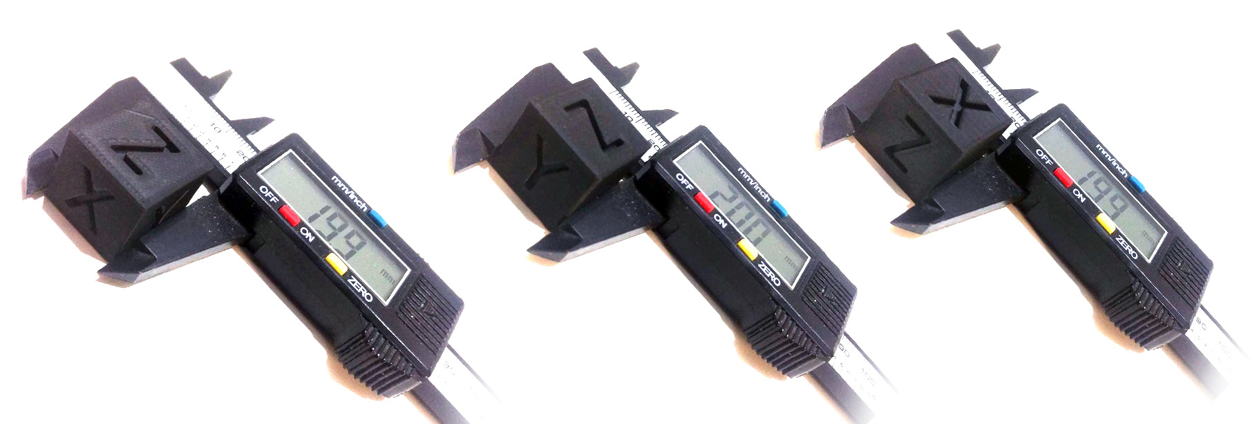
After waiting 39min… the original dimensions in the file are 20x20x20mm and after printed it we had removed the raft from the piece and measured every dimension with a caliper.
TEST_2
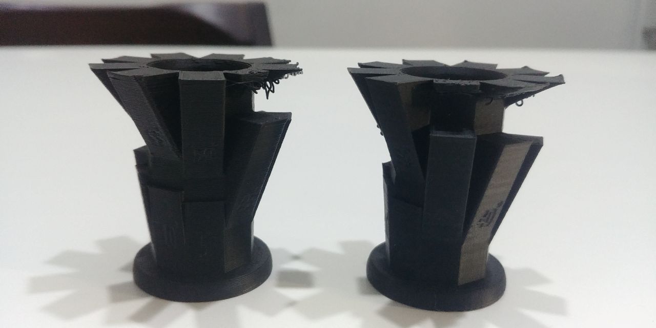
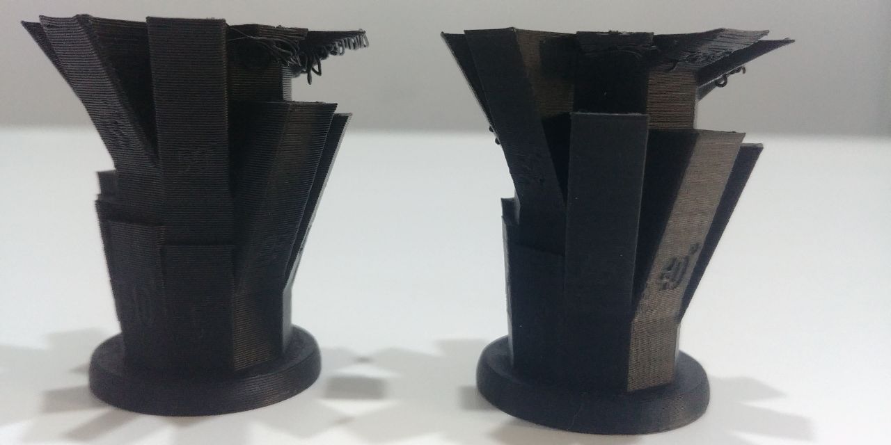
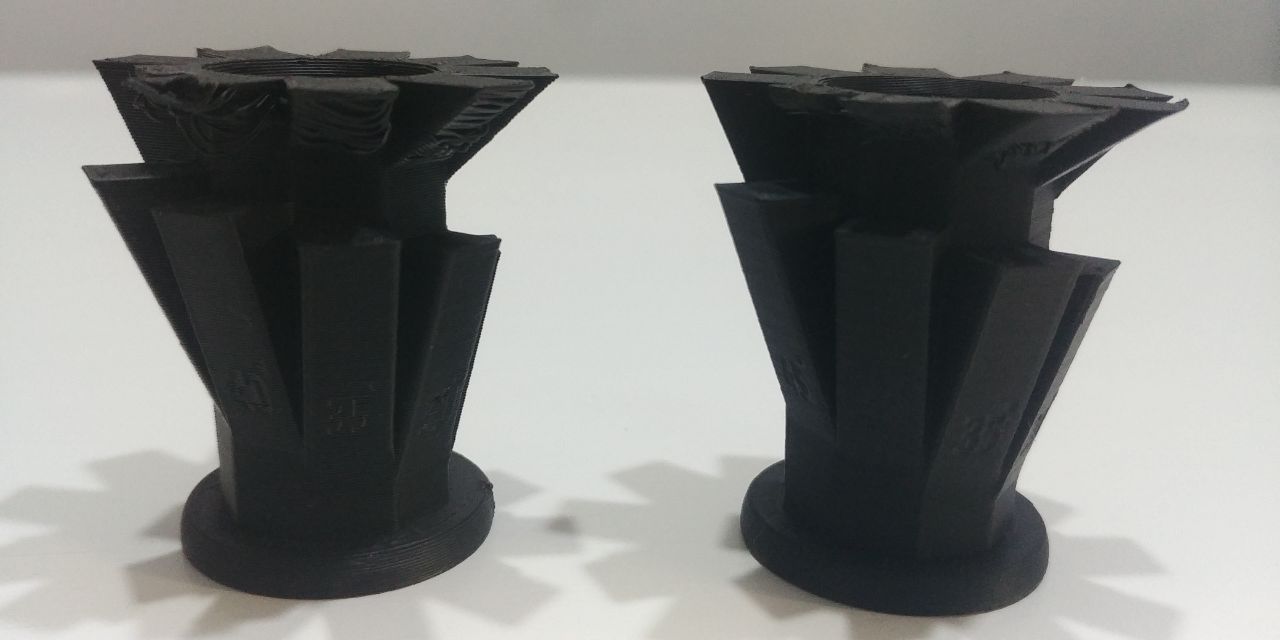
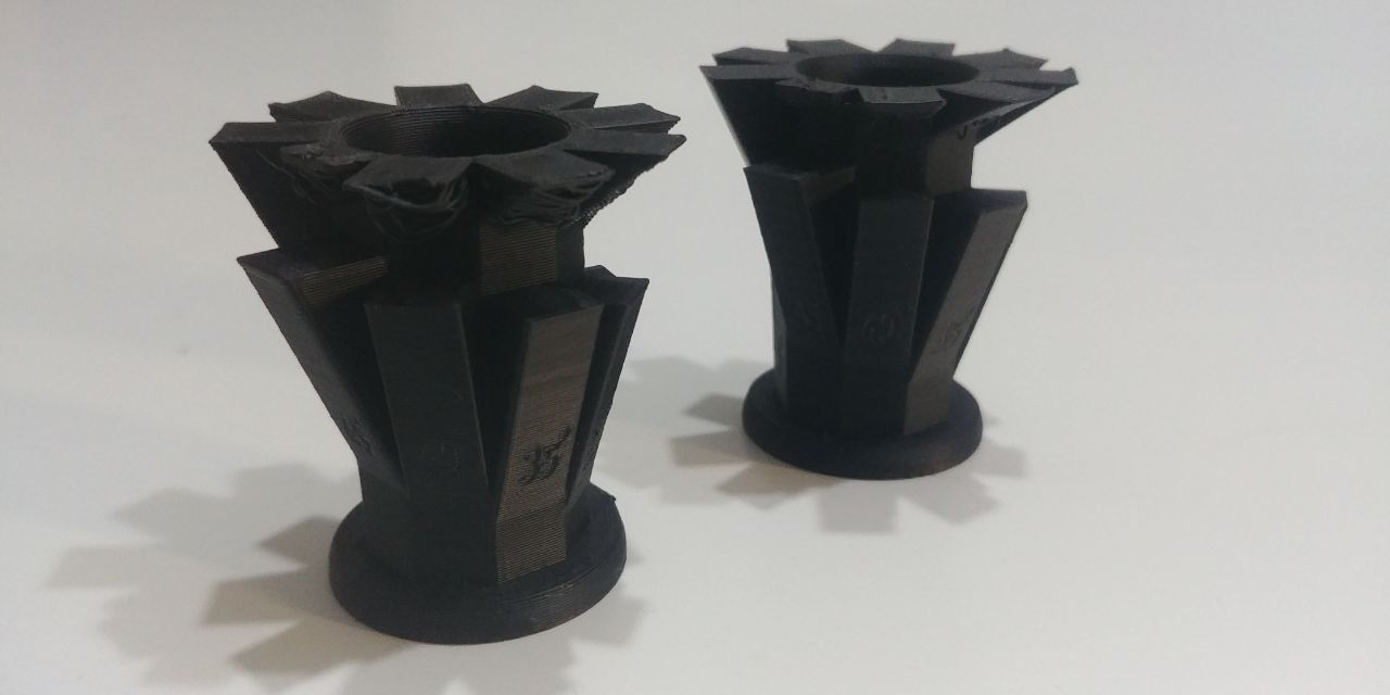
We did a “Overhangs no supported” test using the downloaded file and prepare two different Z-Codes to demostrate how the layer height can influence the no supported pice with different angles.
Parameters_1
- Application version: 2.7.1.0
- Estimated print time: 1h 33m
- Material usage: 6.06m (14g)
- Printer: Zortrax M200
- Profile: Last settings
- Support type: Editable
//no support needed for this model. I've no proceeded to generate them, but the follow parameters are default. - Support: 25°
- Gap XY: 0.28
- Spacing: 3.50
- Material: Z-ABS
- Nozzle diameter: 0.4 mm
- Layer: 0.29 mm
- Quality: High
- Infill: 50%
Parameters_2
- Application version: 2.7.1.0
- Estimated print time: 1h 33m
- Material usage: 6.06m (14g)
- Printer: Zortrax M200
- Profile: Last settings
- Support type: Editable
//no support needed for this model. I've no proceeded to generate them, but the follow parameters are default. - Support: 25°
- Gap XY: 0.28
- Spacing: 3.50
- Material: Z-ABS
- Nozzle diameter: 0.4 mm
- Layer: 0.14 mm
- Quality: High
- Infill: 50%
In the following image you can see what we had described above.
We had make another test designing a simple 10mm cilinder and a base with four holes: the first hole with same diameter of the cilinder; the second with 0.05mm offset (diam. 10.1mm); the thirth with 0.1mm offset (diam. 10.2mm); the fourth hole with 0.15mm offset (diam. 10.3mm) is resulted the best choice for assembly cilynder and hole without game between.