3. Computer Aided design
Final Project model
from Rhinoceros v.5
Usually I use Rhino and Grasshopper in my 3D Modeling workflow. I started from a 3D model of a few months ago, made entirely with Rhinoceros.
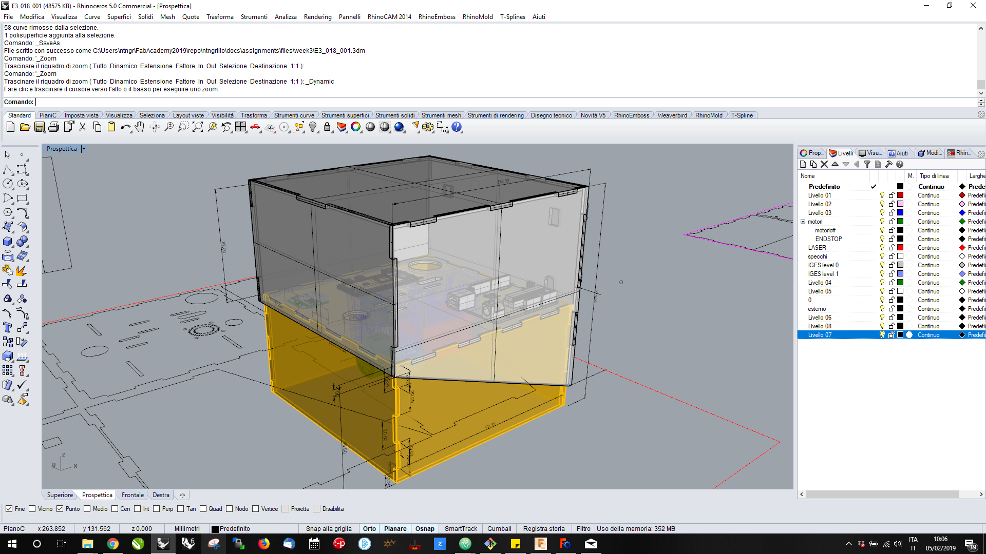
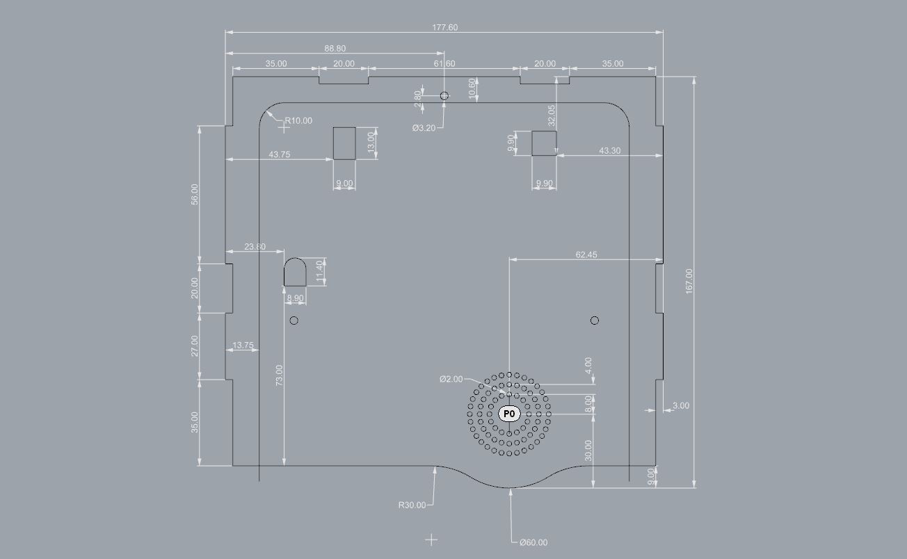
I’ve design the necessary panels directly in 2D using Rhinoceros basic level commands; in the following steps I show you the rear panel construction:
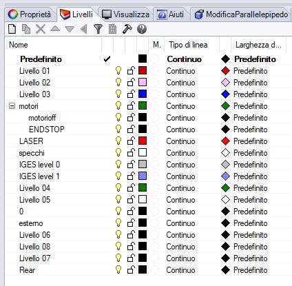
- Create new Layer running _Layer command to the prompt and add newone;
- Rename the Layer to remember the draw you will make in; I named mine Rear
- Run _Rectangle command than input 167.00 x 177.60 mm to make the rectangle (remember: in Rhino the decimal separator is the point “.” and the coordinate separator is th comma “,”);
- Select the created rectangle and _Explode it;
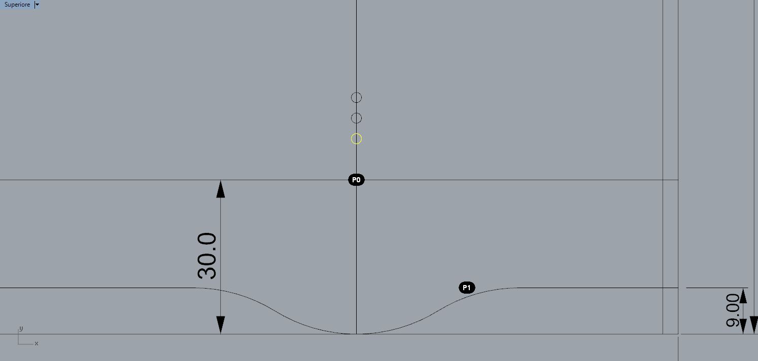
- now you can make the refences guideline offsetting the boundary lines through _Offset command;
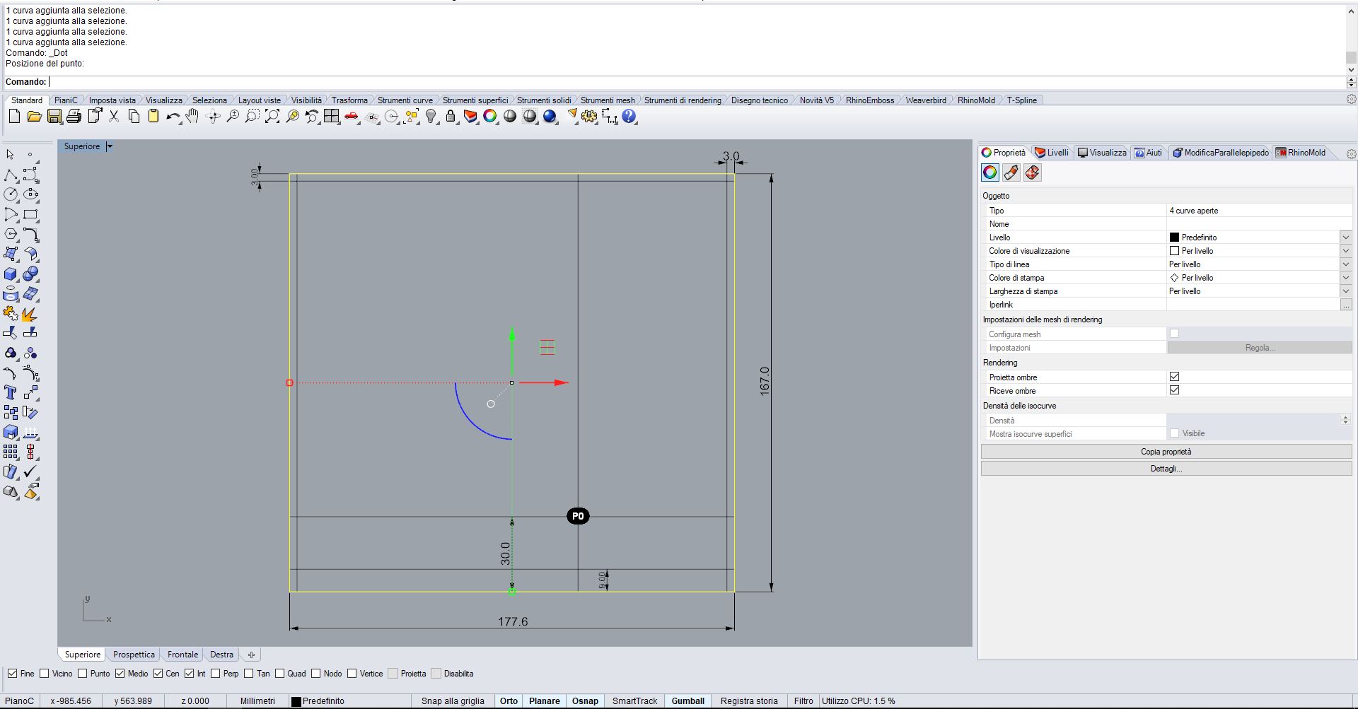
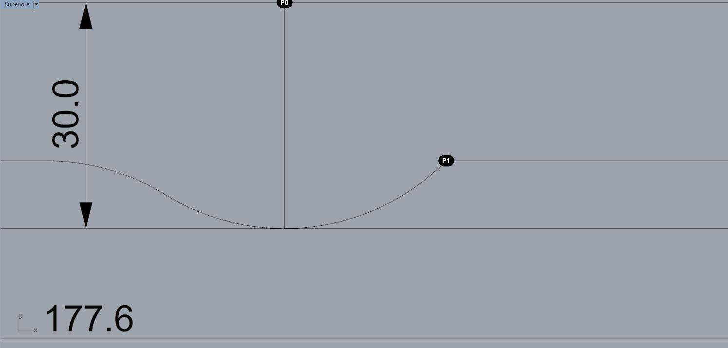
- Point in P0 and run _Circle to make a 30mm radius Circle;
- well, selecting the just created circle and the second horizontal line from the bottom, run the _Trim command and touch the segments you want to remove;
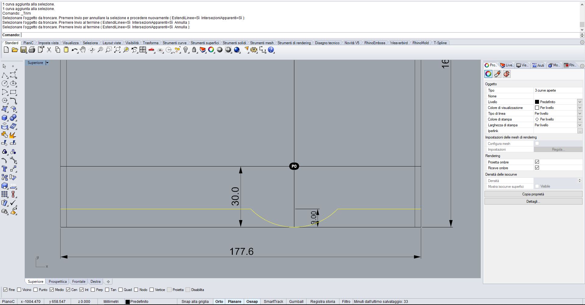
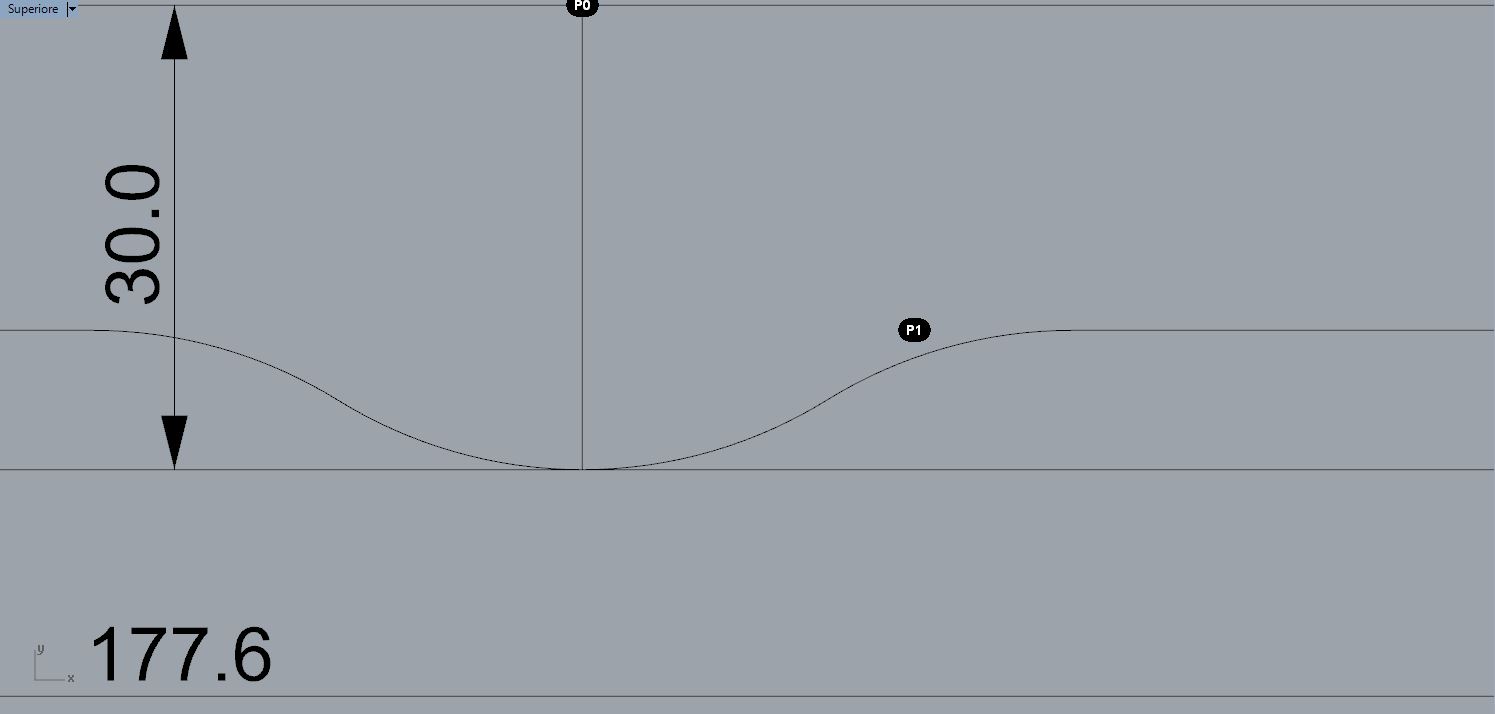
- run _Fillet and commit 30 as radius dimension to make a radius fillet between the two lines near P1 (angular point) selecting the 1st and 2nd line that touch the mentioned point;
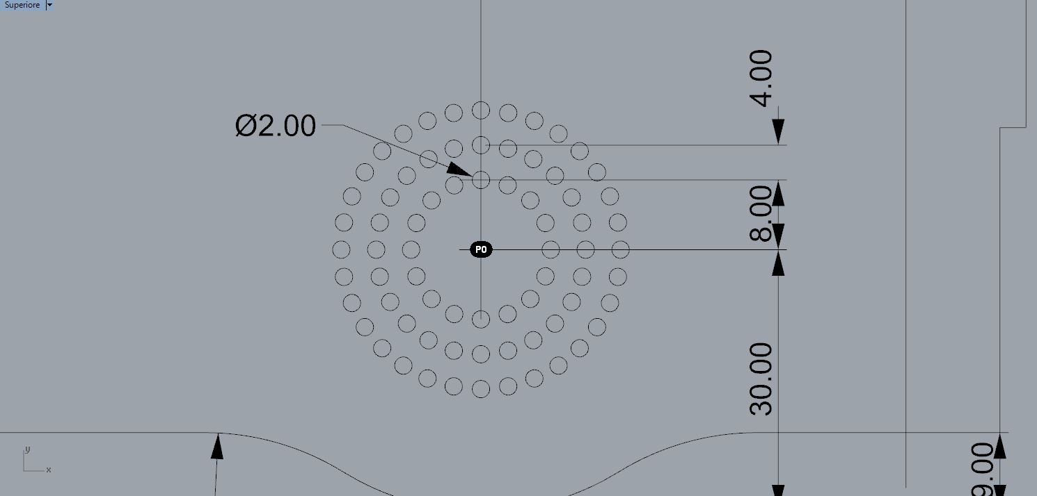
- make a circle in P0 with 2mm diameter, than _Move it for 8mm, than _Copy it two times with a 4mm step;
- create an _ArrayPolar of the 1st circle pointing the center of the array in P0 with 16 items; than repeat for the 2nd circle but with 24 items, and the third with 32 items.
Now you have all the general knowledge to continue the work following sketch below:
rendered in KeyShot v.6
With KeyShotVR I’ve made a photorealistic, touch-enabled, 3D rendered image, wich can be displayed in every web browser supporting HTML5.
Note
The content below can be viewed by using mouse or finger on touch-enabled devices and does not require a browser plugin to work. Furthermore, KeyShotVR is not WebGL based and is therefore able to deliver the highest quality possible across the widest range of devices.
FreeCAD
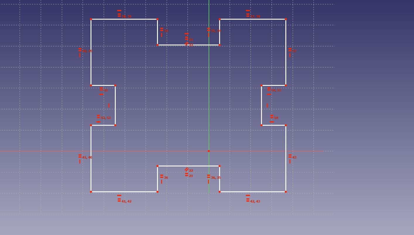
Evaluating what were the critical issues to be solved in the model, I’ve remodeled it by using FreeCAD.
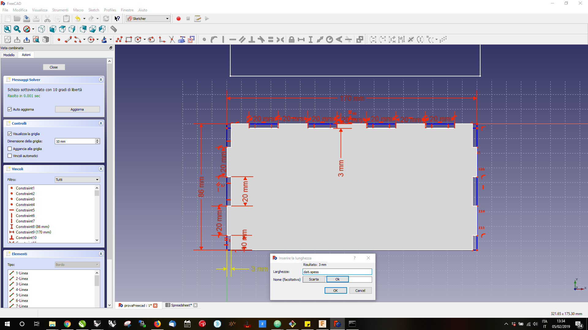
I set constraints in the sketch and I used a parameter related to the thickness of the material to design the joints. The thickness parameter is connected through a spreadsheet and the syntax to recall the data is really simple:
syntax
in the dimension input field you can choose to insert a number or a function.
{spreadsheet_name}.{cell_name}
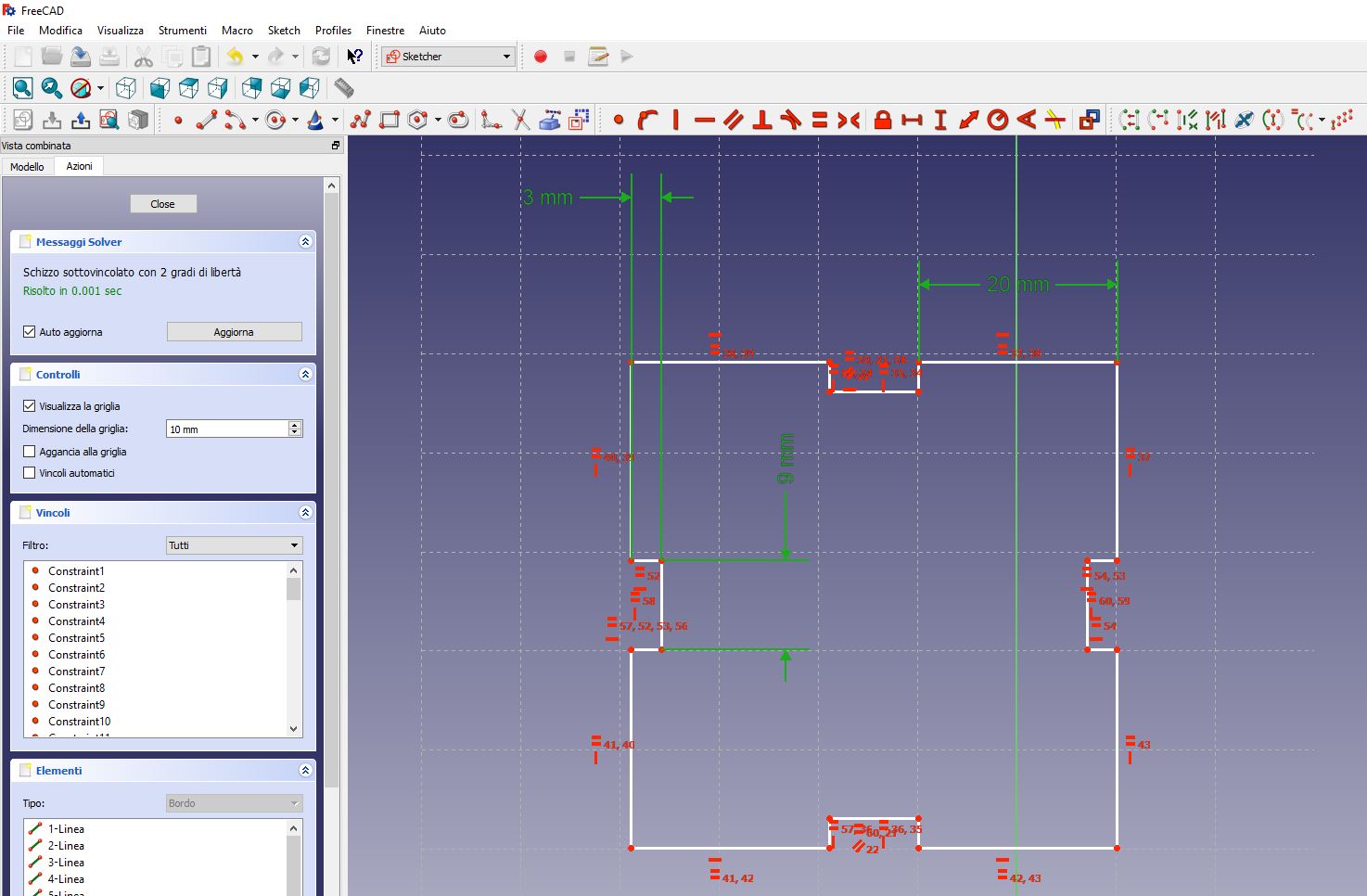
Expliciting the parametric syntax you can design a 2D parametric model as follows:
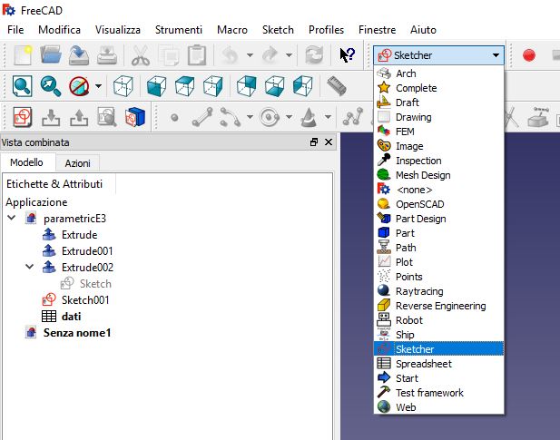
- Create New Project and select Sketcher workbench;
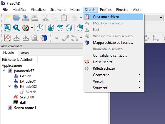
- Add new sketch selecting it from Tools > Create new Sketch, than select a plane to work on;
- Start drawing a sketch widhout dimensions, like lines, circle, rectangle, …;
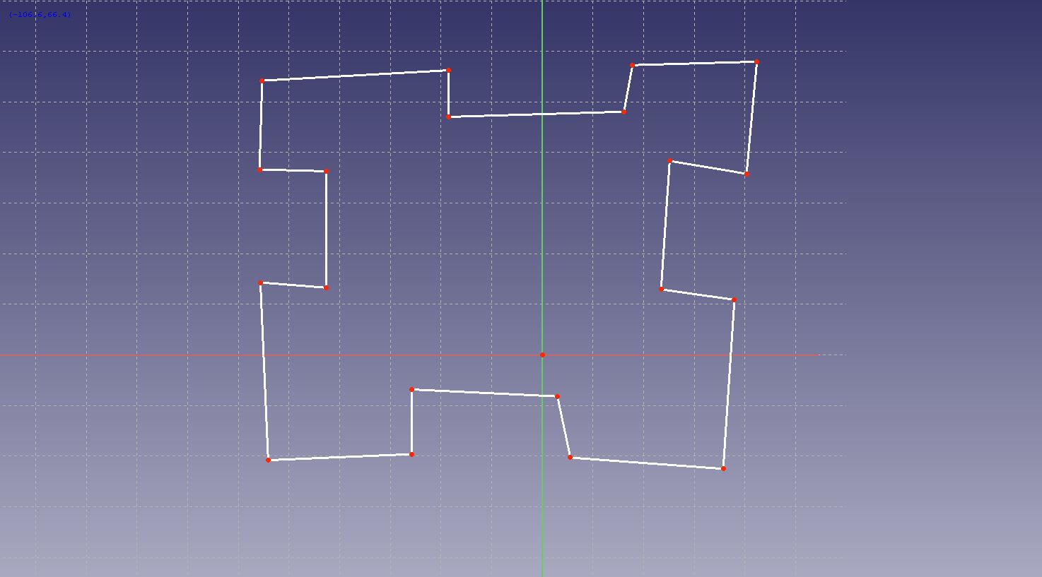
- than set constrains to the sketch to create parallelisms, intersections;
- now you can set fix or variables dimensions. Following the previous implicit syntax
{spreadsheet_name}.{cell_name}you can set parametric dimensions using a linked spreadsheet; - well, first of all you must create a spreadsheet. Set the spreadsheet workbench, than go to Spreadsheet > Create new spreadsheet and rename it to data;
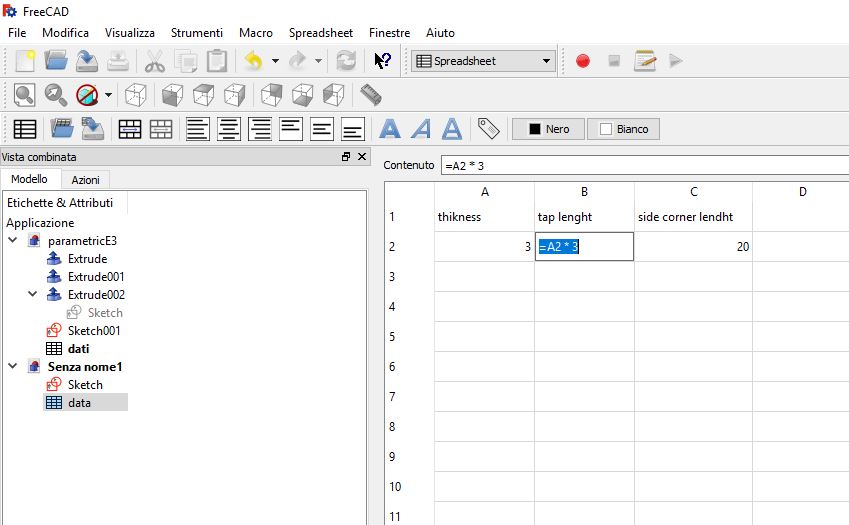
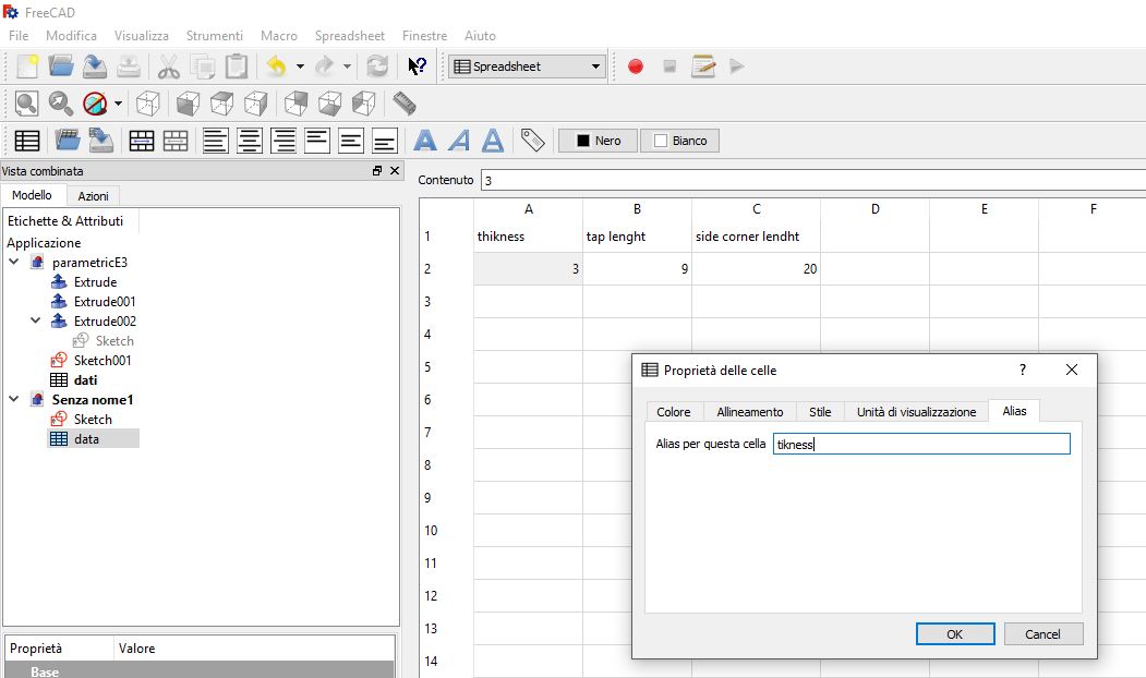
- compile the spreadsheet with cells that you want use into the sketch, but remember that the value cells must be have an Alias;
- Now setting the Horizontal/Vertical Dimension Constrains, you can recall the data stored in the spreadsheet.
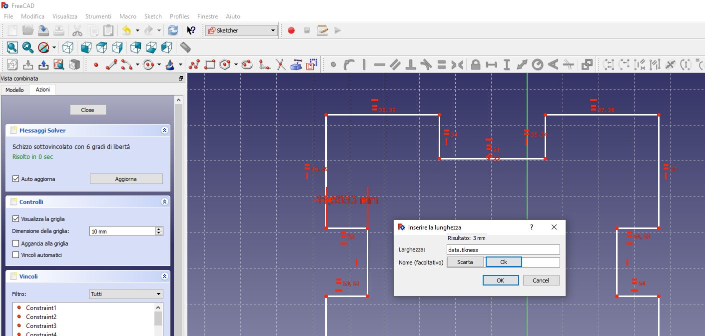
- Now you are ready to design your parametric Sketch.
Once design a right sketch I’ve made a 3D model extruding a sketch to a distance.
Extra
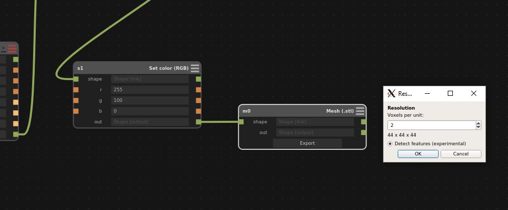
Antimony
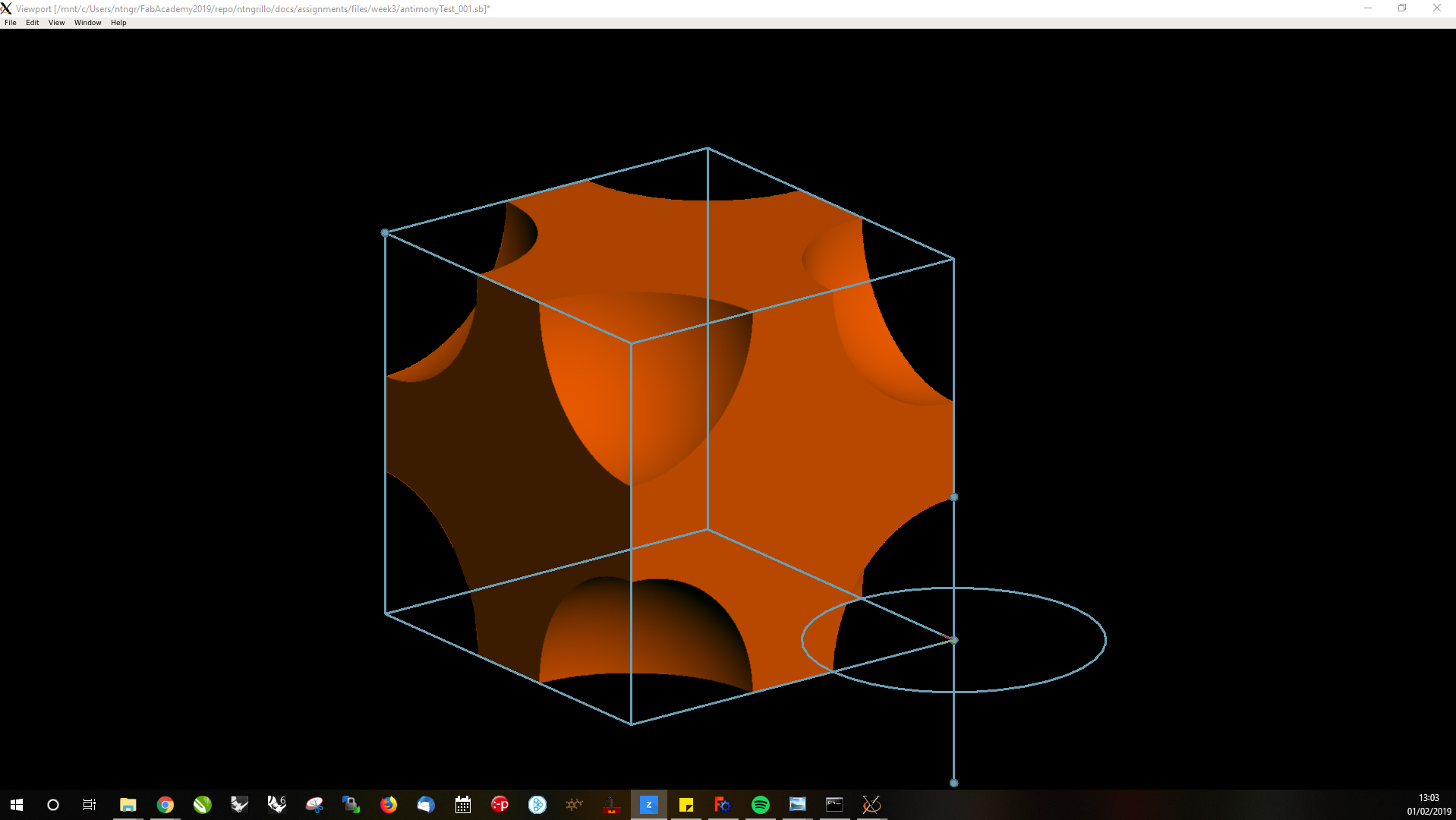
This week I’m experimenting with Antimony and CSG modeling. Made a first definition, by using the visual scripting of Antimony, I moved to file export section: Antimony can export in .stl (using voxels) and height maps in .PNG (usually useful for the realization of 3D-Engrave with laser). During the exportation in .stl I had to choose the three-dimensional matrix to describe the geometry modeled in the software, torught Voxels per Unit Input;
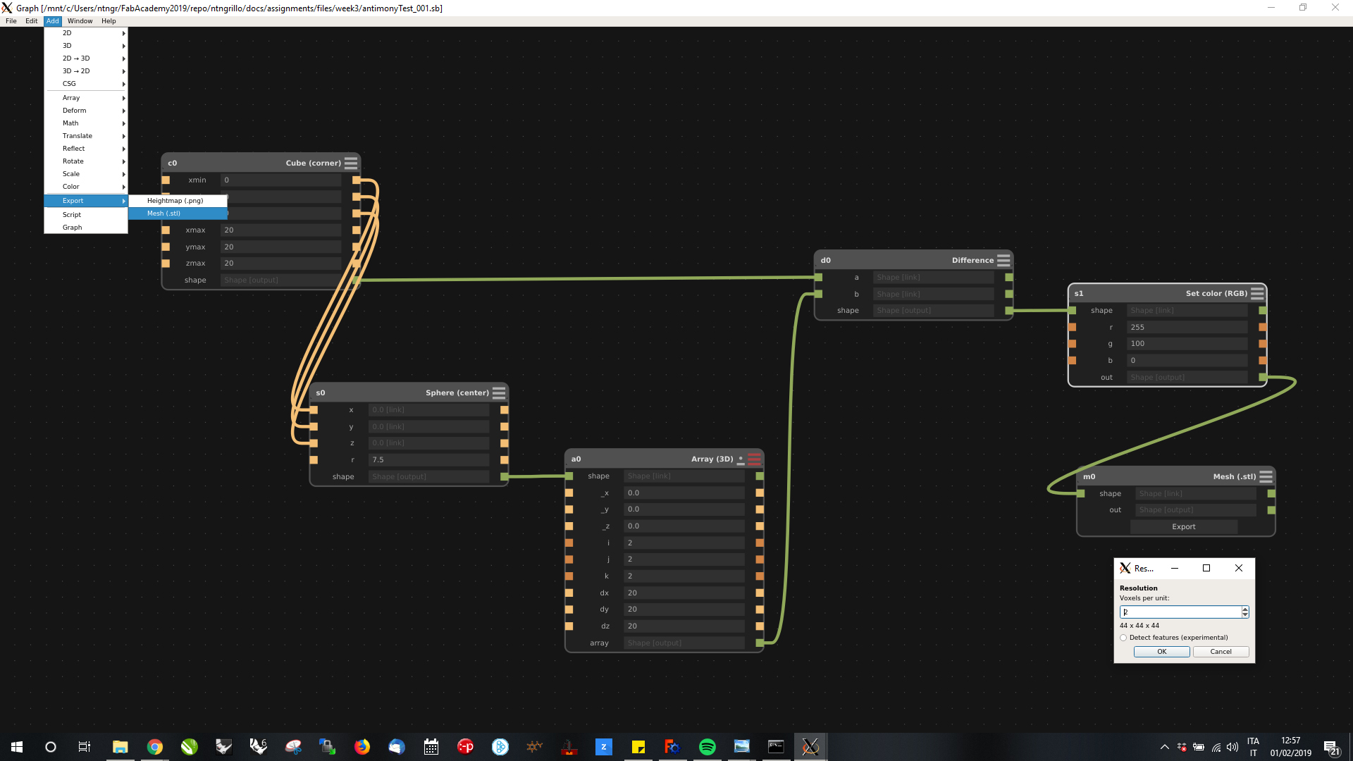
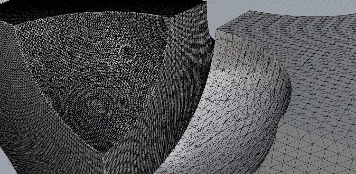
First I tried with a 44x44x44 and then with a 220x220x220, greatly improving the quality of the mesh but proportionally increasing the weight.
The experimental feature detection in more recent builds lets you preserve sharp corners and edges while using a much lower voxel resolution.
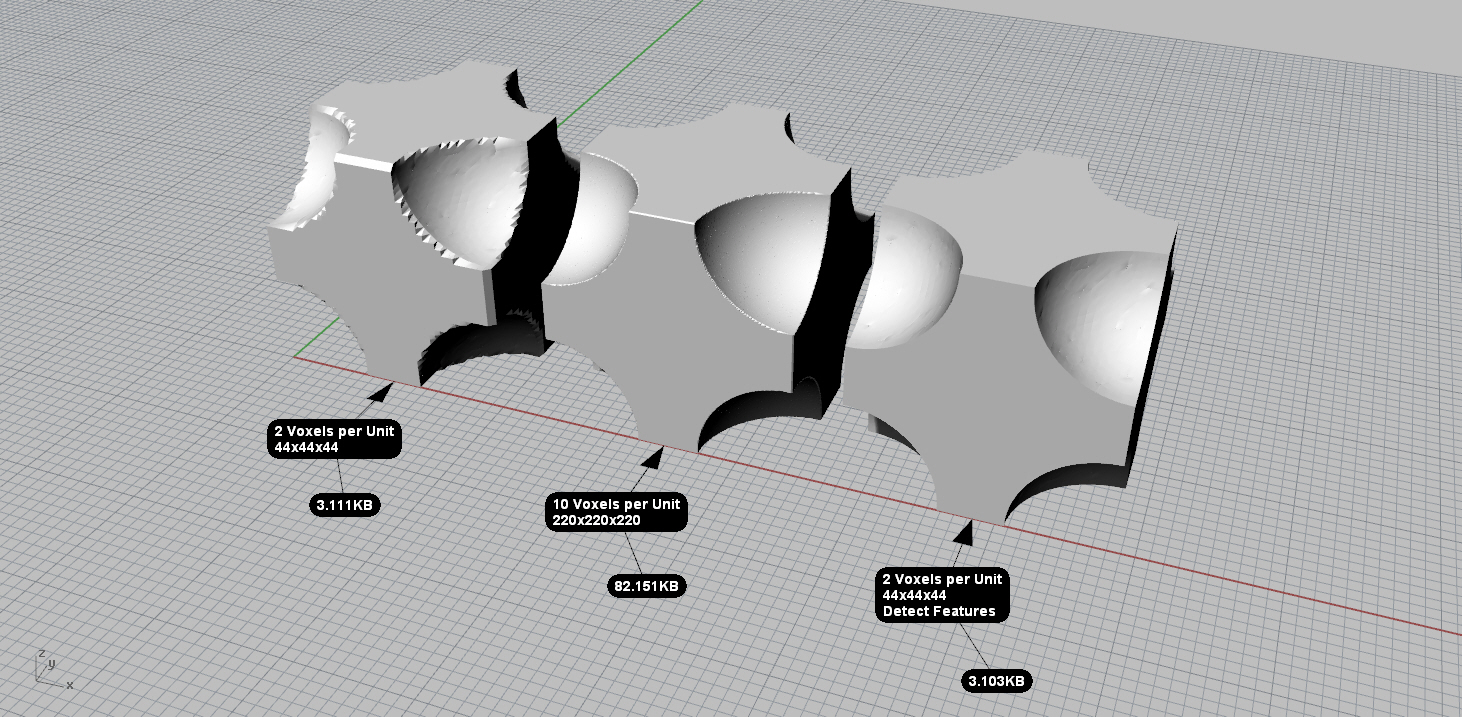
| Voxels per Unit | Matrix | Detect Features | weight (KB) |
|---|---|---|---|
| 2 | 44 x 44 x 44 | NO | 3.111 |
| 10 | 220 x 220 x 220 | NO | 82.151 |
| 2 | 44 x 44 x 44 | YES | 3.103 |
3D Object Representations
-
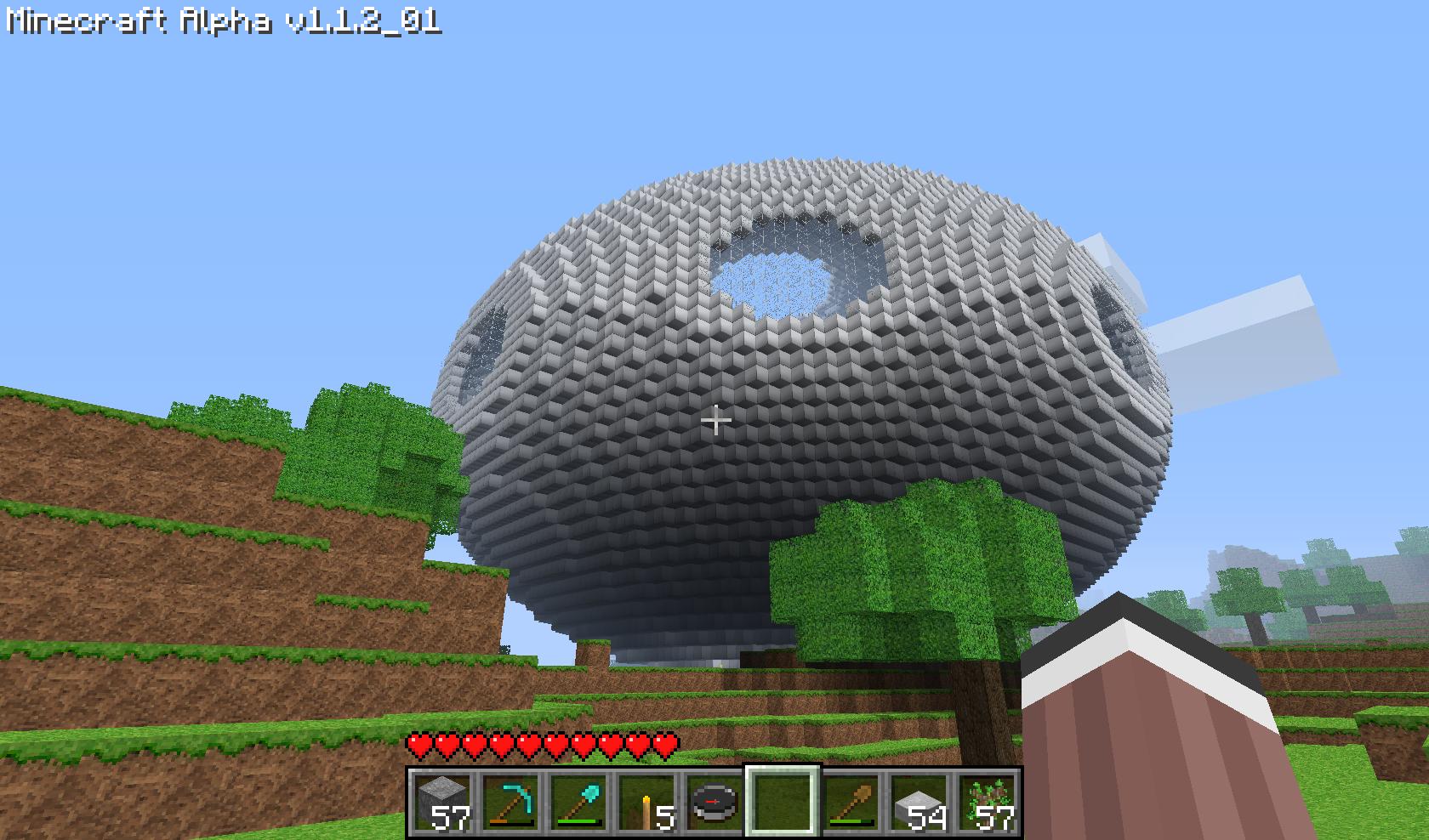
Voxel: it’s a Vo-lumetric pi-xel and represents a value on a regular grid in three dimensional space. This is analogous to the pixel for 2D bitmap image. As with pixels in a bitmap, voxels themselves do not typically have their position (their coordinates) explicitly encoded along with their values. Instead, the position of a voxel is inferred based upon its position relative to other voxels (i.e., its position in the data structure that makes up a single volumetric image). To produce a voxel representation the 3D space, this is splitted into equal intervals along the main orthogonal coordinate axes to obtain nx x ny x nz voxels (small cubes). If you want a clear example of how interesting can be a voxel world representation, play Minecraft
-
Octree
-
B-rep
-
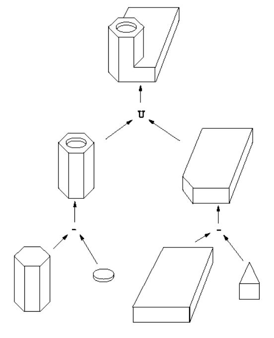
CSG: Constructive Solid Geometry is the easiest way to work with 3D solid geometry, with which you create complex objects by adding and removing pieces to or from solids using Boolean Operations, such as union, difference or intersection.
-
F-rep (Implicit representation): The functional representation defines a geometric object as a whole with the help of one real continuous describing function of several variables in the form
F(X) => 0. The traditional use of implicit functions in computer graphics includes: skeletons, generating scalar fields, or so-called “blob objects”; primitives of the structural geometry of solids (CSG); algebraic compartments of surfaces in the boundary representation.
Observations
The B-rep and CSG modeling schemes, albeit robust from the mathematical point of view, they have rather obvious limitations, such as:
-
difficulty of use: modeling operations are not very intuitive. Long training time is required to reach adequate levels of operation.
-
difficulty in representing, within the model, the intent of the designer: not geometrical constraints (parallelism, orthogonality, concentricity) can be codified, expressly.
-
difficulty in the management of the dimensions (parameters): the modification of a dimension is complex, and generally requires recalculation of the model.
Voxel vs Mesh
In contrast to pixels and voxels, points and polygons are often explicitly represented by the coordinates of their vertices. A direct consequence of this difference is that polygons are able to efficiently represent simple 3D structures with lots of empty or homogeneously filled space, while voxels are good at representing regularly sampled spaces that are non-homogeneously filled.
Outside of the games industry, voxels are commonly used for representing the output data of a CAT Scan, MRI, or Ultrasound. Since volumetric images are in three dimensions they are exponentially larger than 2D images and can be compressed using similar techniques.
Note
- A polygon cube mesh exported from Maya is 192500 bits or 19kB.
- A 512x512 image with 32 bits per pixel is 8388608 bits or 1.049 MB.
- A 512x512x512 image with 32 bits per pixel is 4294967296 bits or 536.9 MB.
Simply put, voxels contain lots more data than polygons and that adds up to a lot of memory.