6. 3D Scanning and printing
3D Printing
Group Work
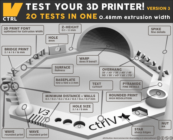
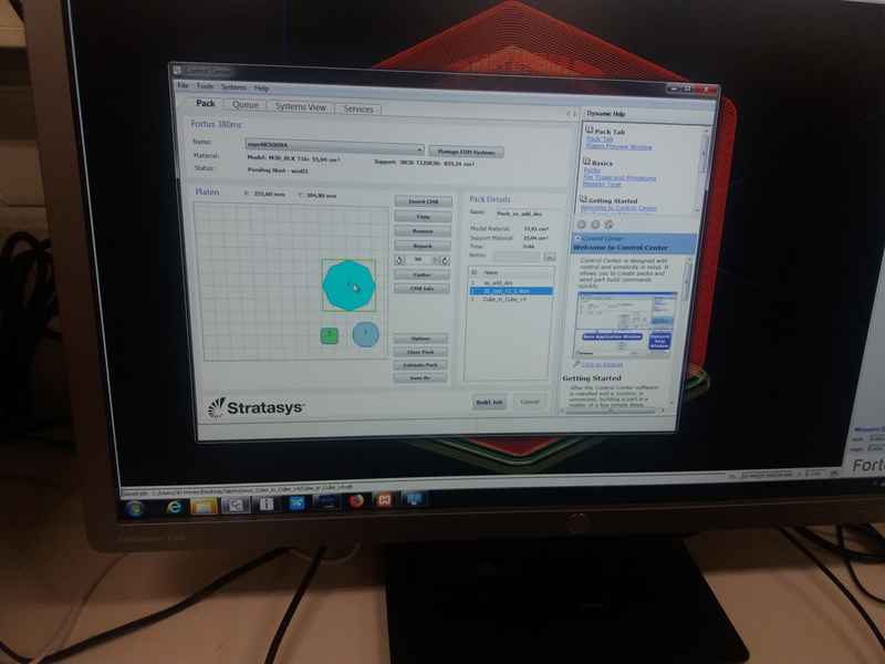
For the group task, I worked with Arash and Michael to test 3 printers: 1) Stratasys Fortus 380mc 3D that uses ABS (Acrylonitrile butadiene styrene), 2) Sindoh 3D Vox that uses PLA (Polylactic acid), and 3) FormLabs Form2 that uses resin. The first two printers are based on Fused Filament Fabrication technology and the Formlabs is based on stereolithography (SLA). We used the same test piece as other groups and in order to save time, we sent multiple jobs to the printer: The test piece and our individual designs. When sending the designs for printing, it is possible to specify different settings for each design. We used Test your 3D printer file as the test design.
|
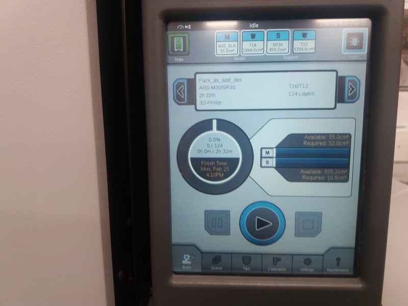
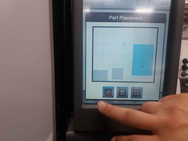
Stratasys Fortus 380mc 3D
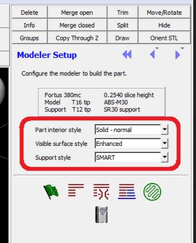
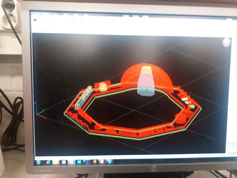
First, I opened the STL file in the Insight program and the important settings from the main window are Part interior style (sparse), Visible surface style (enhanced), Support style (smart). Then I pressed Finish and Built the job
|
|
|
|
|
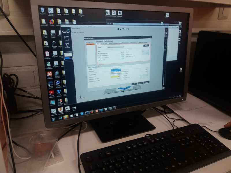
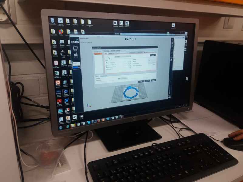
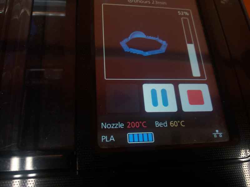
Sindoh 3D Vox
Sindoh 3D Vox
|
|
|
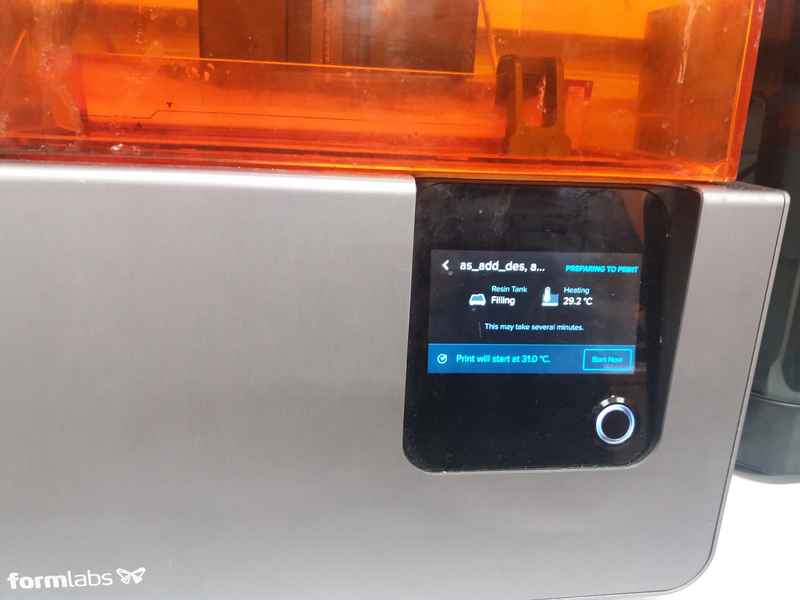
FormLabs Form2
We tried out the Formlabs Form2 printer in our FabLab. It prints the model into resin, the finished model is cleaned in using Isopropyl alcohol and then cured in 405 nm light. As it uses Class 1 laser and toxic resin, precautions should be taken to use it safely. The safety guidelines are available here
|
|
|
|
| Test | Fortus 380mc 3D | Form2 | 3D Vox |
| Nut, Size M4 Nut fit | Pass | Pass | Pass |
| Wave, Rounded Print | Pass | Pass | Pass |
| Star, Sharp Edges | Pass | Pass | Pass |
| Text Cutout, Complex Shapes | Legible | Best | Good |
| Holes, Size 3, 4, 5 mm | Pass | Pass | Pass |
| Minimal Distance: 0.1, 0.2, 0.3, 0.4, 0.5, 0.6, 0.7 mm | 0.5 | 0.2 | 0.4 |
| Z height: 0.1, 0.2, 0.3, 0.4, 0.5, 0.6, 0.7, 0.8, 0.9, 1.0, 1.1 mm | Pass | Pass | Pass |
| Bridge Print: 2, 4, 8, 16 mm | Pass | Not clear | Pass |
| Sphere, Rounded Print 4.8mm height | Pass | Pass | Pass |
| Sphere Mix, 7 mm height | Pass | Pass | Pass |
| Pyramid, 7 mm height | Pass | Pass | Pass |
| Overhang: 25, 30, 35, 40, 45, 50, 55, 60, 65, 70° | Pass | Pass | Pass |
| Warp, does it bend? | No | No | No |
Individual Design
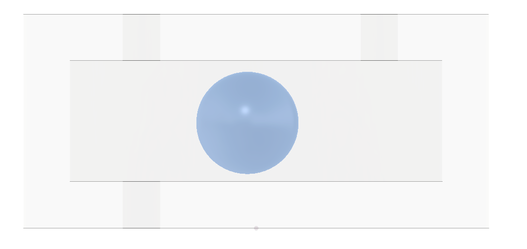
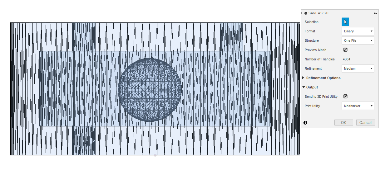
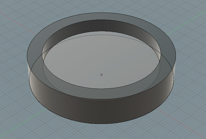
Design
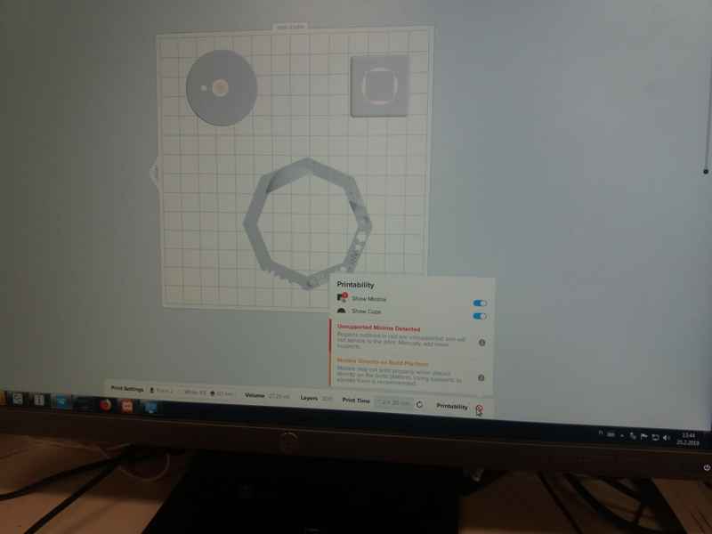
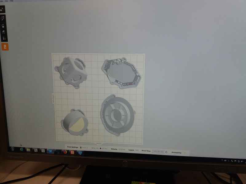
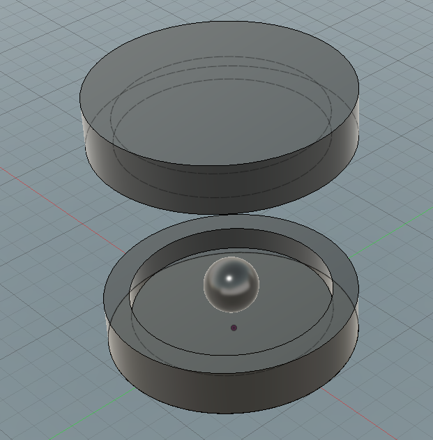
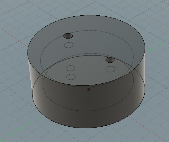
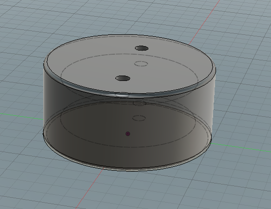
I designed a sphere inside a circular cavity. The design file can be downloaded from here. As the design includes a floating object inside a closed surface, it is not possible to make it subtractively.
|
|
|
|
|
|
Results
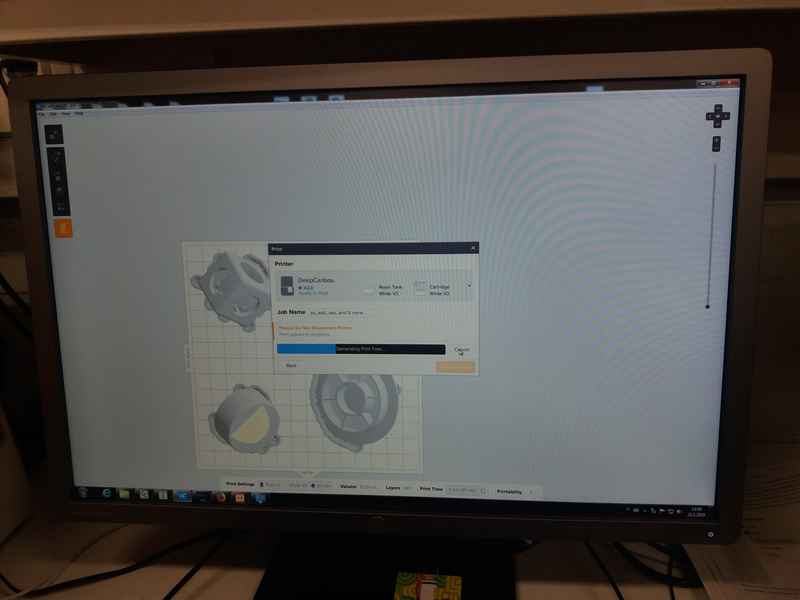
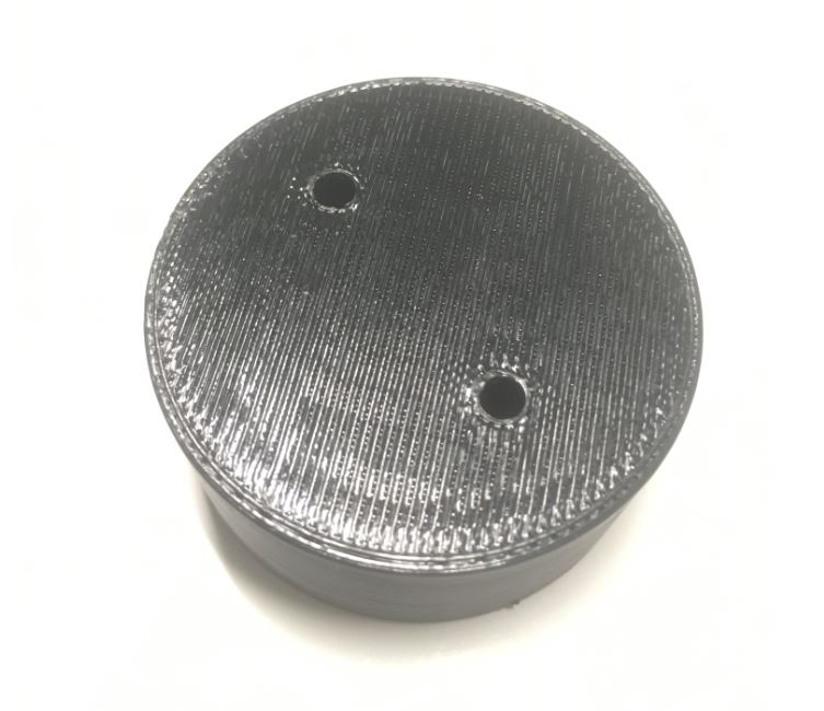
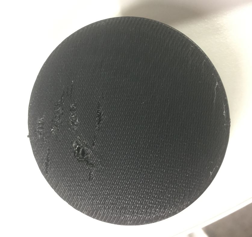
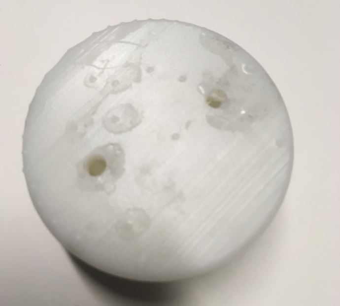
I sent the stl file for printing on both Fortus 380mc 3D that uses ABS and FormLabs which uses resin for printing. The job at Fortus took roughly two hours and at Formlabs took about five hours. The part printed at Fortus was then dropped in a tank of NaOH to remove the support material. The part printed at Formlabs was cleaned in a tank of Isopropyl Alcohol and then was cured under 405 nm light. I soon realized that the holes I created were not large enough to remove the support material from the ball, so I had to drill some holes to knock the inner sphere free. Same was the story with the Fortus print after 8 hours of soaking in the NaOH solution. Thus, I left it again in the solution to soak for a longer duration. After another overnight soak, all the support material dissolved thus freeing the inner sphere.
|
|
|
Afterthoughts
I made a closed cylinder which enclosed a floating sphere, which when agitated makes a rattling sound i.e., a kind of rattle. The design incorporates a hollow cavity with a very small opening in the outer object. The hole size on the outer cylinder is small so the inner sphere cannot be placed inside after the cylinder is finished. Furthermore, if using a milling process, the milling bit will not be able to reach all the corners to actually carve a sphere inside. Provided these facts, this design could only be manufactured via 3D printing.
The biggest advantage of 3D printing is that one can make complex prototypes quickly and easily. As a downside, depending on the process and material used, it can be quite costly, and machines themselves are not cheap either. There have been some notable examples where 3D printing has been used for mass production too. Deciding when to use 3D printing over traditional methods is a complex equation with too many parameters and should be looked at case by case basis.
Two different type of techniques were used in this assignment, namely SLA and FDM. Following are the Pros of SLA technique over FDM
- Higher resolution and precision.
- Gives a much better finish.
Following are the Pros of FDM technique over SLA
- Generally cheaper
- No postprocessing required
3D Scanning
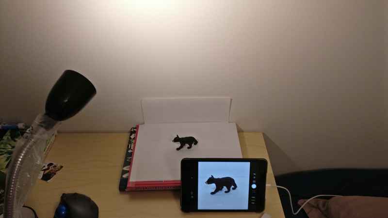
To do the 3D scanning, I used Photogrammetry. According to Wikipedia
Photogrammetry is the art and science of making measurements from photographs, especially for recovering the exact positions of surface points.
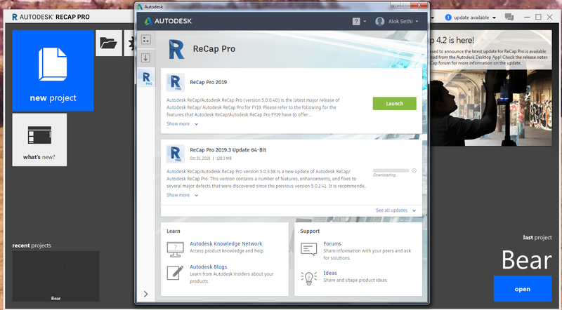
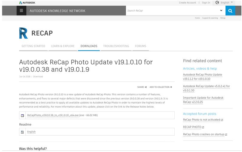
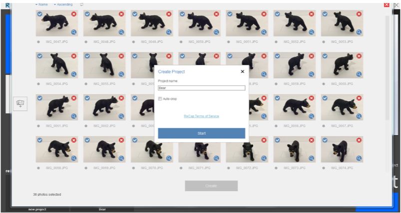
I used AutoDesk Recap and followed Jari’s tutorial. First, I installed the AutoDesk Recap Pro (and Recap Photo) 2019 from here. After downloading and installing, I registered as a student and received a 2years free license. When I launched the software for the first time, I had to get all its update from the top right corner. This updated the ReCap Pro not ReCap Photo. Then I clicked on new project and selected the Photos to 3D option. Here again, I had to download and install an update for ReCap Photo from this page.
|
|
After ReCap Photos update, I launched ReCap Pro again and selected the Photo to 3D option. This time, ReCap Photo was launched. I selected to create a 3D model using an object. I then selected option to open image files and select the folder where my pictures were saved. Next, the software started to process the images. It took a couple of minutes.
|
|
|
|
|
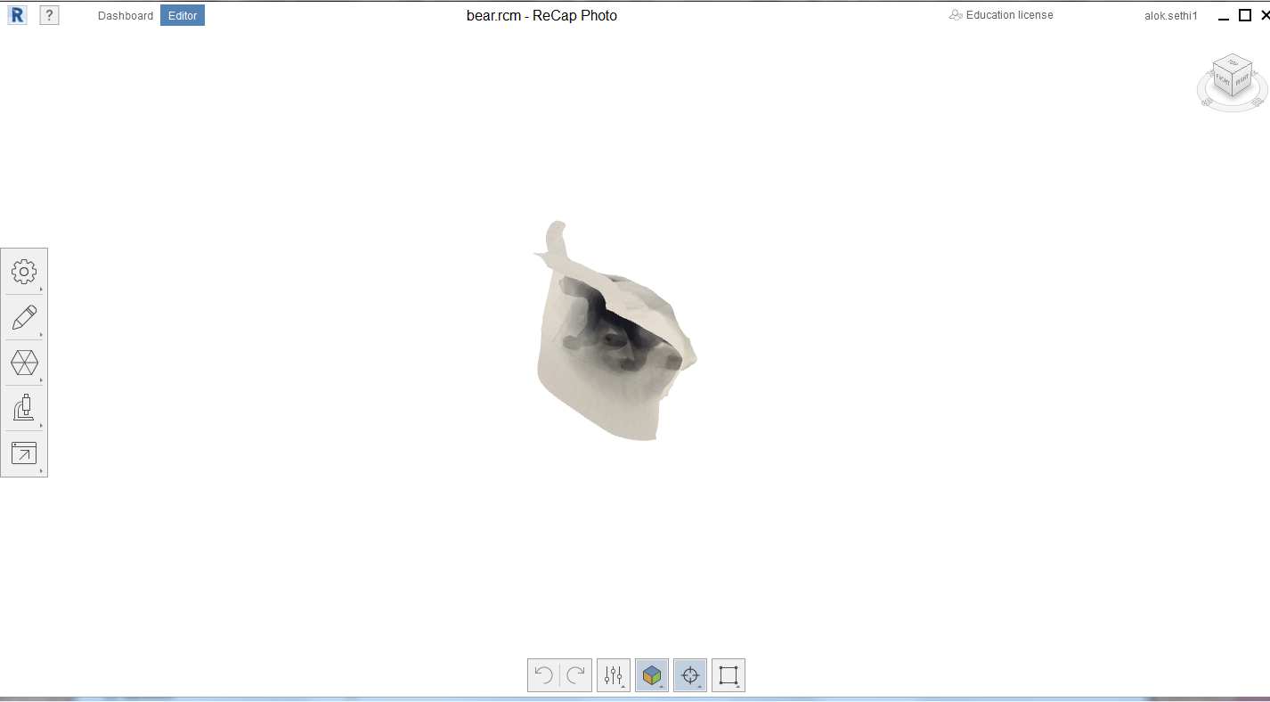
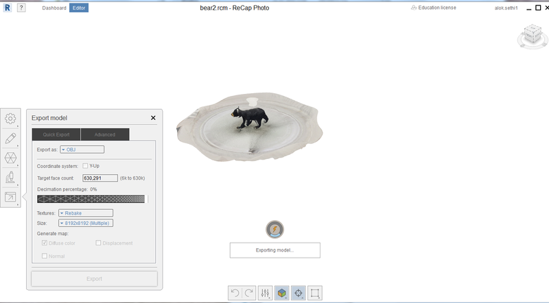
The first attempt wasn’t good. The model rotated, the paper backing became an organic shape and merged with the desired object. Furthermore, I only got the front side of the bear. Also, the second leg of the bear went missing. The second attempt yielded much better results.
|
|
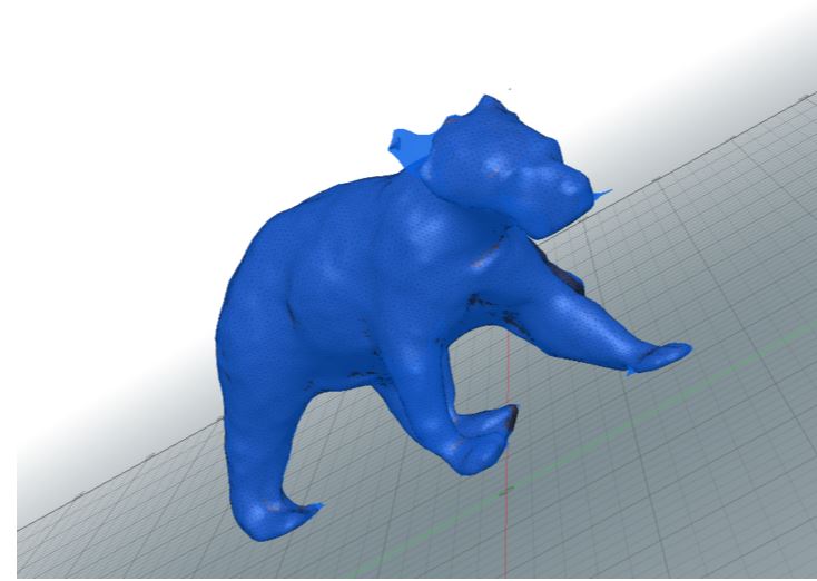
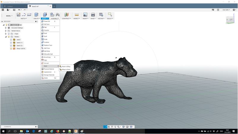
Even though the second attempt yielded much better results, the results were still not very good. First, the file size was big which crashed Fusion 360 once. After deleting the mesh points related to the bottom tray, the number of mesh points become manageable. However, nice details on the bear face were missing and so was one of its ear. Furthermore, one of the front paw seems to be merged with the bottom plate.
Unfortunately, the model file is too bit to be uploaded here..
Update: Didn’t manage to reduce the file size by re-meshing. However, I saved the data as text STL file and then zipped it. The attached file below is a zipped version.
|
|
Afterthoughts
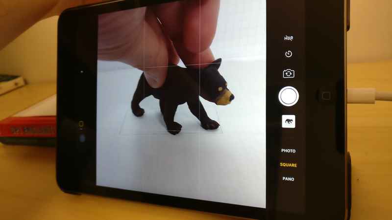
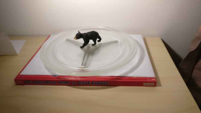
Although it is nicer to get a quick replica of some existing object, the process however is painful. To get a good model you need good lighting, good camera, an object which scans nicely and a powerful machine to edit the generated model.