12. Output devices
Board Design
I wanted to finish the board design which I started last week. By the end of last week I had managed to design a second version of the PCB. This week I manufactured the PCB and stuffed it.
|
|
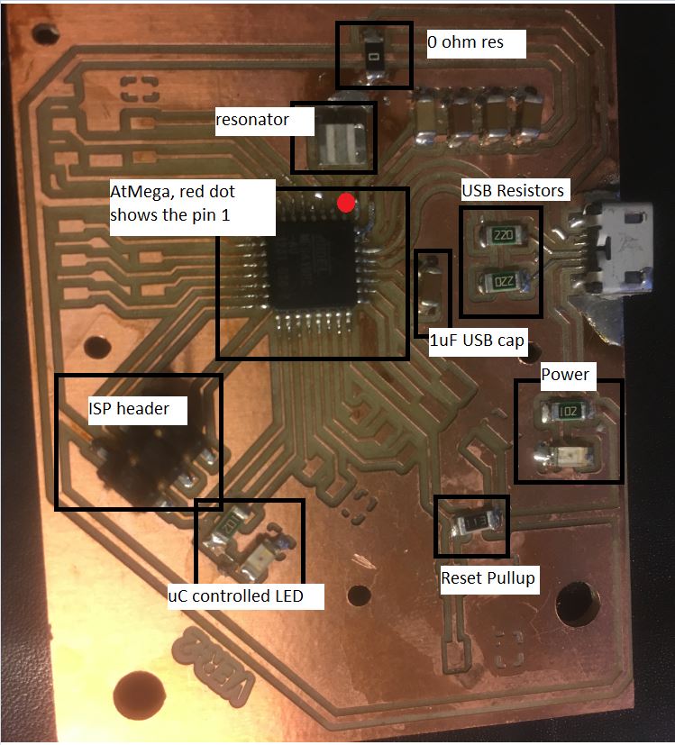
Following components are currently on the board
|
|
I still haven’t completely stuffed the board, only the most essential ones. While making the board work I learned one important thing and that was to make sure that the reset pull-up resistor is connected before trying to program the board. I tried to program it without putting the pull-up resistor and avrdude was not even able to recognize that any micron-controller was plugged in.
The line for custom programming tool for this board is
avrdude.exe -p m16u2 -c usbasp -P usb -e -Uflash:w:"$(OutputDirectory)\$(OutputFileName).hex":i -CC:\Users\asethi\Desktop\fablab\fabacademy\avrdude-6.3-mingw32\avrdude.conf
I have tested this board with the most basic program as of now. In future I will use this board for any further exercises.
#include <avr/io.h>
#include <util/delay.h>


int main(void)
{
    unsigned int delay = 10;
    unsigned char count=0, i;
    DDRB |= (1<<PB4);
    /* Replace with your application code */
    while (1)
    {
        count ++;

        if (count > 10)
        {
            count = 2;
        }


        for (i=0;i<count;i++)
        _delay_ms(delay);

        PORTB &= ~(1<<PB4);

        for (i=0;i<count;i++)
        _delay_ms(delay);


        PORTB |= (1<<PB4);

    }
}
avrdude.exe -p m16u2 -c usbasp -P usb -e -Uflash:w:"$(OutputDirectory)\$(OutputFileName).hex":i -CC:\Users\asethi\Desktop\fablab\fabacademy\avrdude-6.3-mingw32\avrdude.conf
Board Problems
-
Unfortunately after connecting the USB resistors , the board is not getting powered up by the USB. The power LED blinks three times and then turns off. This might be a symptom of host USB trying to determine the current requirement and then turning off the power after seeing that the board requires more power. I haven’t found a solution for it as of now.
-
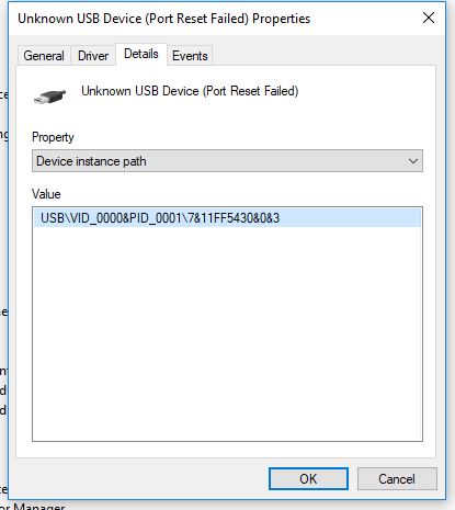
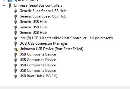
After connecting the debugger the board does stays powered up but does not get recognized as a valid USB device
|
|
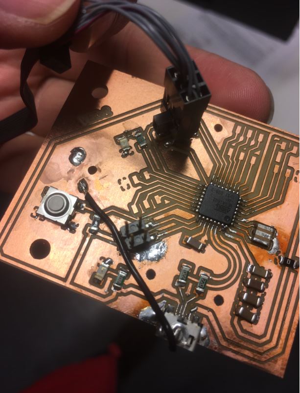
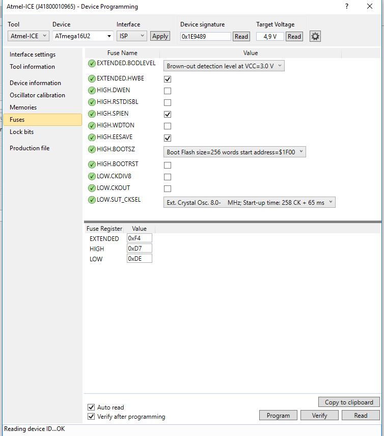
UPDATE: Have managed to fix all the problems now with the board. Following changes were done
- Removed the resonator and changed it to an 8MHz value. I was not able to verify that the resonator I had put earlier was in fact 16MHz.
- Added a jumper wire from the body of the USB connector to the negative power plane of the board.
- Corrected the fuses
- Correct values of preproceesor defines in the code (F_CPU and F_USB). Both were set to 8000000
|
|
Output Devices
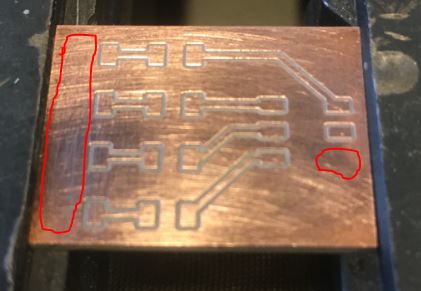
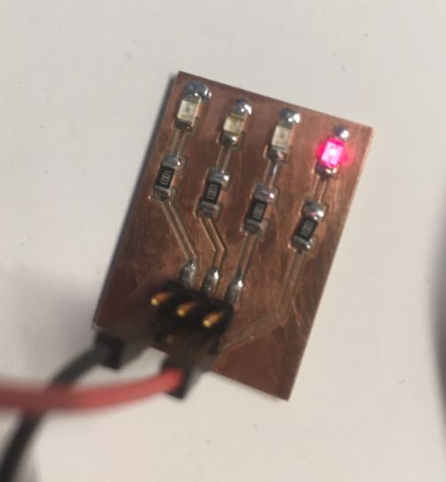
I tested various LEDs as an output device this week. Below you can see the manufactured PCB, notice the red circles where ground pads were supposed to be. The problem seems to be in the tool path file. It happened because I defined the endmill as 0.4mm and the space was not enough to fit the endmill and so mods didn’t generate any toolpath for it. Irrespective of that, I was able to solder the components.
|
|
As now my USB board is working, I made use of LUFA to make the board behave as a serial and HID device. I modified the CDC_MOUSE example to create a virtual serial and a Joystick device. As a serial device, I can send commands via serial and the microcontroller toggles the on board LED based on that. The LED is turned on by writing ‘1’ and turned off by writing ‘2’ on the serial.
Following is the code changes
void handle_rcvd_serial_byte(int16_t data)
{

    char       ReportString[10];//  = "Echo:";
    //char * ptr;

    //ReportString[4] = (char)(((uint16_t)data & 0xf0)>>8);
    //ReportString[5] = (char)((uint16_t)data & 0x0f);
    //ReportString[6] = '\0';
    sprintf(ReportString, "echo:%c",data);

    if (data == '1')
        PORTB |= (1<<PB4);   // turn on  a LED by writing 1 on serial
    else if (data == '2')
        PORTB &= ~(1<<PB4);     // turn off  the LED by writing 2 on the serial

    CDC_Device_SendString(&VirtualSerial_CDC_Interface, ReportString);

}
/** Main program entry point. This routine contains the overall program flow, including initial
 *  setup of all components and the main program loop.
 */
int main(void)
{
    SetupHardware();

    LEDs_SetAllLEDs(LEDMASK_USB_NOTREADY);
    GlobalInterruptEnable();

    for (;;)
    {
        uint16_t num_bytes;
        int16_t data;

        CheckJoystickMovement();
        num_bytes = CDC_Device_BytesReceived(&VirtualSerial_CDC_Interface);
        /* Must throw away unused bytes from the host, or it will lock up while waiting for the device */
        data = CDC_Device_ReceiveByte(&VirtualSerial_CDC_Interface);
        if(num_bytes > 0)
        {
            handle_rcvd_serial_byte(data);
        }
        CDC_Device_USBTask(&VirtualSerial_CDC_Interface);
        HID_Device_USBTask(&Mouse_HID_Interface);
        USB_USBTask();
    }
}
Group Work
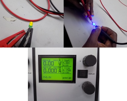
For this task, we (I, Michael, Jobin, Sahan, and Yasir) measured the power consumption of a 5 mm LED and an RGB LED. The power consumption of the LEDs was measured by directly powering them with a variable power supply and varying the applied voltage and current limit in order to measure the resulting effect on the brightness of the LEDs.
|
In both tests, we burnt the LEDs by exceeding their voltage and current limits. For the 5 mm LED this was 6.5 V and 188 mA (it is probably lower than these values). Blue and Green LEDs can be fed with a maximum current of 100 mA (Peak Forward Current) for a very short time without being damaged. The peak forward current is the absolute maximum current that an LED can handle and this is only for a short period of time. The peak forward current, specified on a data sheet, can only be applied to an LED for the time period specified. This time period is either specified as a fraction of a duty cycle or as a time in milliseconds 3.
Measurement values for 5 mm Green LED

|
For the RGB, we repeated the same process as with the 5 mm LED, testing the effect of varying the voltage and current on the brightness. If current is increased the LEDs brighten and if decreased, the LEDs become dimmer. According to the data sheet, this LED has Forward Voltage ranging from 2 - 4 V. 2 - 2.6 V for Red, 3.2 - 4 V for Green, and 3.2 - 4 V for Blue. The absolute maximum ratings for the Forward Current (the current flowing across the LED from positive to negative in order for the LED to get power) for Red is 50 mA and for Green and Blue it is 25 mA (milliamps) when powered individually as we did. We tested the power consumption from a low of 1.60 V and 0.001 Amps, which didn’t power on the LED, to a high of 6.5 V and .200 A. Red was very dim at 1.9V and 0.001 Amps and the optimal value was 2.3 V and 20 mA. With the recommended electrical characteristics of 20 mA, Red has an average forward voltage of 2.0 V, Green 3.2 V, and Blue 3.2 V, respectively.
Files
- Atmel Solution
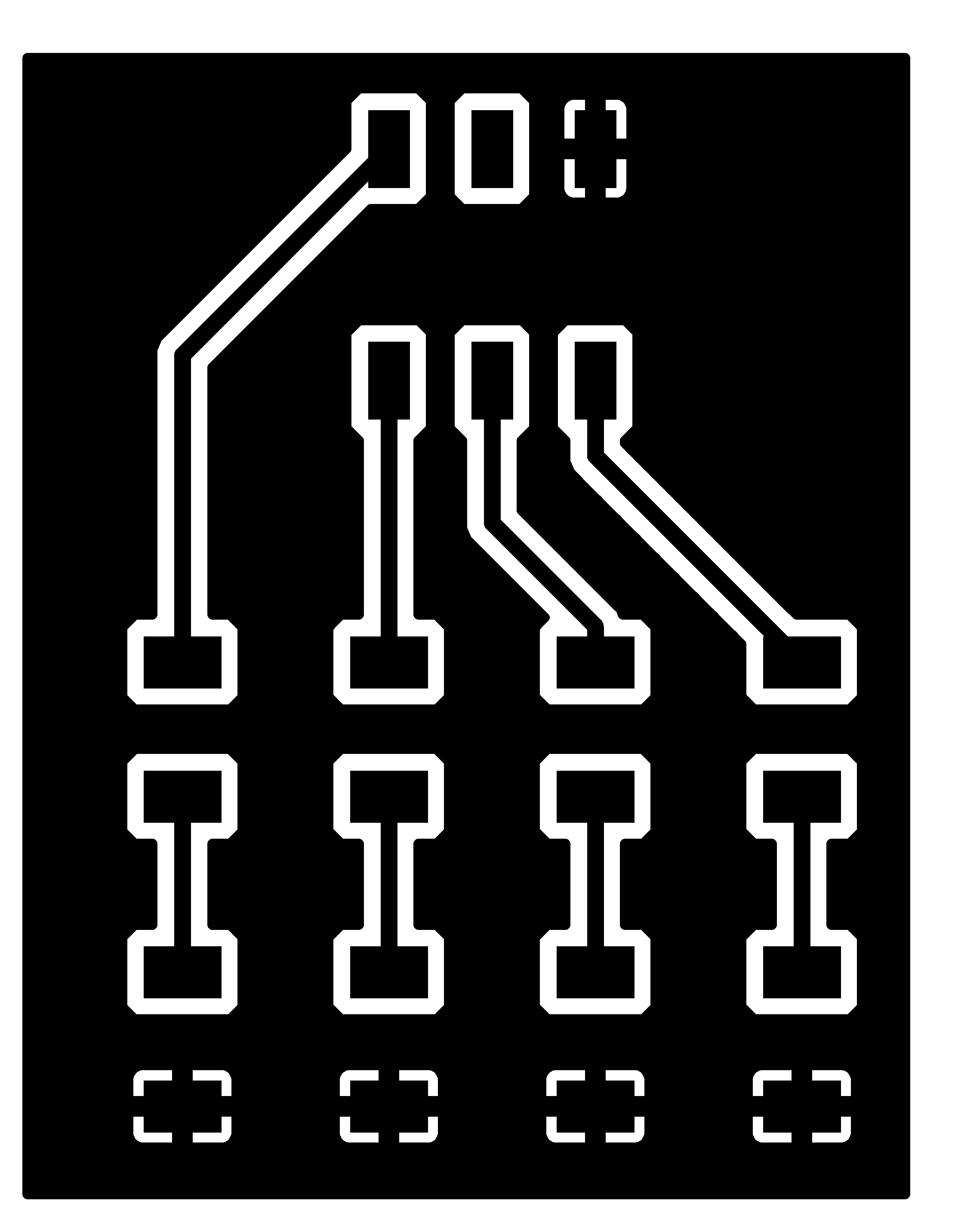
- LED breakout (schematic) / (board)
- LED breakout traces](png) / (rml)
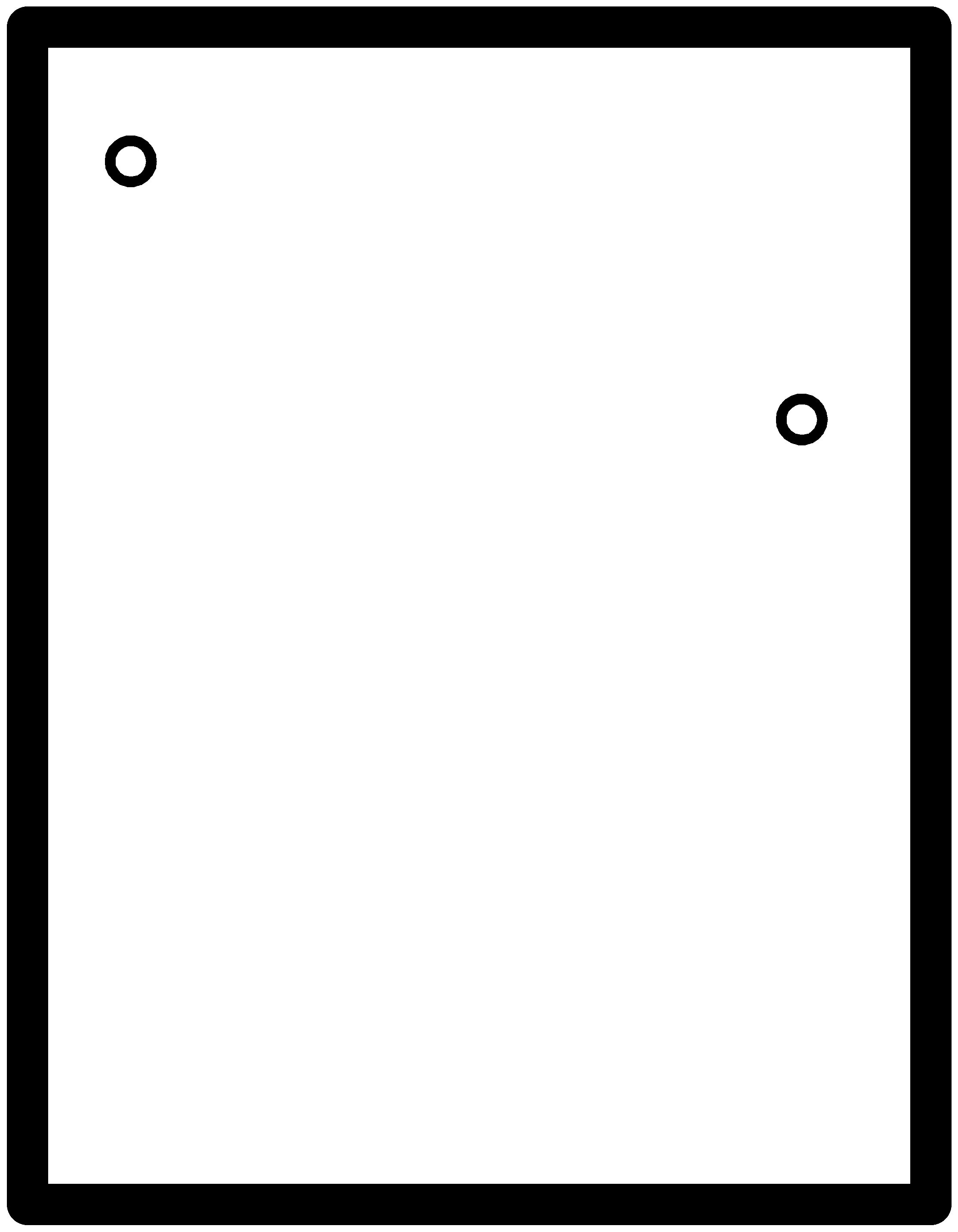
- LED breakout outline(png) / (rml)
- Hex File