Final Project
First Idea
Automated mmWave DUT OTA test setup
Requirements
As I work in the wireless development field, one challenge I face is to do the measurements in the outdoors. The setup roughly consists of an antenna panel with amplifiers and other equipment mounted on a movable stand. Depending on the goals of the measurement campaign, the antenna panel is rotated and moved manually in different directions and measurements are recorded. As expected, this is rather cumbersome task and this is the challenge I want to automate and tackle during my final project.
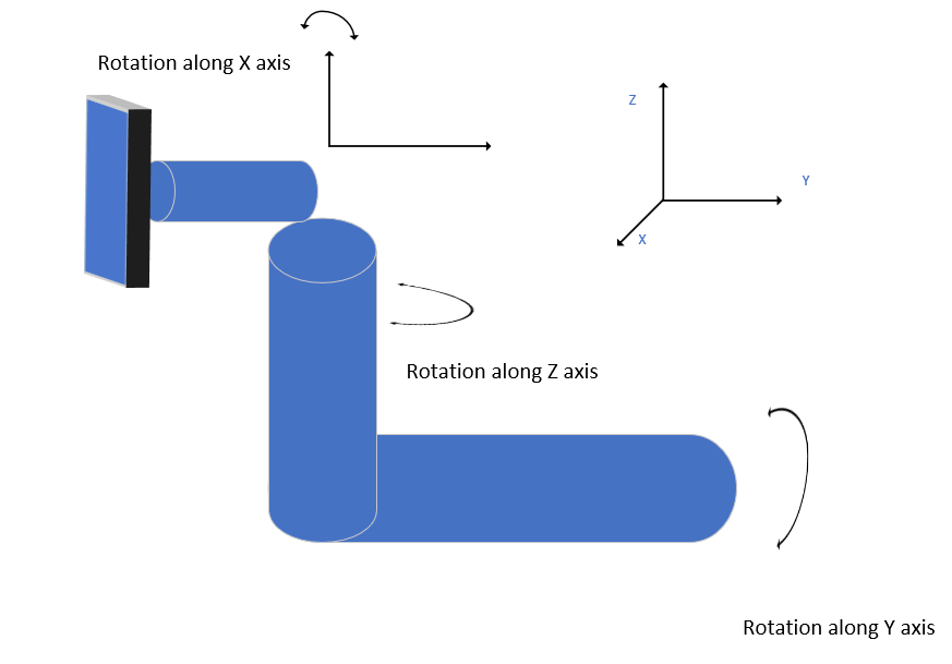
I want to make a mount for a cuboid which weighs roughly about 5 Kg and have dimensions of 30 by 40 cm and a depth of about 20 cm. The mount should have 6 degrees of freedom. First three degrees are related to linear movement along X,Y and Z axis and the other three degrees are related to rotation along X, Y and Z axis. A rough sketch showing the three rotational axis is shown in the sketch below.
|
Finally, there will be multiple such nodes with one master and multiple slaves and controllable from one central location. With this multi node system, i will be able to automate the manual parts of the radio channel measurements.
Reflection
Given the complexity and the scale of the design, I think I will start with one rotational axis. I will be very happy if I manage to do all three rotational axis as part of the final project. Three linear axis design will be taken from other people. As I anyway not going to do any OTA measurements over the course of this year, the timelines for the finished product are more relaxed.
Research
Input Sensors
- Distance measurement (figured out during Input week that Fablab Oulu does not have HC-SR04 (ultrasonic sensor module) and I don’t have enough time to actually make a receiver and transmitter for the distance measurement using the ultrasonic transducers.
- Rotary encoder for exact position. Again have to make them.
Output/Control
- Matlab via serial or Ethernet (for the master node)
- WiFi to talk with other nodes
Second Idea
Wake up light
Requirements
A night stand lamp which can display time, has mood lighting, can change brightness of the main lamp as an alarm feature. The project has a healthy mix of mechanical and electronics design work, with mechanical being mostly enclosure and aesthetics.
Reflection
The idea is a straight ripoff from the commercial products but as the products I am trying to imitate are above 100 euros, I might still give it a try.
Input Sensors
- Touch/button
- Temperature
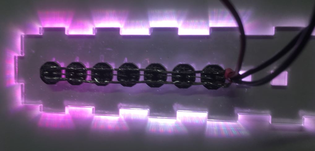
- RGB LEDs for mood lighting
- Bright White LED with controllable brightness
- RTC
Output/Control
- Connection to phone to sync time and settings. However, I don’t use an android phone and I don’t have a Macintosh computer to build an app for iPhone.
Third Idea
Tiny Keyboard and mouse that supports my laziness and also alleviates the wrist pain from constant mouse use.
Requirements
A small keypad with the ability to map multiple keystrokes/actions to individual keys
Final Project
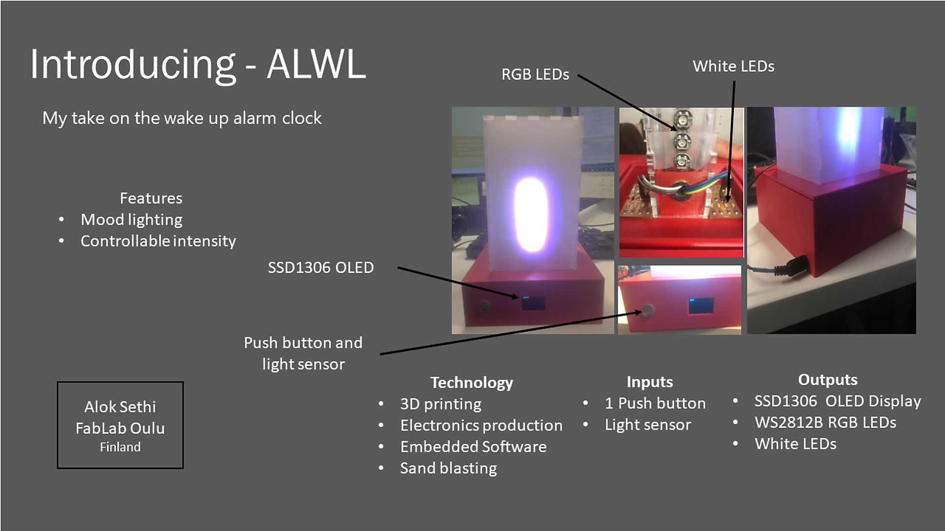
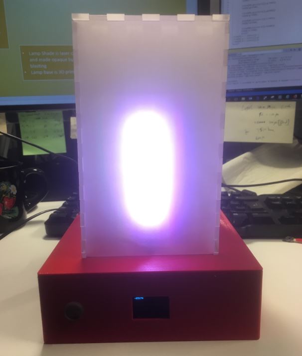
As mentioned in the Applications and implications week, I have build a wake up light. Check the Applications and implications page for more details regarding the questions related to the assessment guide. On this page I have documented the details of the tasks related to the final project.
Presentation
|
Features
Right now it performs the following function
- Mood lighting
- Bright white light which can be turned on and off
Design
2D Design
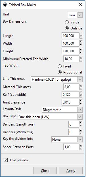
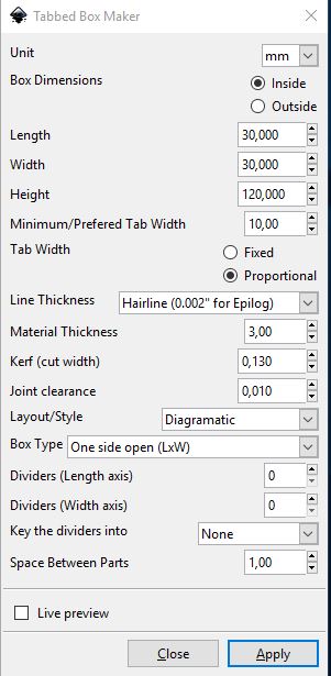
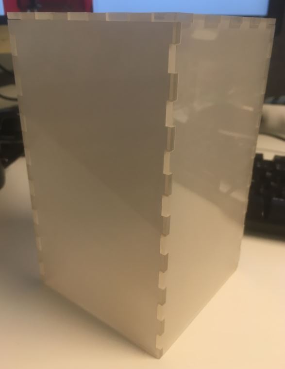
The shade for the lamp has been designed using Inkscape and cut using laser cutter. To give the shade a diffused look, it was sandblasted on one side. For creating the shade, tabbed box maker extension was used in Inkscape with the following settings.
|
|
|
|
3D Design
All the 3D objects were designed using Fusion 360.
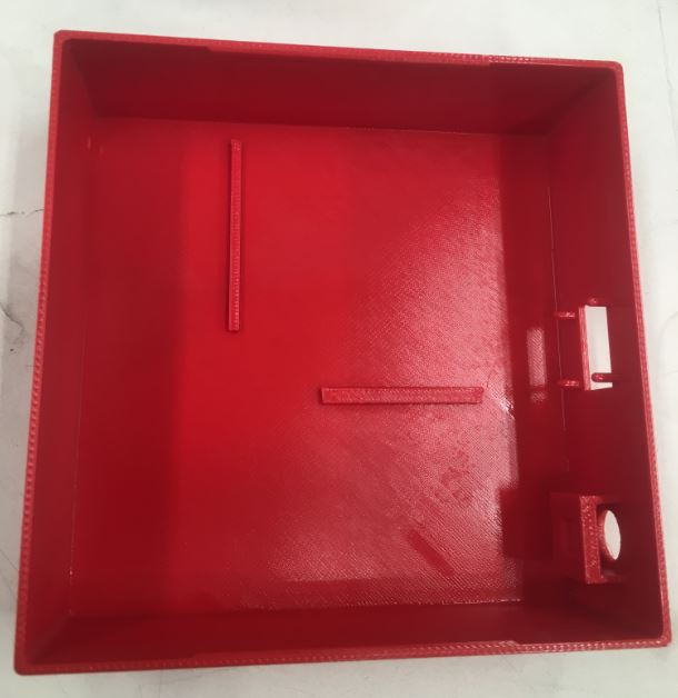
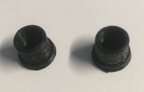
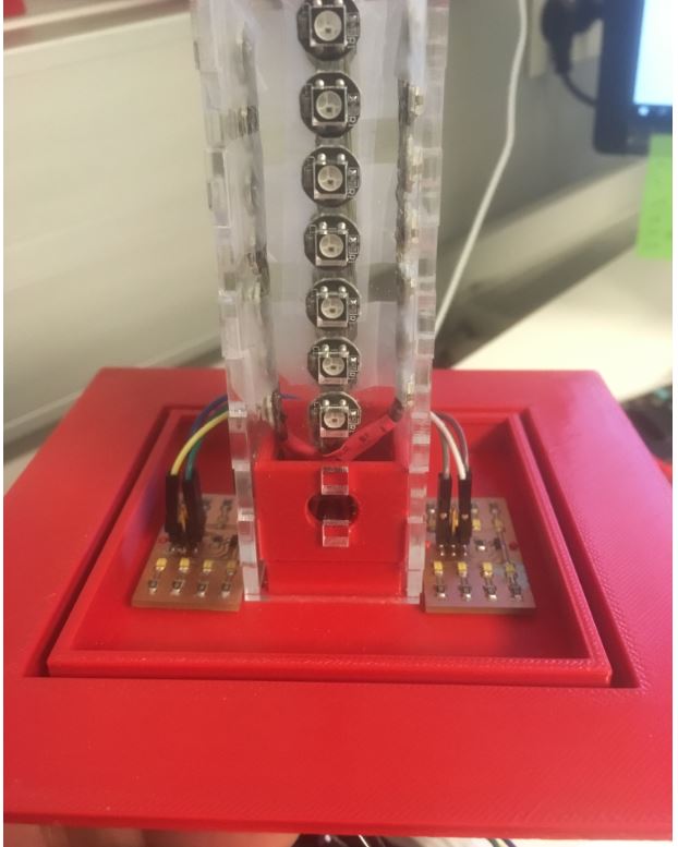
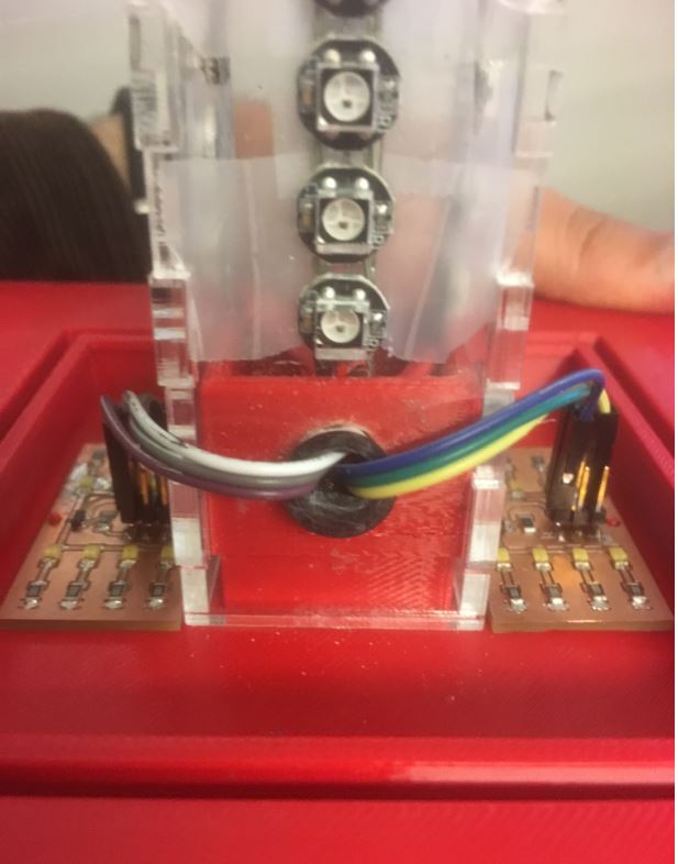
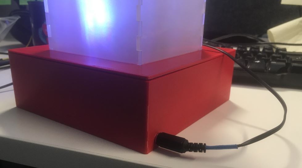
The base of the lamp consists of two separate pieces, a top half which holds the two acrylic shades and the bottom part, which houses the button, OLED and other electronics. It is printed in Red ABS plastic using Stratasys Fortus 380mc 3D.
|
|
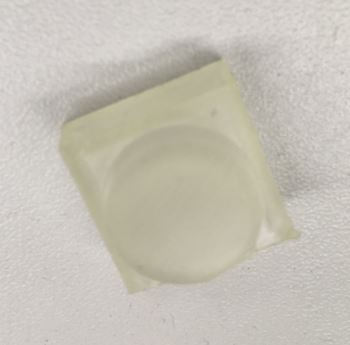
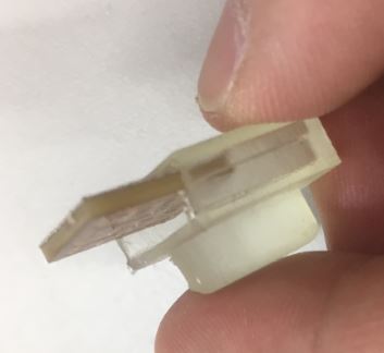
The button is made with clear resin using FormLabs Form2

|
|
|
Unfortunately, the designed button was too big to install in the available cavity I made in the base of the lamp. So, in order to fit the button, I sawed off the cavity for the button and welded a new bigger cavity using acetone.
|
|
|
Electronics Design
In the final project, I have used the following PCBs
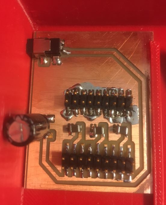
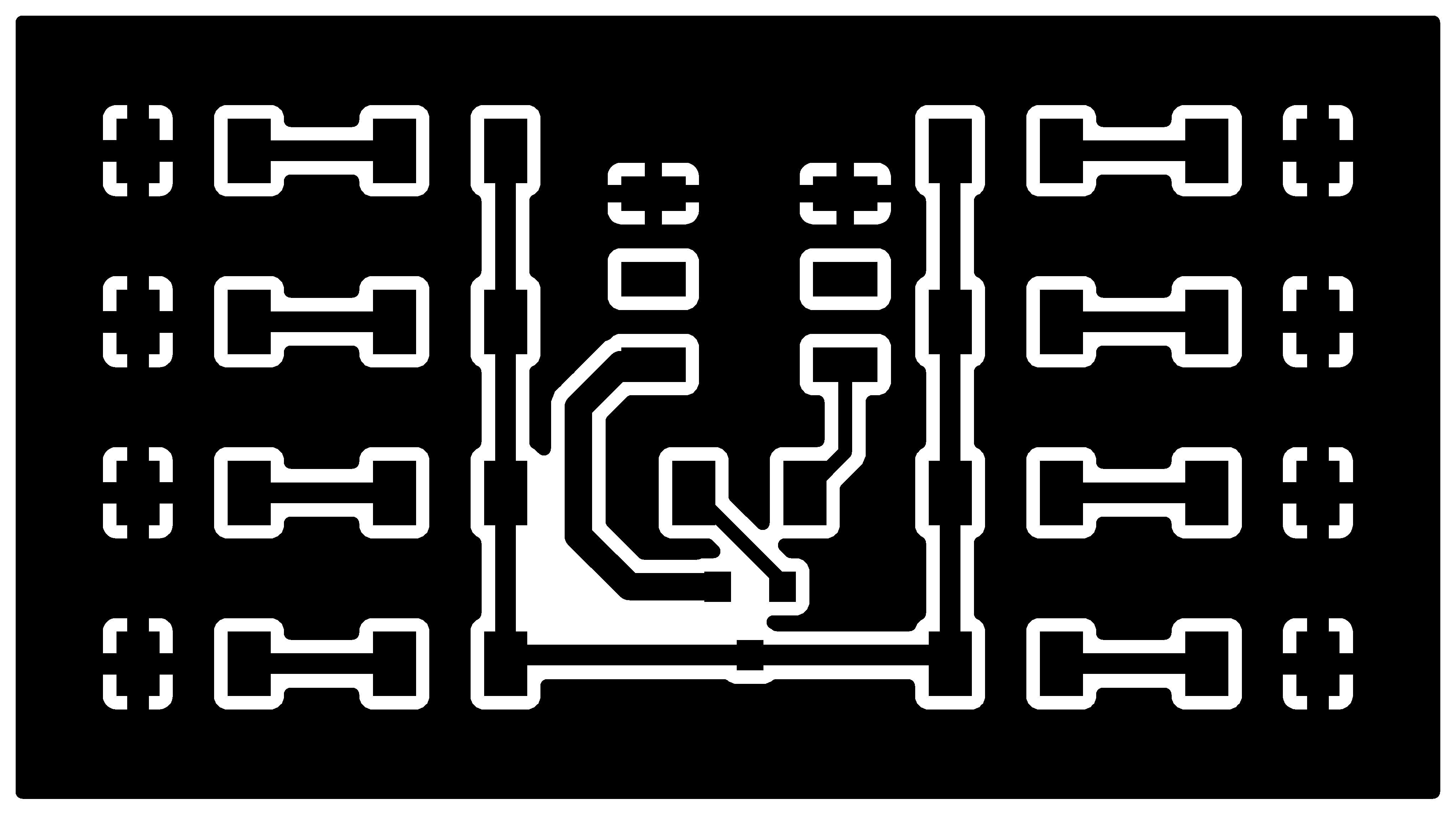
- Power Board This board provides power to different parts of the project.
|
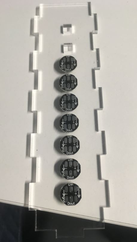
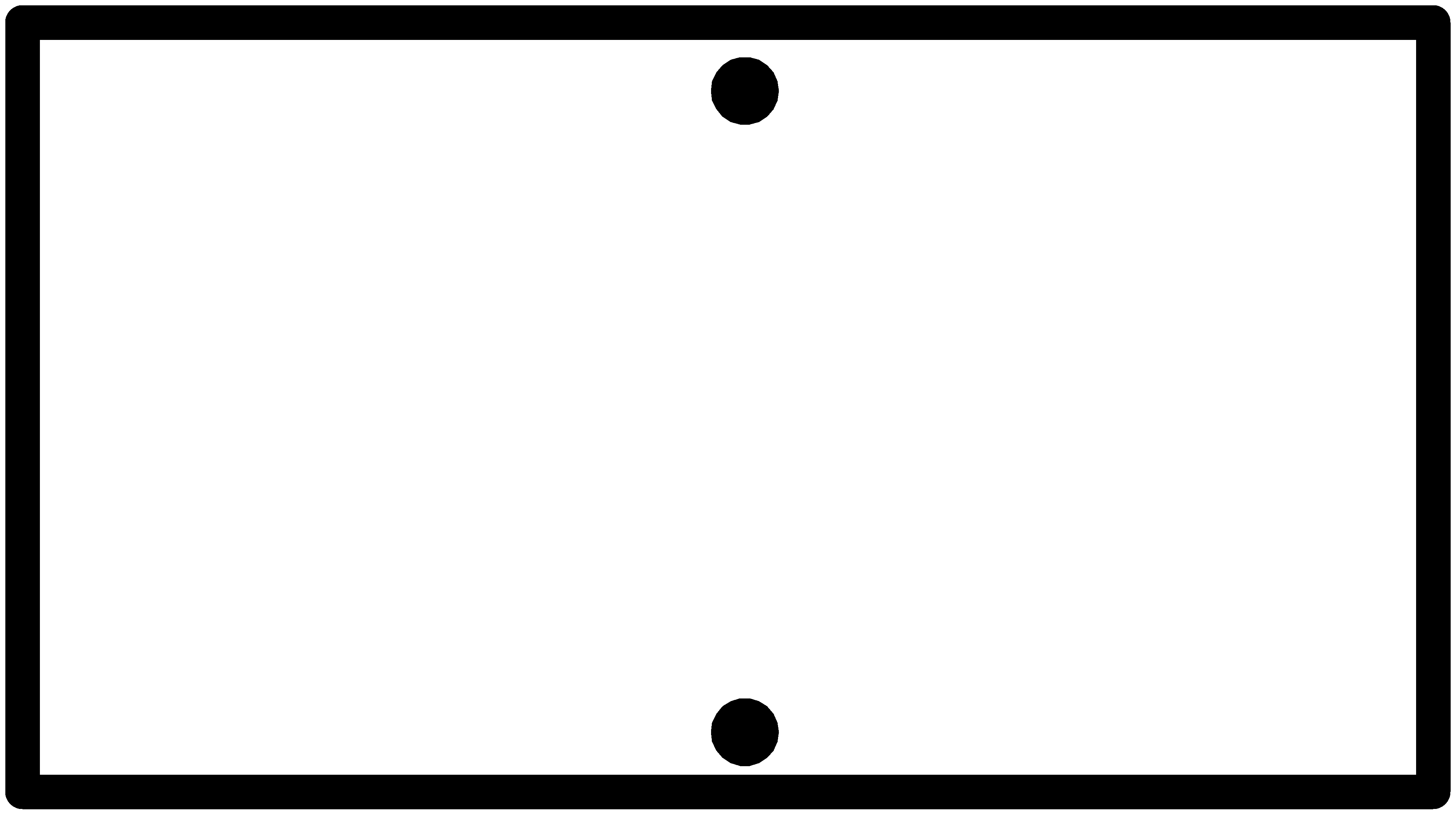
- LEDs Board In order for the microcontroller to be able to control the LEDs, a PMOS is there.
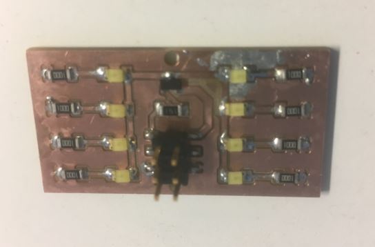
|
-
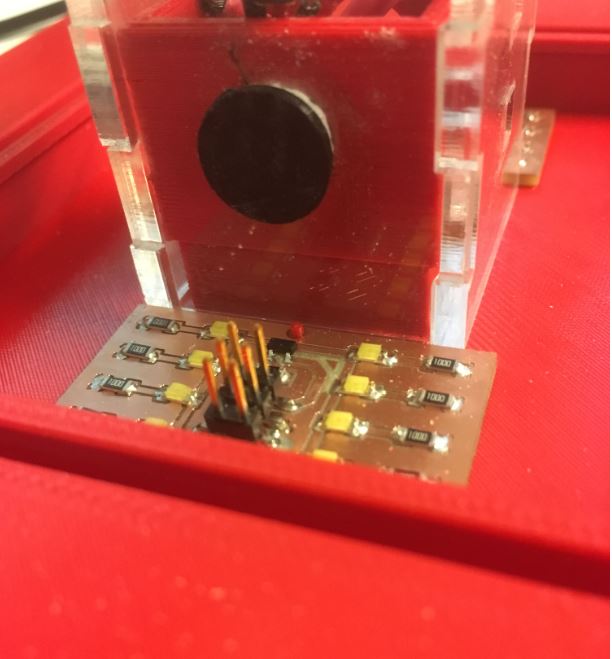
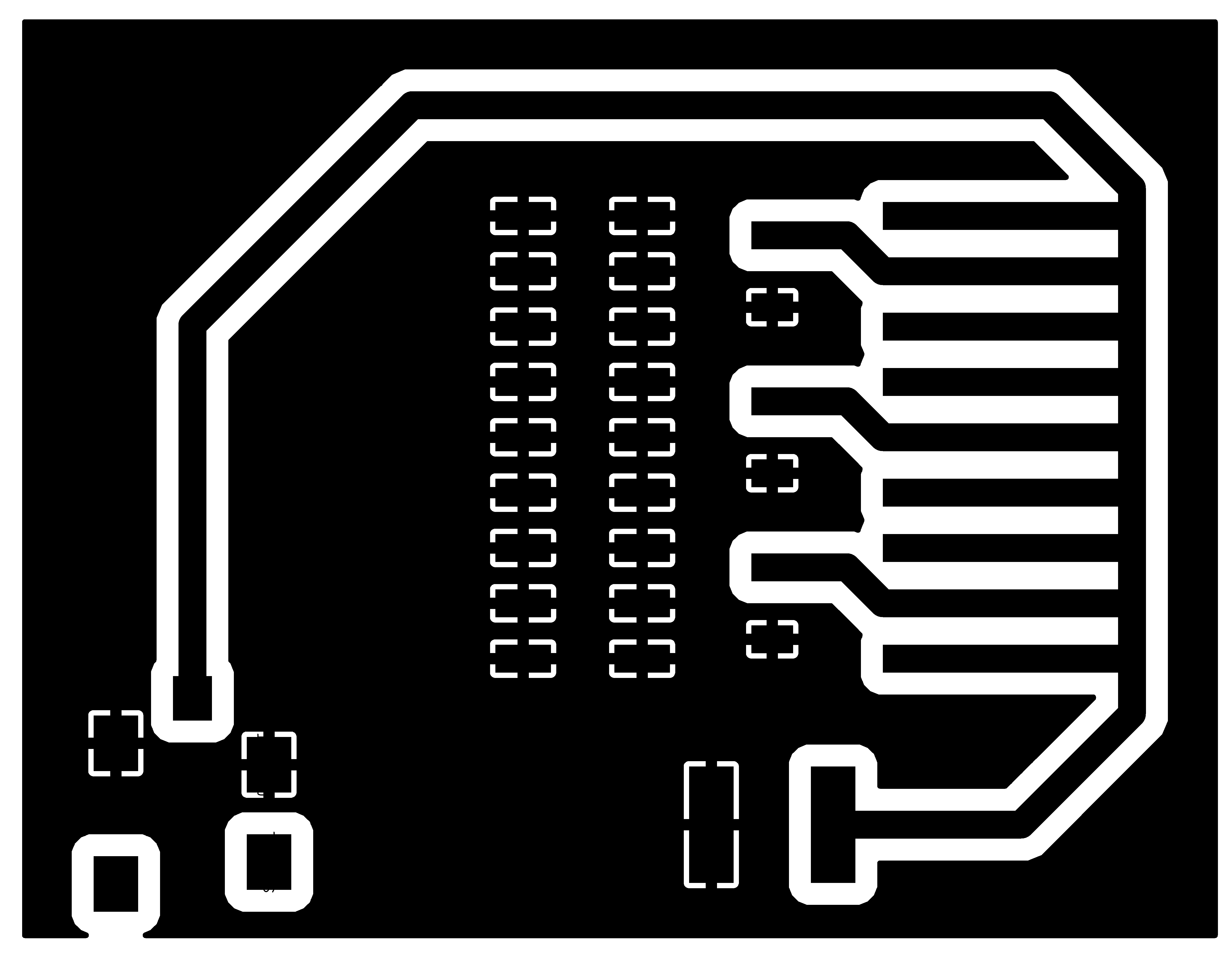
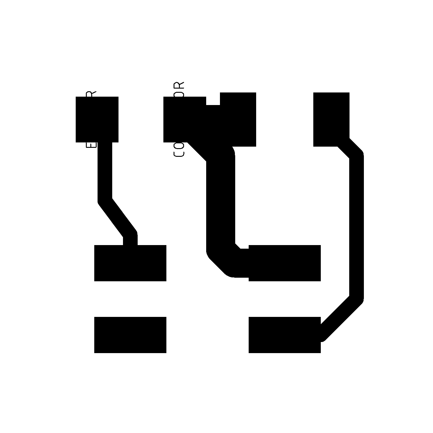
Light Sensor This board is used for the auto on/off feature.
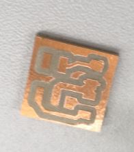
Bare PCB of the Light sensor -
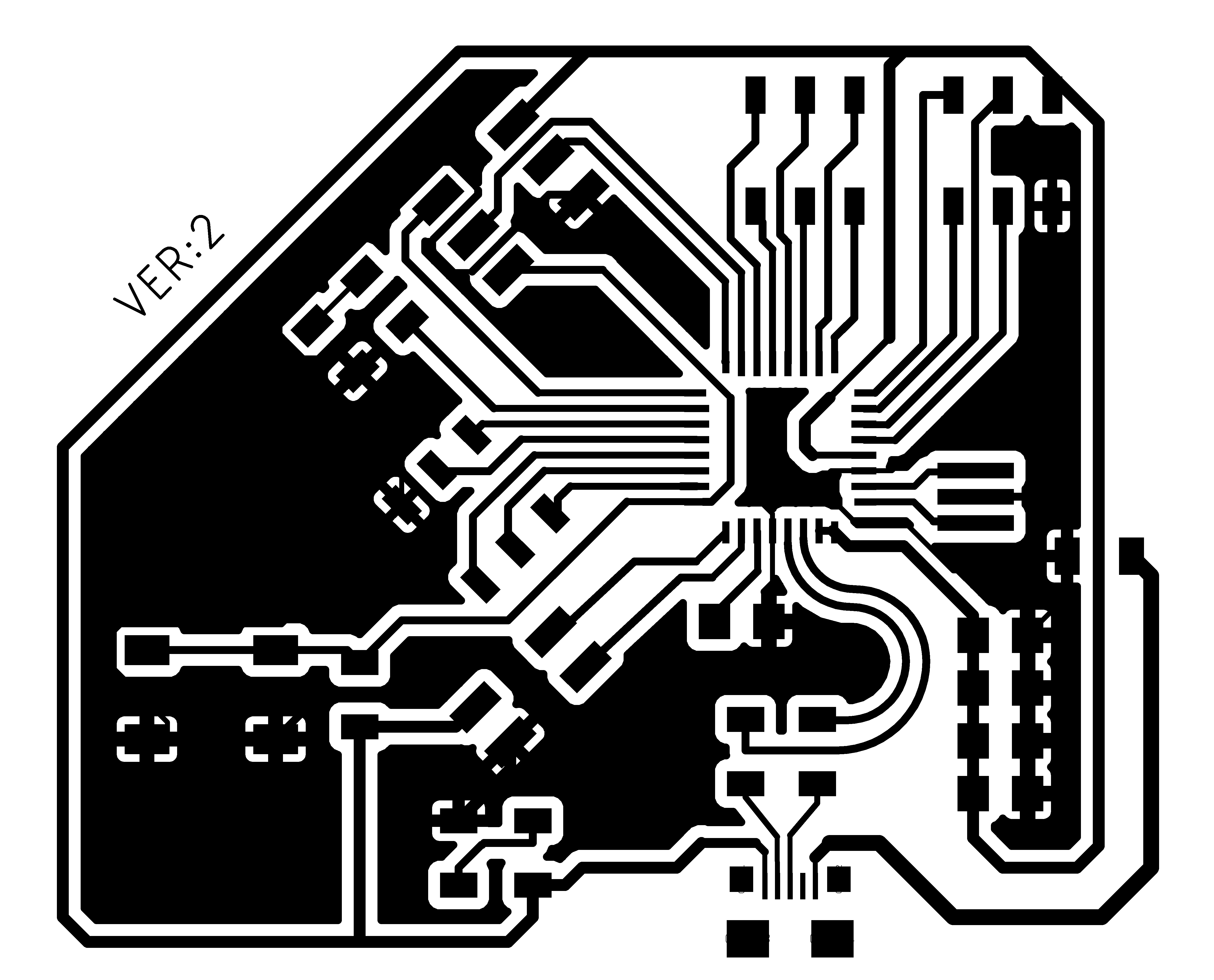
Atmega16U2 board
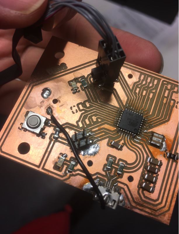
Partially stuffed Atmega16U2 board. Check week12 documentation for details.
Testing
RBG LEDs and OLED display were tested independently. The Atmega16U2 board has been used for multiple assignments, so it is well tested. For the RGB LEDs, I used light_ws2812 library. For OLED display, I used the Adafruit_SSD1306 library.
|

|
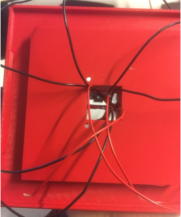
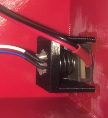
Assembly
|
|
|
|
License
Licensing the software is bit difficult. In my project, I have used some code which is developed by myself so of course I can use whatever license I want. On the other hand, there are code snippets and libraries which are under MIT, BSD, and GPL V3 licenses.
For the documentation (images, videos etc.,), I will use the CC BY 4.0 license.
Bill of Materials
| Part | Value |
Quantity |
Price ($) |
|---|---|---|---|
| Microcontroller |
ATMEGA16u2 | 1 | 3.53 |
| Resonator | 8 MHz | 1 | 0.25 |
| WS2812B |
28 | 5.1 | |
| Bluetooth Module | HC-06 | 1 | 3 |
| OLED Display | SSD1306 | 1 | 2 |
| LEDs | White (160-1737-1-ND) | 16 | 5.5 |
| Phototransistor | 940nm Top View 1206 visible | 1 | 0.15 |
| PMOS | NDS356APCT-ND | 2 | 0.7 |
| Power Plug | CP-012-ND | 1 | 0.8 |
| Power Jack | CP1-023PJCT-ND | 1 | 0.8 |
| Capacitors | Assorted | ≈20 | 1 |
| Resistors | Assorted | ≈30 | 0.3 |
| Switch | SW262CT-ND | 1 | 0.74 |
| Wires | Assorted | ≈1m | 1 |
| Acrylic | ≈930 sq.cm. | 5 | |
| ABS Plastic | ≈200 cubic cm. | 10 | |
| Total | ≈40€ | ||
Further Development
As I am lacking a working Bluetooth module (my guess is that the module died due to an ESD event), features like wake up alarm via phone, time display etc., are missing. Furthermore, how to build an iPhone app without having an access to an apple computer is also a mystery.
Evaluation
As stated earlier also, my main objective of joining the Fab Academy program was to build my skills related to 3D design and fabrication. On that front, I have learned a lot. As my background is in embedded design, I do not consider lack of software functionality as detrimental to the success of the project. Given these facts, I do consider the project to be a success even though it lacks a lot of originally planned features.
Files
- 2D Designs
- PDF files
- SVG files
- 3D Designs
- STL files
- Fusion files
- Electronics Production
- Power Board
- LED Board
- Light Sensor Board
- Atmega16U2
- Software

This work is licensed under a Creative Commons Attribution 4.0 International License.