9. Embedded programming
Abstract
Week09 start with reading microcontroller datasheet. Just started to remember some of my old academic electronics about microprocessor, microcontroller, digital signal processing, FPGA, VLSI, VHDL and so on. This week I need to read about AVR processor, ATtiny44A which I have used for the development of USB programmer and microcontroller board for checking the program in week05 and week07 respectively. As part of my assignment, I need to program my echo hello-world bord developed in the week07 using the programmer developed in week05. Followed by checking the programmed board. For group assignment, we compare the workflows of other architecture.
Individual Assignment
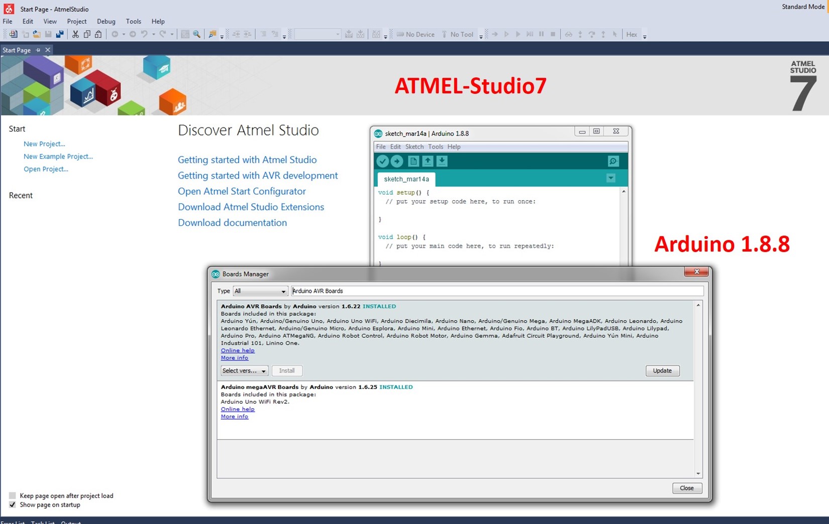
This week I read the ATtiny 44A microcontroller datasheetand learn how to do its architectural features which support the program. Also, I have programmed my hello world board by using Atmel Studio 7.0 and Arduino 1.8.8. Downloaded windows ZIP for non-admin install. See the screenshot of installed files below,
I started to learn something about the embedded system; it is a dedicates computer system designed for one or more specific task. The microprocessor is a CPU on a single chip while; microcontrollers consist of CPU, Memory and I/Os. The microcontroller is extremely slow when comparing to Microprocessor. Then, I started to check the features of ATtiny44A. It is a high-performance, low power CMOS IC. It is an 8-bit AVR microcontroller with 2K/4K bytes In-system Programmable Flash. Which means that CPU or ALU can process 8-bit data at a time. Means it has to take 8 bit-data from the memory which it has to process. Thus, Each location in memory is 8 bit and the data bus also 8-bit. Registers in RAM has to be 8-bit for temporary storage of results. The main features are listed below,
-
120 powerful instructions (Single clock cycle execution)
-
32x8 general purpose working registers with a fully static operation
-
100,000 write/erase cycle (Endurance)
-
128/256 bytes of in-system programmable EEPROM
-
Data storing capacity 20 years at 85 °C/100 years at 25 °C atmosphere
-
One 8-bit and One 16-bit Timer/Counter with Two PWM Channels, Each
-
10-bit ADC
-
Internal and External Interrupt Sources
-
Twelve Programmable I/O Ports
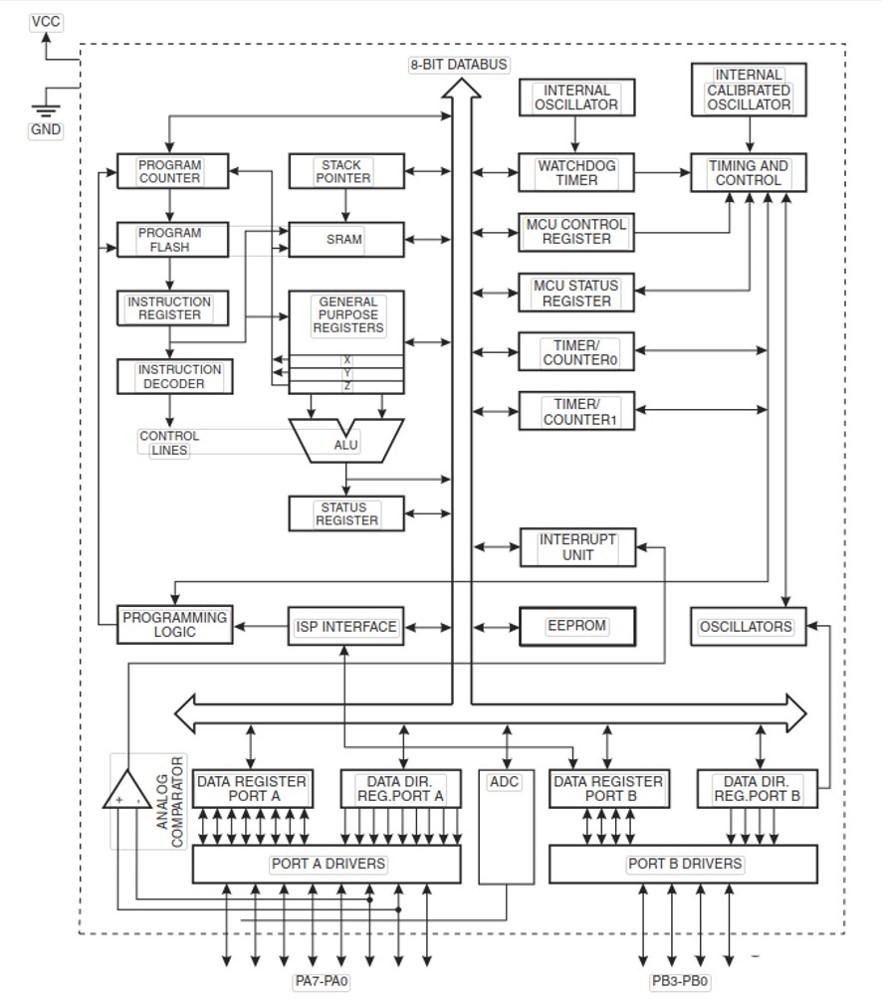
The ATtiny44A achieves throughputs approaching 1 MIPS per MHz allowing the system designer to optimise power consumption versus processing speed. The figure below shows the block diagram; The resulting architecture is more code efficient while achieving throughputs up to ten times faster than conventional CISC microcontrollers. Its operating voltage is 1.8-5.5V. We used the speed grade of 20 MHz at 4.5-5.5 V.
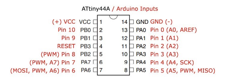
It is a 14 pin SOIC, see the pin configuration below,
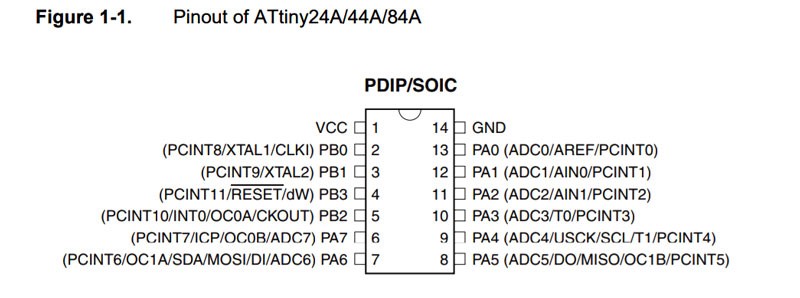
The pin configurations are listed below,
-
VCC (Supply Voltage)
-
GND (ground)
-
PORTA (8-bit) named as PA7-PA0 (Bi-directional I/O port with internal pull-up resistors)
-
4-pin PORTB named as PB0-PB3 (Bi-directional I/O port with internal pull-up resistors)
-
The direction of pins is defined by data direction register that is DDRA and DDRB
-
Data is written to an output pin using registers PORTA and PORTB
Also, check AVRFREAKS pages to understand the basic concept of programming with digital logic for efficient C coding for AVR. After going through the datasheet get an overview of my IC how it is organised for the efficient working platform. I thought this is the best time for switching the program for my microcontroller. I connected the programmer, microcontroller board, ISP programming cable, FTDI to USB connector for microcontroller connections. Below figure shows the schematic layout of the microcontroller board to check the ports and pins for the input and outputs for the codes.
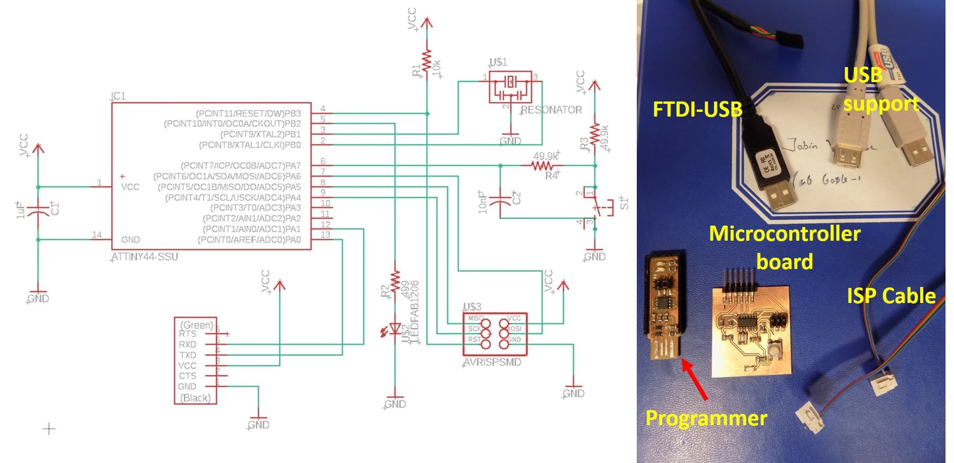
The button is connected to PA7 (IC pin No:6) [Arduino IDE pin is 7].
Similarly, LED is connected to PB2 [Arduino IDE the pin is 8]. I started to do programming Echo Hello-World board in Atmel Studio 7, which is downloaded and installed previously as shown above. There are several ways to program the AVR microcontroller. Easiest one is Arduino IDE and Atmel Studio with toolchain in GCC. First, I am planning to use Arduino IDE and later on using Atmel studio. I have my programmer USBTiny ISP using for the program my microcontroller.
Arduino IDE based programming
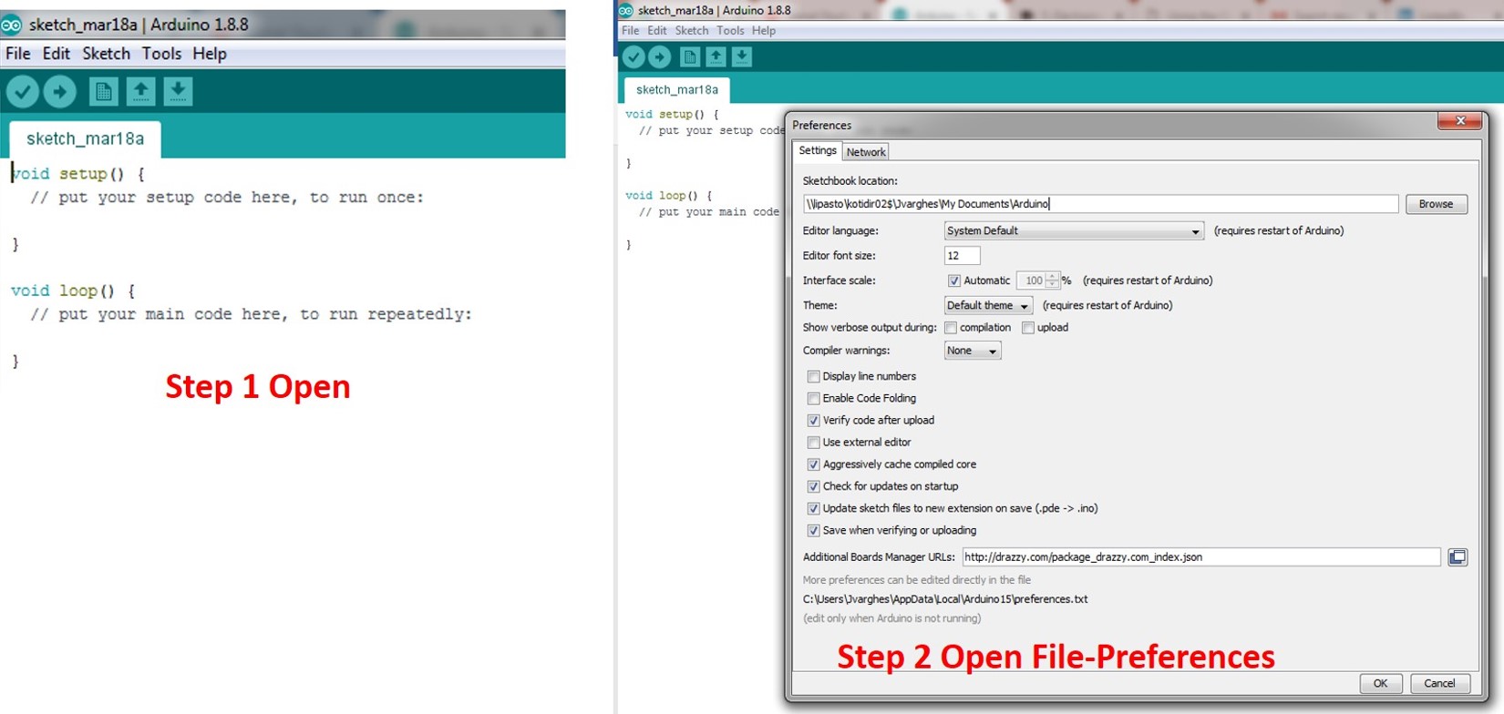
Arduino is an open-source electronics platform based on hardware and software. Easy for making interactive projects. Arduino was born at the Ivrea Interaction Design Institute as an easy tool for fast prototyping, aimed at students without a background in electronics and programming. The initial setting for the Arduino IDE is shown below. I used Arduino 1.8.8 download the zip file and extracted and open the Arduino.exe file for initial settings. Open File-Preferences-Browse Sketchbook location and select Arduino- Additional boards Manager URLs http://drazzy.com/package_drazzy.com_index.json and click OK. No change in the Network.
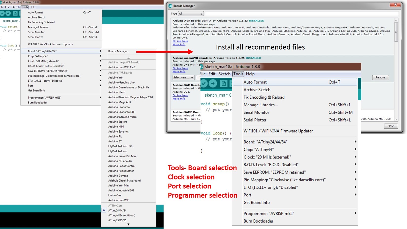
Followed by Tool selections, open tools and followed by select the program environment as shown in the figure based on your programmer and board.
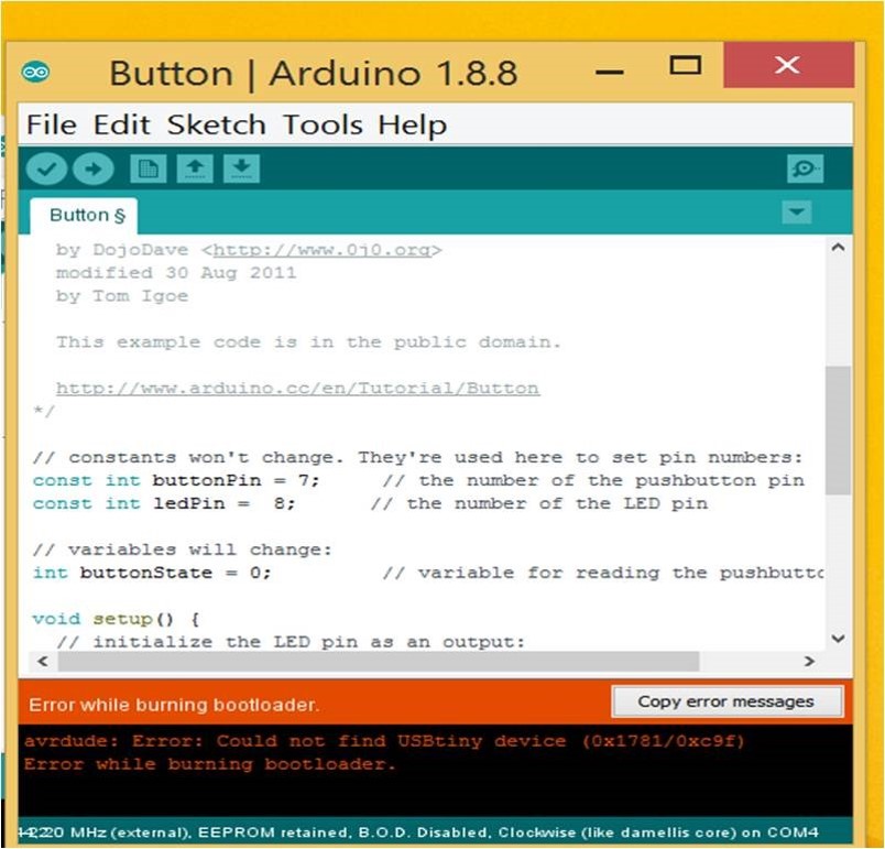
From Arduino file-examples-digital-Button selected for the program it. Moreover, followed by changing the pin of Button number to 7 and LED pin to 7 in the Arduino button program.
Then I verified and moved for the Burn boot loader. I receive Error while burning bootloader as shown in the figure below,
Then, I check all my connections; Our local instructor has given Atmel ICE programmer to check whether microcontroller recognises or not. Unfortunately, it shows the voltage but fails to enter programming mode. See the figure below about the Error associated with it.
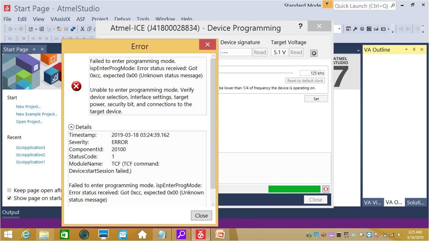
I started to verify device selection, interface settings, target power, connection to target power, etc. Resonator 1 pin does not have continuity with the place where it attached. Then solder the resonator but still, the error remains. Then I decided to change the controller and check again for solutions. Still, I receive the error message. My board is broken, I decided to do with milling a new microcontroller board for programming.
Atmel Studio based programming
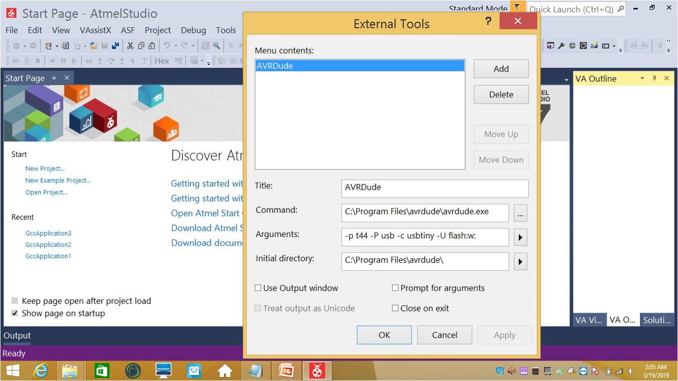
The installation procedures are described above about Atmel studio 7.0 with a link. I started to programming my microcontroller board using Atmel studio7. I open the Atmel Studio and add AVRDude tool automatically. Tools-External Tools set it like in the below figure and apply OK
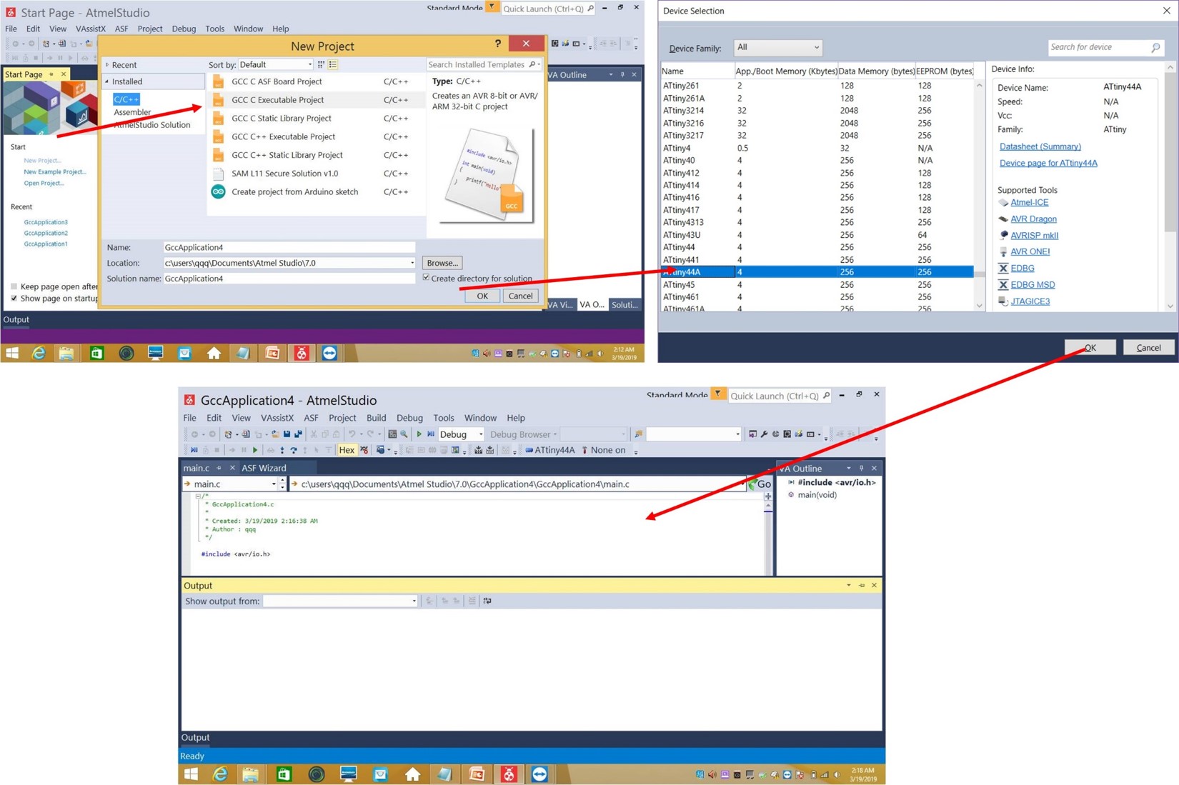
Next step is to start a new project, Files-New-Project, select the type as GCC C Executable Project, followed by Device Family selection that is ATtiny 44A and press OK. This will open a main.c program window. Below screenshot present, the following steps described above,
I have less experience in C coding; then I learn to understand the coding by previous year documentation. I selected Ivan’s c code which is explained clearly. Then, I started to code my self and is given below,
/*
* Jobin microcontroller.c
* Created 1932019: 11:44AM in Finland
* Author: Jobin Varghese
*/
#ifndef F_CPU
#define F_CPU 20000000UL // 20 MHz clock speed
#endif
#include <avr/io.h> //Library to handle avr inputs and outputs
#include <util/delay.h> // Library to add delays. Necessary for blinking.
int main(void)
{
DDRB = DDRB | (1 << PB2); // DDRB Port B Data Direction Register. Selects direction of pins  // In this case PB2 is an ouptut
DDRA = DDRA & ~(1 << PA7);      //Set PA7 as input
while (1)
{
//Check if button is pressed (its value is 0 because the button has a PULL-UP resistor) uint8_t val = PINA & (1 << PA7);
if(!val){           //Turn the LED on
PORTB = PORTB | (1<<PB2);
}
else -{         //Turn the LED off
PORTB = PORTB & ~(1<<PB2);
}
}
}
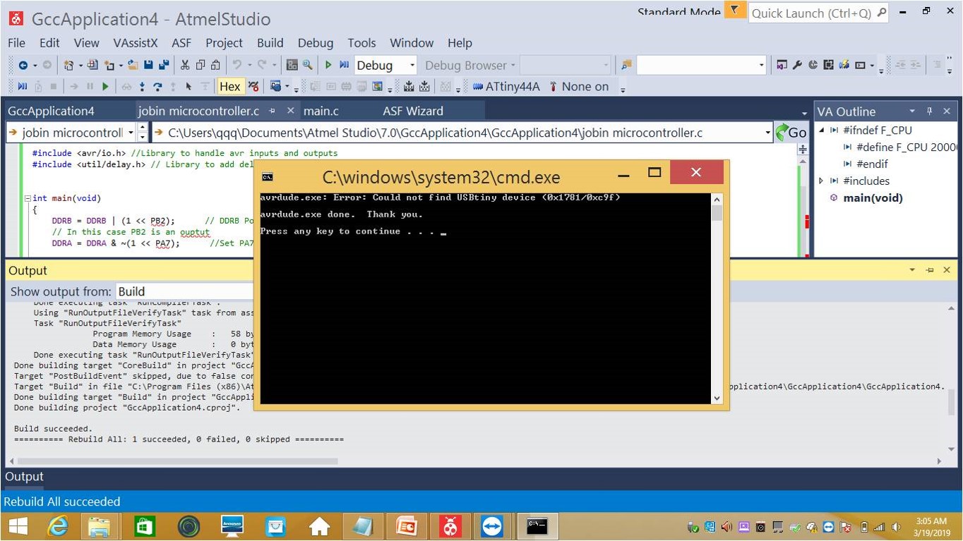
I sucessfully compile and build my code, unfortunatly, I got the same error message as similar to that of Arduino IDE process. See the Error report in the below figure,
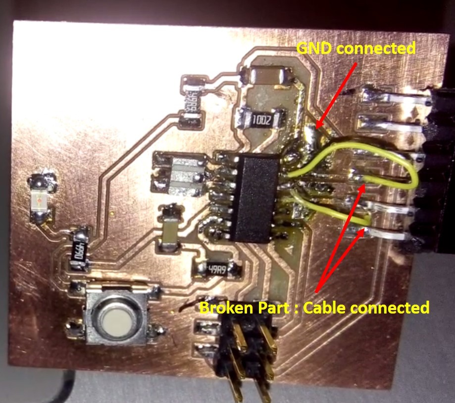
Then, I started to check my board before milling the new board. I found the ground issue also mentioned in the [week 07 ] (http://fabacademy.org/2019/labs/oulu/students/jobin-varghese/assignments/week07/), In the case of the new board during the changing ATtiny 44A. I desolder all IC pins during that time I forget to connect the ground to the IC. The broken connection I manage to connect it with 2 extra cables to avoid short during the operation. See the figure below,
 First tried Arduino, examples LED blink without delay, I change LED pin number 8 in the program.
  /*
  Blink without Delay

  Turns on and off a light emitting diode (LED) connected to a digital pin,
  without using the delay() function. This means that other code can run at the
  same time without being interrupted by the LED code.

  The circuit:
  - Use the onboard LED.
  - Note: Most Arduinos have an on-board LED you can control. On the UNO, MEGA
    and ZERO it is attached to digital pin 13, on MKR1000 on pin 6. LED_BUILTIN
    is set to the correct LED pin independent of which board is used.
    If you want to know what pin the on-board LED is connected to on your
    Arduino model, check the Technical Specs of your board at:
    https://www.arduino.cc/en/Main/Products

  created 2005
  by David A. Mellis
  modified 8 Feb 2010
  by Paul Stoffregen
  modified 11 Nov 2013
  by Scott Fitzgerald
  modified 9 Jan 2017
  by Arturo Guadalupi

  This example code is in the public domain.

  http://www.arduino.cc/en/Tutorial/BlinkWithoutDelay
*/

// constants won't change. Used here to set a pin number:
const int ledPin =  8;// the number of the LED pin

// Variables will change:
int ledState = LOW;             // ledState used to set the LED

// Generally, you should use "unsigned long" for variables that hold time
// The value will quickly become too large for an int to store
unsigned long previousMillis = 0;        // will store last time LED was updated

// constants won't change:
const long interval = 1000;           // interval at which to blink (milliseconds)

void setup() {
  // set the digital pin as output:
  pinMode(ledPin, OUTPUT);
}

void loop() {
  // here is where you'd put code that needs to be running all the time.

  // check to see if it's time to blink the LED; that is, if the difference
  // between the current time and last time you blinked the LED is bigger than
  // the interval at which you want to blink the LED.
  unsigned long currentMillis = millis();

  if (currentMillis - previousMillis >= interval) {
    // save the last time you blinked the LED
    previousMillis = currentMillis;

    // if the LED is off turn it on and vice-versa:
    if (ledState == LOW) {
      ledState = HIGH;
    } else {
      ledState = LOW;
    }

    // set the LED with the ledState of the variable:
    digitalWrite(ledPin, ledState);
  }
}
See the video file,
<
After this program, I started to do for button and LED simultaneously. For that, I choose button program in Arduino examples and change button pin- 7 and LED pin-8
/*
  Button

  Turns on and off a light emitting diode(LED) connected to digital pin 13,
  when pressing a pushbutton attached to pin 2.

  The circuit:
  - LED attached from pin 13 to ground
  - pushbutton attached to pin 2 from +5V
  - 10K resistor attached to pin 2 from ground

  - Note: on most Arduinos there is already an LED on the board
    attached to pin 13.

  created 2005
  by DojoDave <http://www.0j0.org>
  modified 30 Aug 2011
  by Tom Igoe

  This example code is in the public domain.

  http://www.arduino.cc/en/Tutorial/Button
*/

// constants won't change. They're used here to set pin numbers:
const int buttonPin = 7;     // the number of the pushbutton pin
const int ledPin =  8;      // the number of the LED pin

// variables will change:
int buttonState = 0;         // variable for reading the pushbutton status

void setup() {
  // initialize the LED pin as an output:
  pinMode(ledPin, OUTPUT);
  // initialize the pushbutton pin as an input:
  pinMode(buttonPin, INPUT);
}

void loop() {
  // read the state of the pushbutton value:
  buttonState = digitalRead(buttonPin);

  // check if the pushbutton is pressed. If it is, the buttonState is HIGH:
  if (buttonState == HIGH) {
    // turn LED on:
    digitalWrite(ledPin, HIGH);
  } else {
    // turn LED off:
    digitalWrite(ledPin, LOW);
  }
}
See the video file,
Group assignment
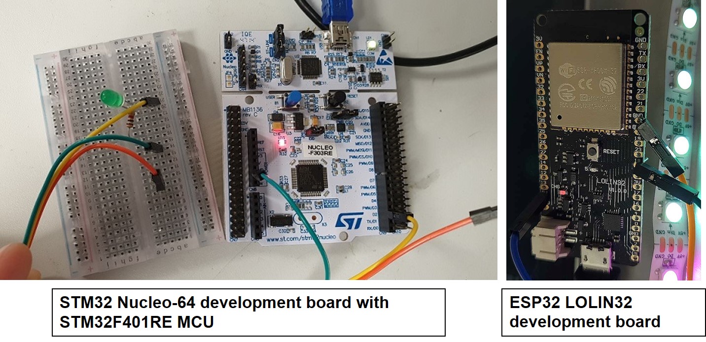
We worked together with the whole Oulu Academy group. We tested the STM32 Nucleo-64 development board with STM32F401RE MCU and ESP32 LOLIN32 development board using Arduino IDE. ST32 is a family of 32-bit microcontroller integrated circuits by STMicroelectronics. this group is related to same 32 bit ARM processor. The STM32 F4-series is the first group of STM32 microcontrollers based on the ARM Cortex-M4F core. The F4-series is also the first STM32 series to have DSP and floating point instructions. The F4 is pin-to-pin compatible with the STM32 F2-series and adds higher clock speed, 64 KB CCM static RAM, full duplex, improved real-time clock, and faster ADCs. All devices offer one 12-bit ADC, a low-power RTC, six general-purpose 16-bit timers including one PWM timer for motor control, two general-purpose 32-bit timers. They also feature standard and advanced communication interfaces.
- Up to three I2Cs
- Up to four SPIs
- Two full duplex I2Ss. To achieve audio class accuracy, the I2S peripherals can be clocked via a dedicated internal audio PLL or via an external clock to allow synchronization.
- Three USARTs
- SDIO interface
- USB 2.0 OTG full speed interface
See the data sheet STM32F401x for more information,
While, ESP32 is a series of low-cost, low-power system on a chip microcontrollers with integrated Wi-Fi and dual-mode Bluetooth. The ESP32 series employs a Tensilica Xtensa LX6 microprocessor in both dual-core and single-core variations and includes in-built antenna switches, RF balun, power amplifier, low-noise receive amplifier, filters, and power-management modules. ESP32 is created and developed by Espressif Systems, a Shanghai-based Chinese company, and is manufactured by TSMC using their 40 nm process. See the more details about ESP32 LOLIN32 in the link.
First, we install the Board manager for STM32F4 Boards ,followed by defining the board information in tools similar steps as that of ATtiny 44A board programming. Select board Nucleo-64, board part number Nucleo F303RE and run the blinking test code for the board setup.
See the video after programming the STM32F4 board,
<
First installing ESP32 board in Arduino IDE, detailed instructions see this Tutorial link . Similar steps followed (see the individual assignment) for programing the ESP32 LOLIN32 development board. See the below first picture present STM32F4 and second picture which present LED blinking programmed for ESP32 board using Arduino IDE.
Summary
I learned the basics of embedded programming in Arduino and Atmel studio. My microcontroller board is working in both Arduino and Atmel studio. As part of the group assignment, we compare the performance and development workflow for other architecture STM32 and ESP32.
What questions do you have? - Still, I am lagg in programming, my final project contain microcontroller based AC to DC converter. What would you like to learn more about? -I would like to learn more about AC to DC convertion using bridge rectifier and microcontroller to regulate the DC voltage to power storage device.