11. Input devices
Abstract
This week, I am planning to do my input hall effect sensor for the development of bicycle speedometer which is in my final project. Which include microcontroller board to sense my input magnetic sensor. I designed an input device microcontroller board and fabricated and tested.
Individual assignment
My assignment which is related to my final project idea of the bicycle energy harvester. In this project bicycle speedometer is one input device. Magnetic switch developed in the 1930s which is working similar to delay, closing an electrical contact in the presence of a magnetic field. Advantages of magnetic switches over conventional relay include lower contact resistance, faster-switching speed and longer life. The switch is sealed to eliminate sparking hazards in a flammable or explosive environment.
Board design and fabrication
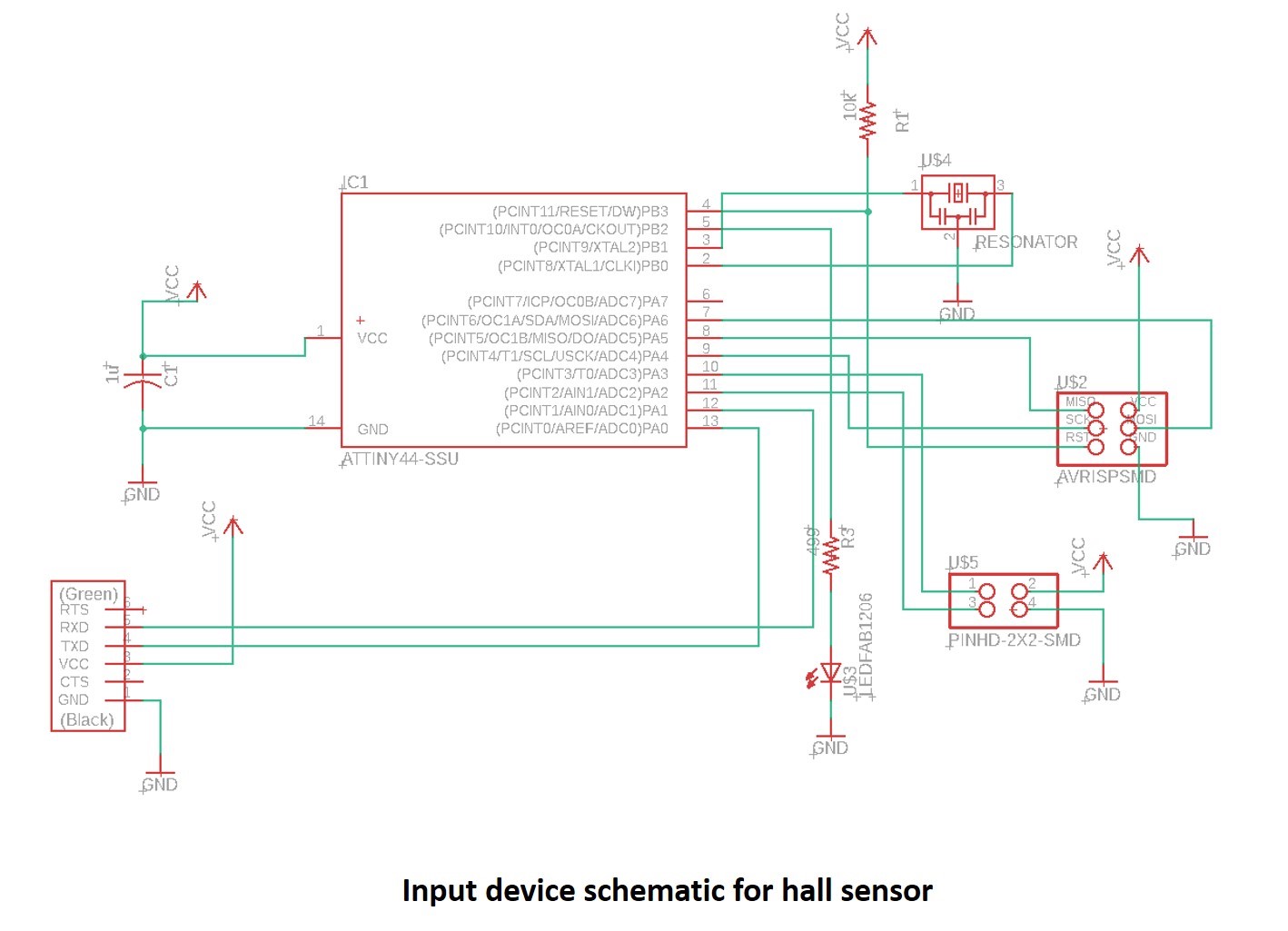
I have designed a new schematic for my input device board using Attiny 44A with one LED and 2x3 Pin header. I follow the previous week07 assignment for following the design rules. I don’t repeat the design workflow and circuit board design and fabrication, which is clearly explained in the electronic design week07. I carefully follow the instructions for design workflow, circuit board design and fabrication.
See the board schematic in the below figure,
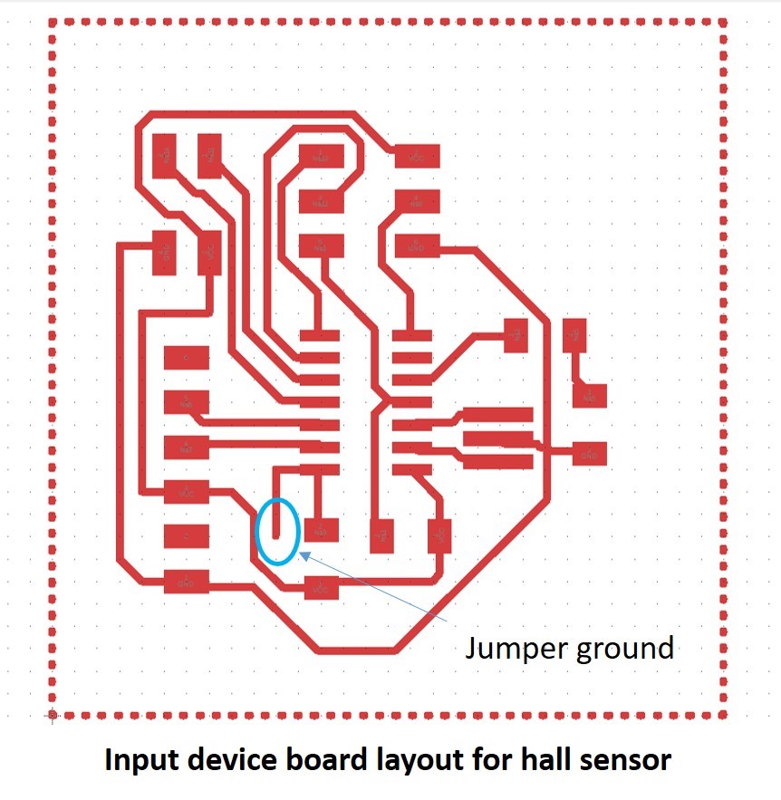
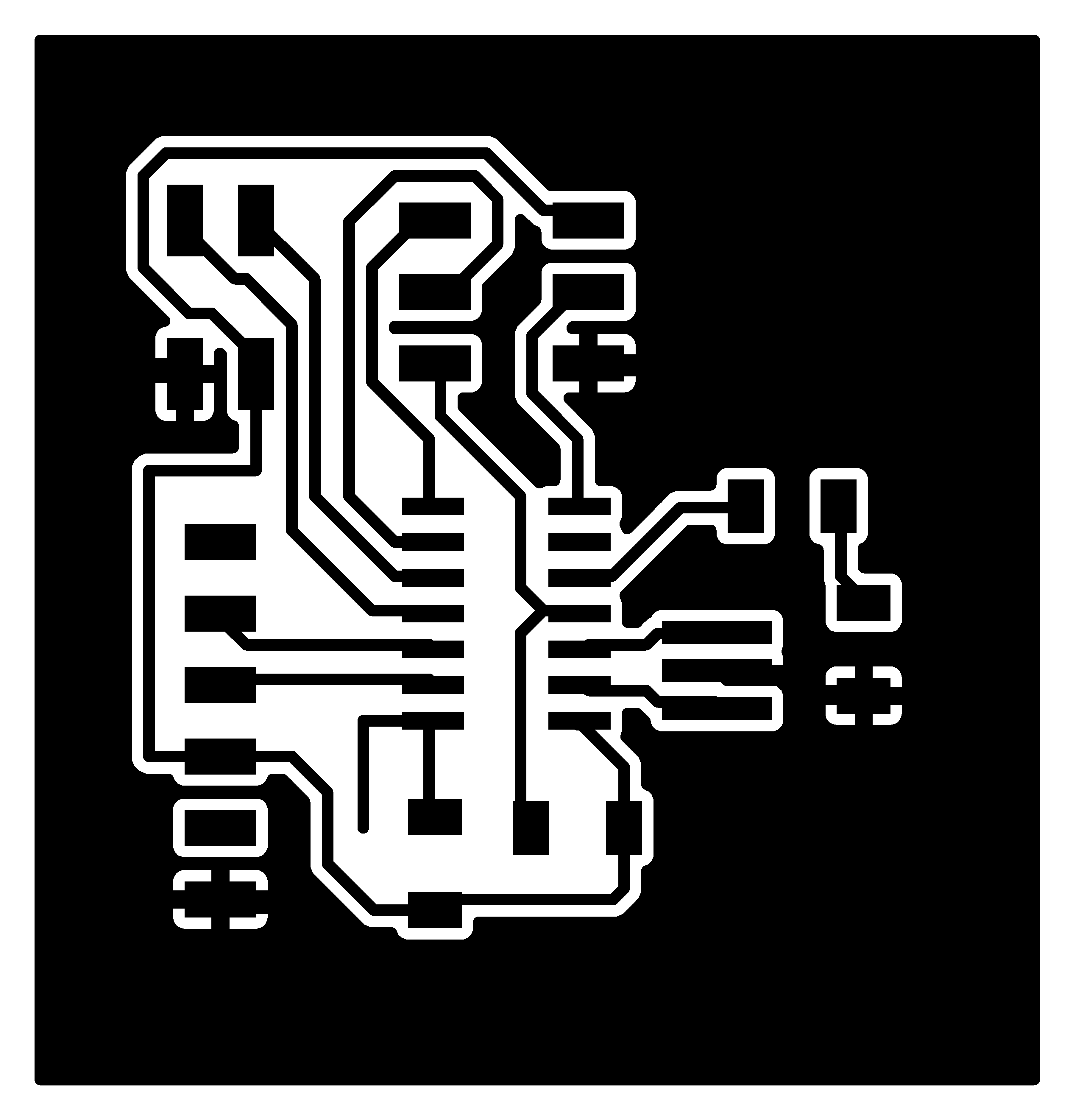
See the below figure of the board layout.
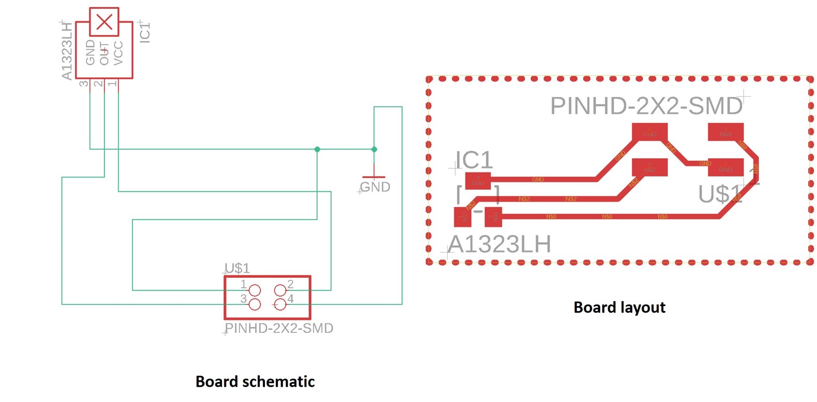
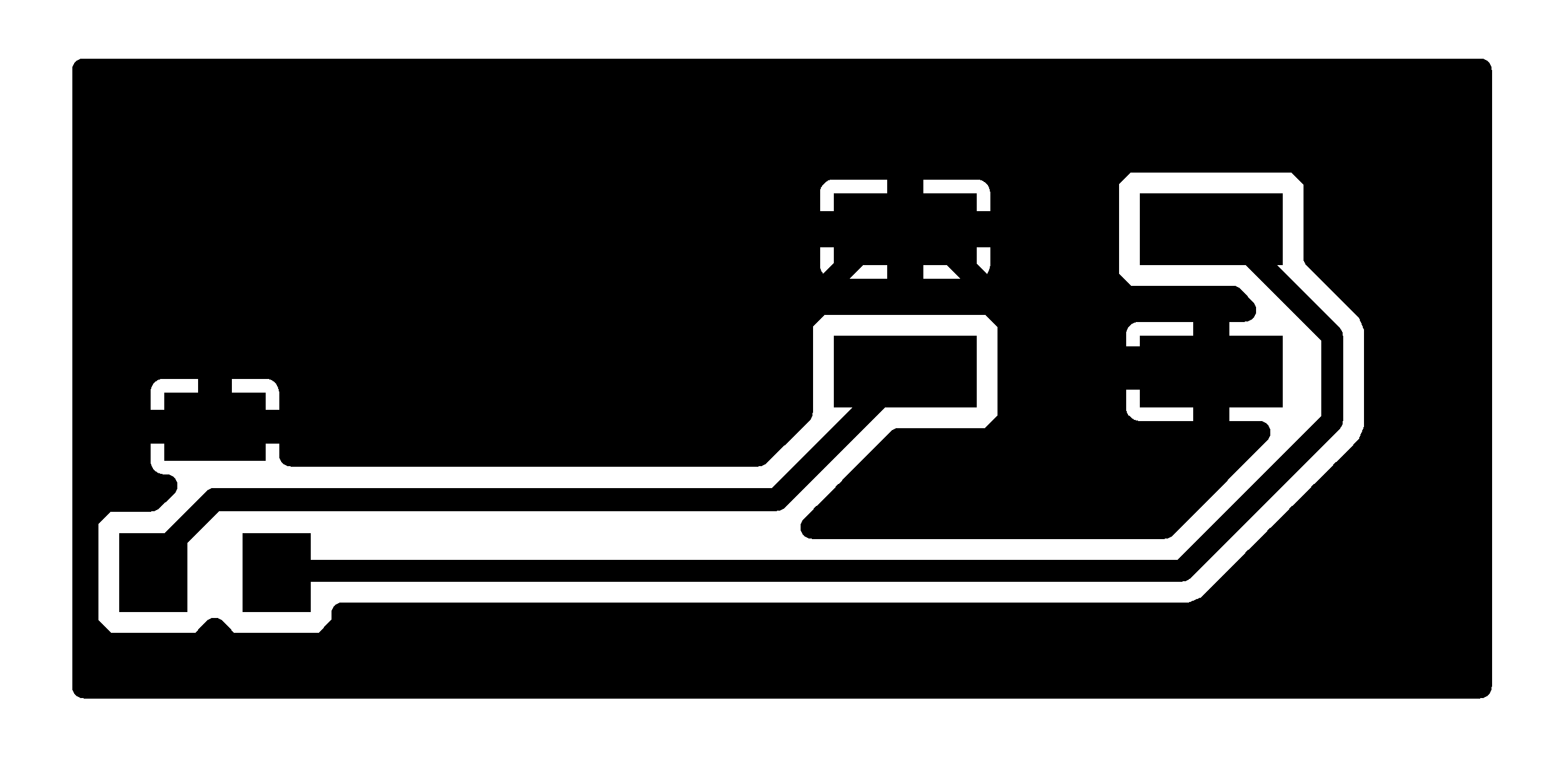
Also, plan to design a separate sensor board schematic and board layout. See the schematic and board layout in the below figure,
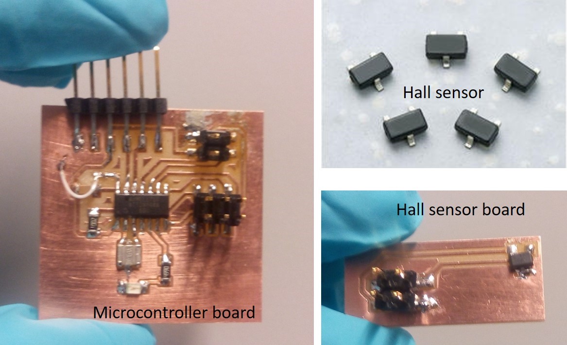
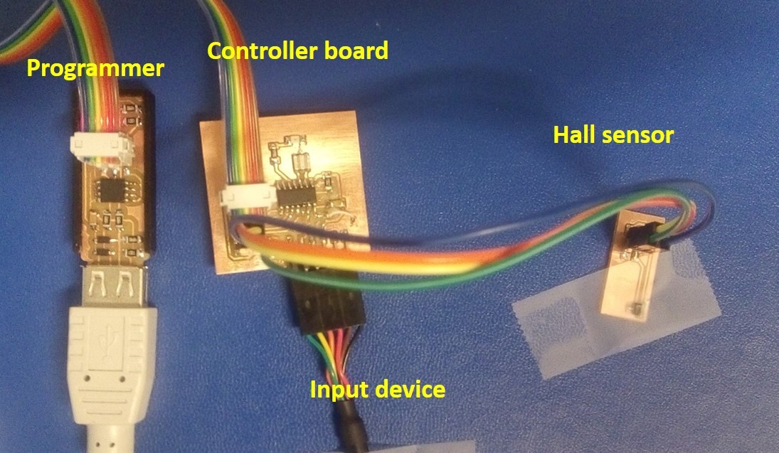
For milling and soldering, I refer my old assignments such as week05, and week07. Below figure shows the final milled and soldered board with all the components in the schematic. I used A3245 series which is rated for operation between the ambient temperatures –40°C and 85°C for the E temperature range, and –40°C to 150°C for the L temperature range. The small geometries of the BiCMOS process allow these devices to be provided in ultrasmall package. Package LH is a SOT23W, a miniature low-profile surface-mount package. It is lead (Pb) free, with 100% matte tin plated leadframe. A Hall effect sensor is a device that is used to measure the magnitude of a magnetic field. Its output voltage is directly proportional to the magnetic field strength through it. Hall effect sensors are used for proximity sensing, positioning, speed detection, and current sensing applications. In my studies, I used as a speedometer for my bicycle. See the final soldered boards in the below figures.
The connection between the sensor board and the microcontroller is shown here. I used wire ribbon connector with 4 wires connected.
Programming
Further, I copied the microcontroller c code as well as python codes by Neil for the hall switch sensor from the fabacademy site. Also our local instructor Juha suggested some codes which is working with Arduino IDE with serial port read and digital read. Both program work sucessfully. Analog reads are very slow, but it tell u preciesly what the relative voltage is on a pin. While digital reads tells you that the voltage is over or under some present threshold, but it is very fast. I have used Arduino IDE for programming the circuit board developed. The hall sensor code used is modified from the Fabacademy schedules. The implementation and programming protocols are already discussed and documented in week09. I follow the Arduino IDE based programming protocol for my input device week.
See the serial port reading through Arduino IDE,
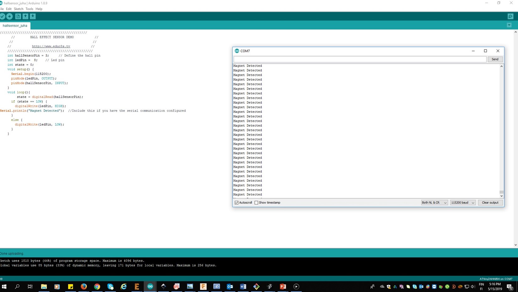
See the below video which shows the digital read for glow the LED when magnet near to the sensor,
Group assignment
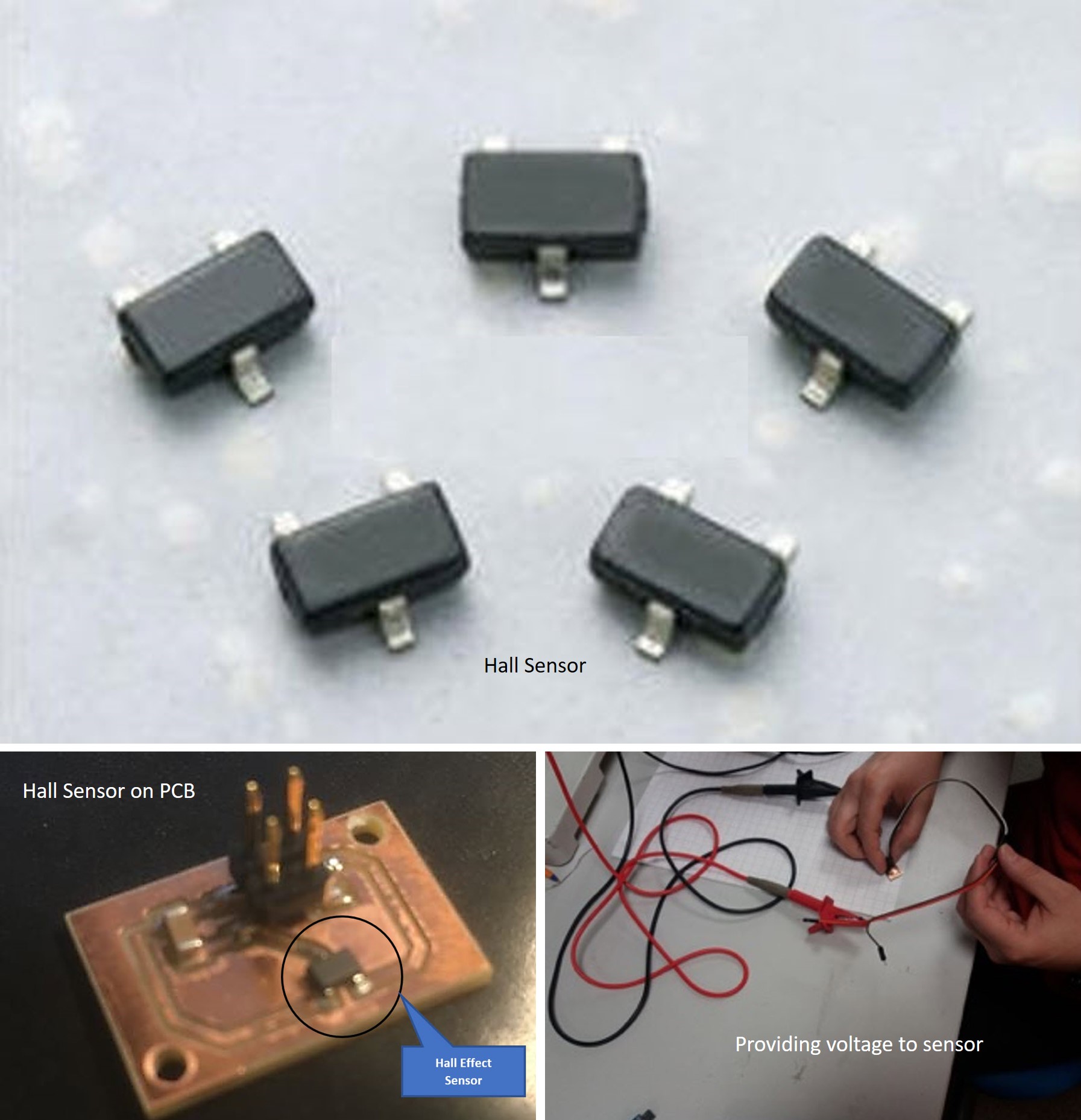
This week my group members are Alok, Sahan, Michael and Yasir For the group work, we use hall sensor analogue outputs with a change in a magnetic field. This group work helps me to do my final project hall sensor for bicycle speedometer. A Hall effect sensor is a device that is used to measure the magnitude of a magnetic field. Its output voltage is directly proportional to the magnetic field strength through it. Hall Effect sensors are used for proximity sensing, positioning, speed detection, and current sensing applications. The Hall Effect sensor that we used was A3245: Chopper-Stabilized Omnipolar Hall-Effect Switch. The A3245 integrated circuit is an omnipolar, ultrasensitive Hall-effect switch with a digital output. This device has an integrated regulator permitting the operation to 24 V, making it the first omnipolar switch available for the operation to 24 V. This device is especially suited for operation over extended temperature ranges, up to +150°C.
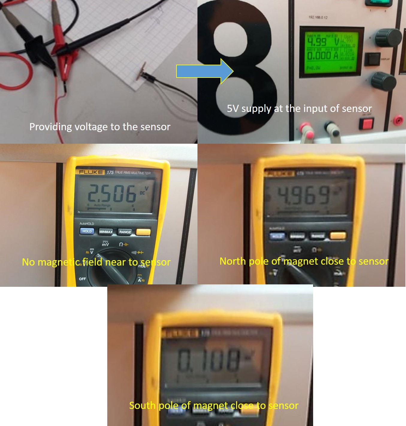
The sensor board was tested by applying 5V power supply across it and measured the resulting voltage at the output of the sensor. The output voltage with no magnetic field nearby was 2.5V. When the north pole of the Magnet was brought close to the sensor, it gave an output voltage of 5V, and when the south pole of the magnet was brought close to the sensor, it gave an output voltage of 0V, This indicated that the sensor was working correctly. See the images below
Summary
This week, I designed an input device microcontroller board and fabricated and tested it.My assignment which is related to my final project idea of the bicycle energy harvester. In this project bicycle speedometer is one input device. Most of problems faced on programing, to locate the pins assigned for hallsensor.
Design Files
- Input Device Board Schematic
- Input Device Board Layout
- Hall Sensor Board Schematic
- Hall Sensor Board Layout
- Input Device Board Outline png file
- Hall Sensor Board png file
- Hall Sensor Board png file
- Hall Sensor Board Outline png file
- Input Device Board Outline rml file
- Hall Sensor Board microcontroller rml file
- Hall Sensor Board rml file
- Hall Sensor Board Outline rml file