14. Networking and communication
This week individual assignment is to design, build and connect wired or wireless nodes with network or bus address. I decided to connect wirelessly to my Attiny 44A board develop during week07. For this assignment, I used HC-06 slave Bluetooth device as the part of network. I install LED controll application to my mobile phone to control the network communication. This week group assignment to send a message between the projects.
Individual assignment
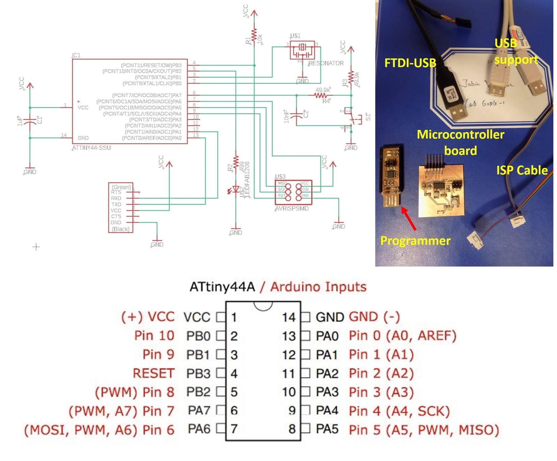
My microcontroller board schematic and corresponding Arduino input pins are shown in the figure below. Which is useful for the programing the network communication.
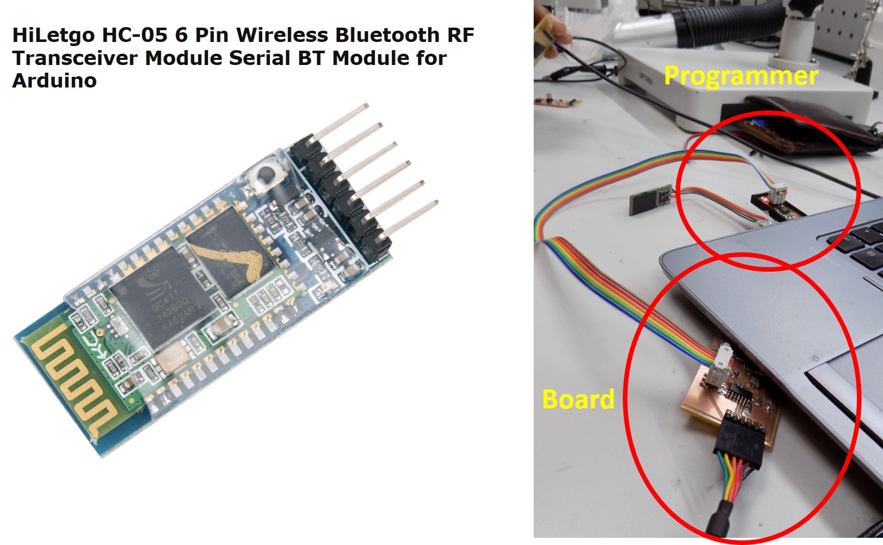
I connected Bluetooth device through FTDI to USB connector connected to laptop, which is already in the board by using Tx, Rx and VCC and GND and power up the module and search the blue tooth module in my phone. Blue tooth device is active and it visible and paired in the phone (Password is 1234). Then, I power the Bluetooth microcontroller board with another controller board via existing ISP connector and FTDI to USB connected to laptop. I use my programmer to program the microcontroller board for demonstrating the network communication. HC-06 Bluetooth Module. It is an easy to use Bluetooth SPP (Serial Port Protocol) module, designed for transparent wireless serial connection setup. Its communication is via serial communication, which makes an easy way to interface with microcontroller. HC-06 Bluetooth module provides switching mode between master and slave mode which means it able to use neither receiving nor transmitting data.
Specification:
- Model: HC-06
- Input Voltage: DC 5V
- Communication Method: Serial Communication
- Master and slave mode can be switched
Figure below shows the Bluetooth module and programming setup for the microcontroller board.
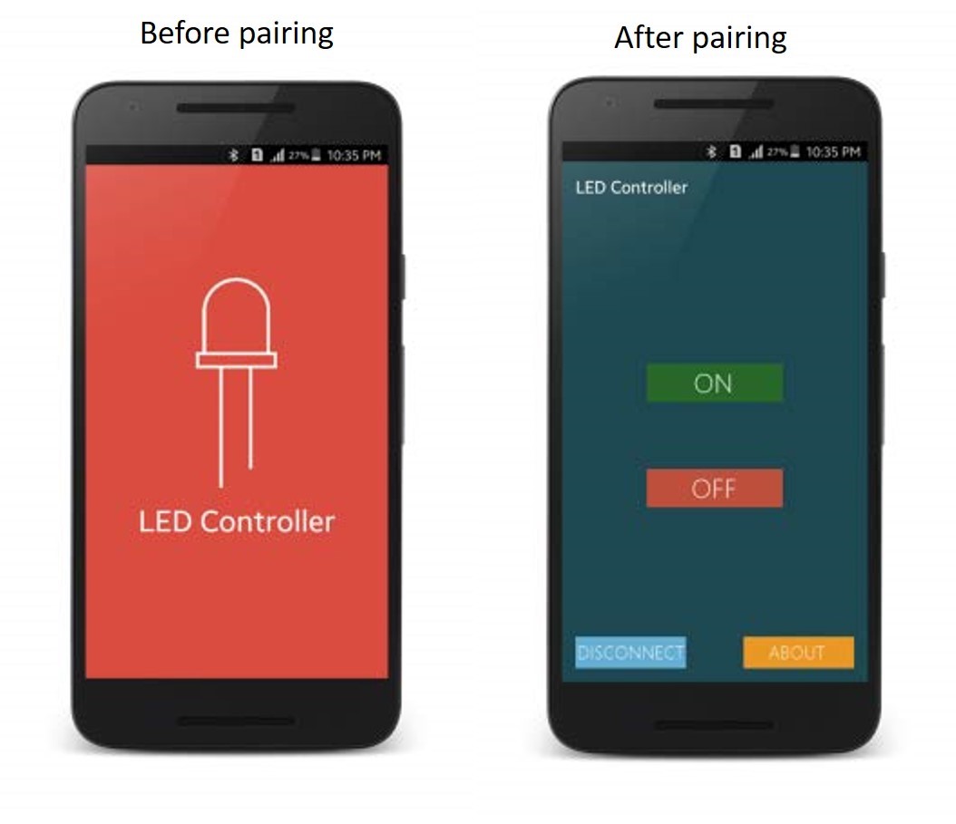
Next step is to download a mobile application for LED controller through Bluetooth. I learned some basics of Arduino Bluetooth basic tutorial to learn the Arduino Pins and Bluetooth pins. That is, Arduino Pin RX (pin 0) to Blue tooth TX pin , Similarly, TX (Pin 1) to RX, then VCC and ground. Based on the pin configuration, I modify one LED-blinking program and build to microcontroller board. Successfully program the microcontroller board. Then, I install the mobile application LED control to my Android phone. See the mobile application figures below,
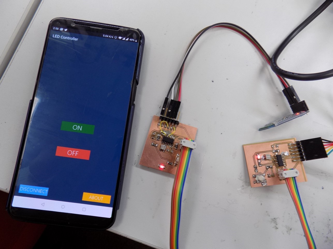
The microcontroller boards and Bluetooth module are shown in the below figure,
The detailed working of the wireless network communication is presented in the video below,
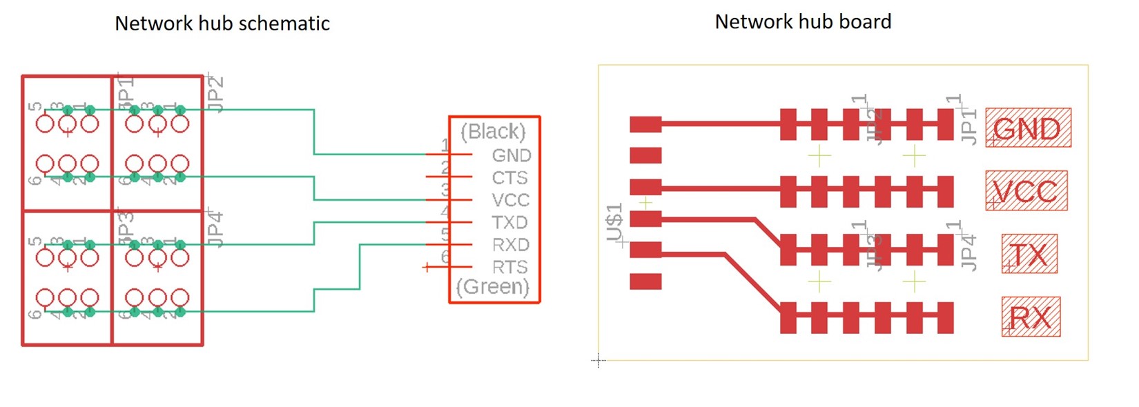
I am also planning to do networking through serial communication. I design a hub for serial communication board to make network my input and output devices.
See the network hub schematic designed for serial network communication.
Group assignment
Group members
Group assignment we work together, we randomly choose some board to make separate nodes. We tried to communicate with Bluetooth module to a different project developed in the previous week. We program each board selected as Jobin_Node1, Sahan_Node2, Mikel_ Node3 and Yasir_Node4. All the board we programmed and connected serially and control through Bluetooth applications. See the working of a wireless network for the multiple projects connected serially.
See the below figure which connected all separate project using serial bus and controlled wirelessly using Bluetooth module.
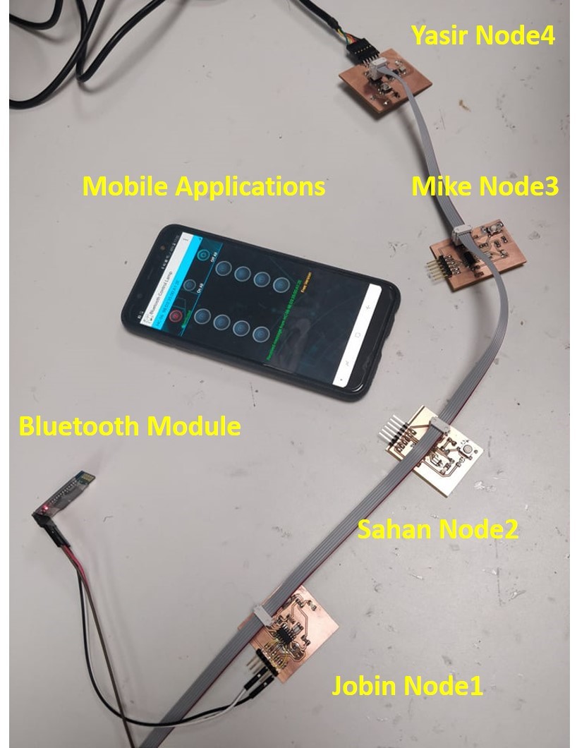
The details of working are presented in the below video, which explains how we can control multiple projects using wireless networking using Bluetooth module.