3. Computer Aided design
This weeks assignment was to model (raster, vector, 2D, 3D, render, animate, simulate, …) a possible final project, and post it on your class page.
Learning outcomes
- Evaluate and select 2D and 3D software
- Demonstrate and describe processes used in modelling with 2D and 3D software
2D
Raster (Bitmap) picture is Pixel-based link to the source. Raster programs are best for editing photos. Large dimensions & detailed images equal large file size. Raster images are the most common image format, including: jpg, gif, png, tif, bmp, psd, eps and pdfs. Common raster programs are photo editing / paint programs such as Photoshop & Paint Shop and GIMP.
Vector shapes are based on mathematical calculations. Vector programs best for creating logos, drawings and illustrations, technical drawings. Vector images can be scaled to any size without losing quality. They can be printed at any size/resolution. A large dimension vector graphic maintains a small file size. Vector art can be used for many processes and easily rasterized to be used for all processes. Vector images can be easily converted to raster. Common vector graphic file formats are ai, cdr, svg, and eps & pdfs. Common vector programs: drawing programs such as Illustrator, CorelDraw, Inkscape (free).
I am not very familiar with computer design programs. I have used Inkscape a little earlier in Fablab, but that was just by trying without knowing how it should be used. I decided to start my learning by installing Inkscape in my computer and finding some tutorials in Youtube by Derek Banas. These videos are very useful to learn the basics. I watched the video with one screen and did the same with another PC. I did the same with Adobe Illustrator (7 day trail version). I really recommend to do some guided work to learn to get started. Here are some pictures of my trials.
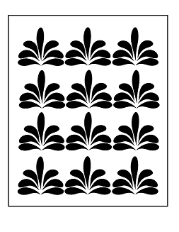
Illustrator trial learning how to use layers and how to create patterns:
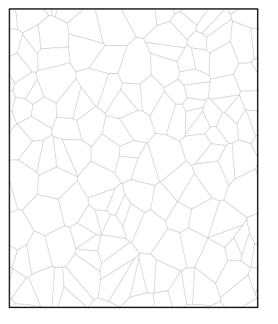
And here is a Vornoi pattern created with Inkscape:
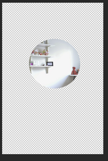
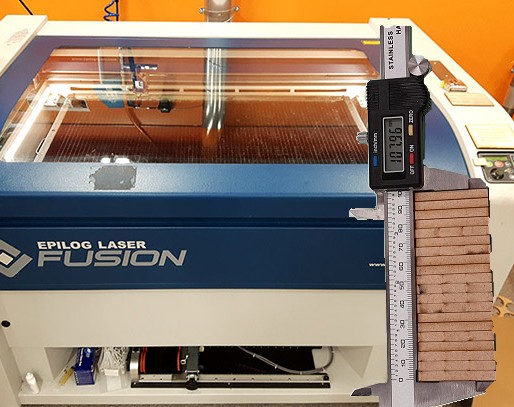
With GIMP I modified and combined two photos: I removed background from kerf-measuring image and added that on the top of laser-cutter image.
Next I started to sketch my final projet. I decided to use Inkscape. I had some idea in my mind about the pattern I want, but I needed to play around a bit with Inkscape to understand how to draw and what kind of operations could be used. I watched one tutorial about Bezier-lines and learned how to use those. This gave me idea how to use Besier-line tool in my lamp-design. Here are couple of first drafts for my lamp patters:
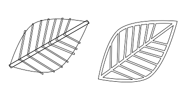
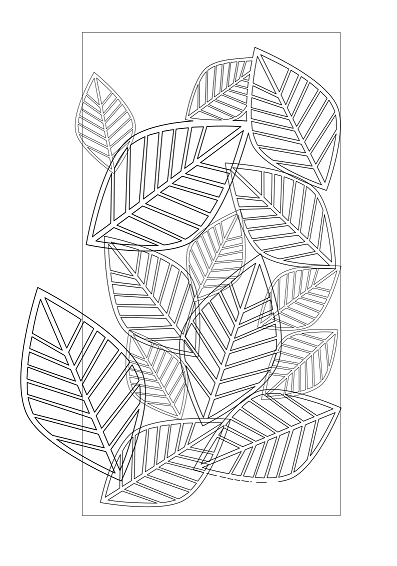
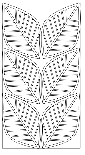
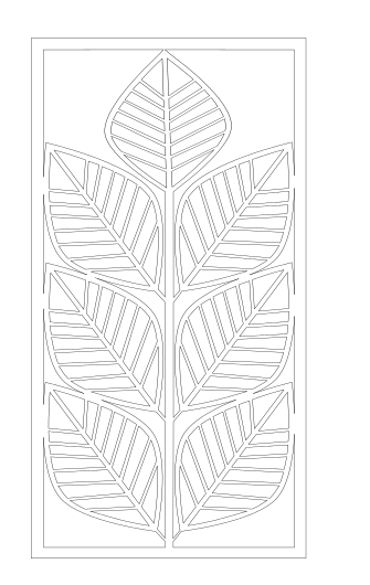
The leaf pattern actually looks very nice, next I needed to think how it should be constructed so that it can be laser-cut. I needed to learn how to combine patterns. I used the nodes-tool and learned how to add new nodes, and how to remove segments between nodes. Fo the entire leaf-pattern this took a lot of time, but finally it was ready to be called a first real version.
3D
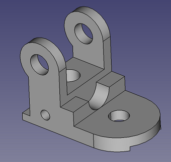
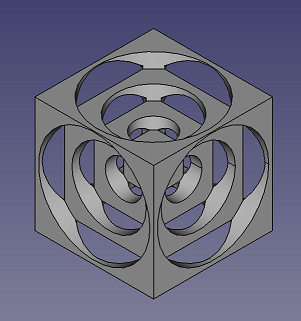
3D designing is completely new to me so I did the same thing that in 2D designing and started the learning with youtube videos and doing the examples myself at the same time. I started with FreeCAD and FreeCAD Lessons by Roland Frank. Again, I need to say that this practicing with tutorials is really needed to be able to learn the basics properly, at least for me.
My FreeCAD trials with guided tutorials:
I wanted to try also Fusion 360. After installing the program I watched some nice Youtube Fusion 360 Tutorials for Absolute Beginners by Lars Christensen.
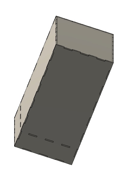
Next I wanted to try to create a 3D sketch of my Led-lamp. I started with a simple box and I extruded the sides open. Another try was to insert the SVG-file of my leaf pattern. This seemed somewhat challenging and I might need some help to get this really working.
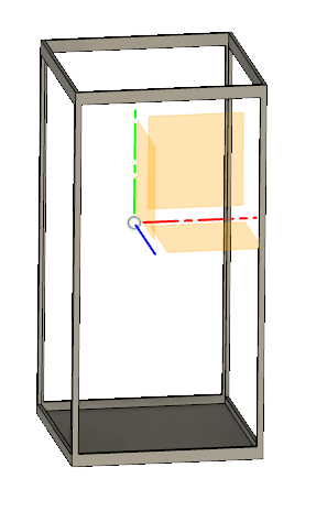
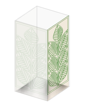
I decided to design the basic shapes for my lamp with Fusion 360. I don’t know yet if I will add the leaf pattern in parts in Fusion 360 or in Inkscape.
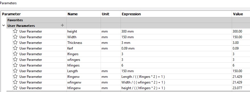
First I added design parameters
I drew one side panel. I draw a rectangular and extruded it to parameter “Thickness”. I added a slot for finger joints to one side by drawing a rectangular and extruding with cut to “-Thickness”.

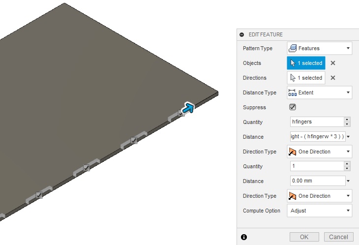
After that I created a pattern to add finger slots to the whole side
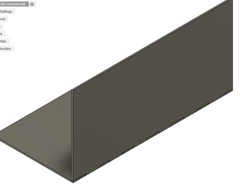
I used Mirror tool to add similar finger slots to the other side.
Then I drew next side panel and extruded it to “Thickness” parameter
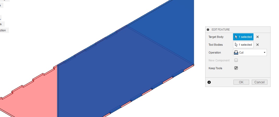
I used Combine tool to create matching fingers to the new side panel. New panel is the target body and the first panel with finger slots is the tool body.
Using the same procedure I added all side panels, bottom and top panels and intermediate level. In the space between this and bottom panel I will have the electronics of my lamp.
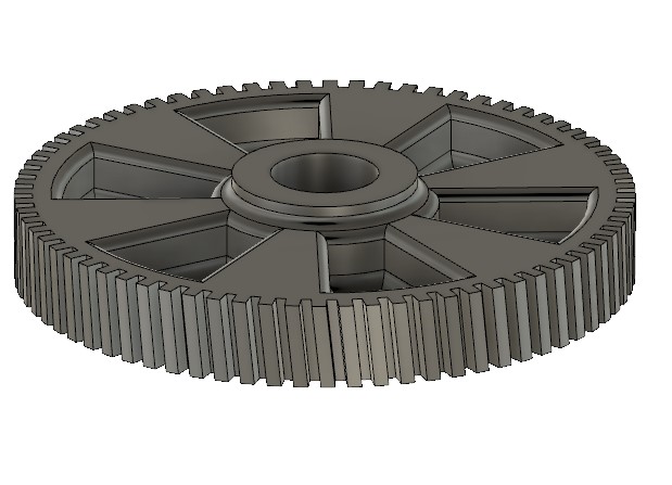
I also designed a gear with Fusion 360. This is a replacement piece for an old broken gear.
Files
Inkscape file Lamp
Inkscape file Vornoi
FreeCAD 1
FreeCAD 2
Lamp 3D shape Fusion f3d file
Lamp 3D shape Fusion stl file