11. Input devices
Group assignment
- probe an input device’s analog levels and digital signals
Individual assignment
- measure something: add a sensor to a microcontroller board
- that you have designed and read it
Group assignment
Group members: Lukasz, Gleb, Perttu, Jobin and I
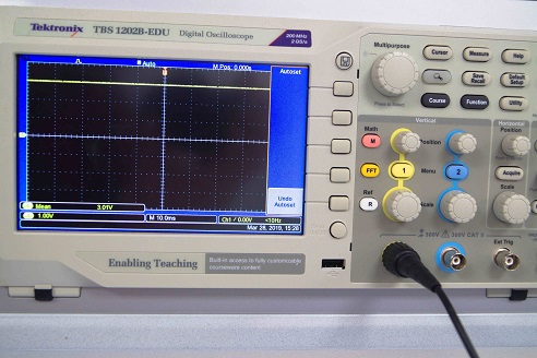
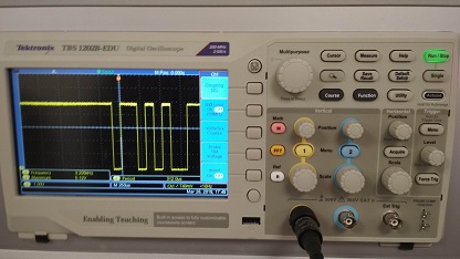
We decided to start with measuring signals from analog input devices using photovoltaic modules we found, they are like mini sized solar panels. We tried the differences between fluorescent lamp and Smartphone LED.
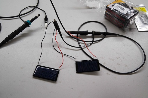
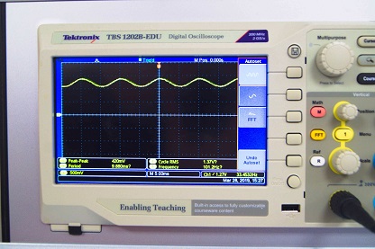
We connected our test units in series obtain higher voltage values. We used oscilloscope to measure output.
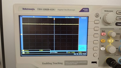
Differences are clearly visibly. LED provided stable voltage level, where lamp was flickering with 50 Hz frequency.
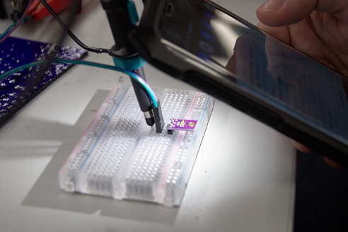
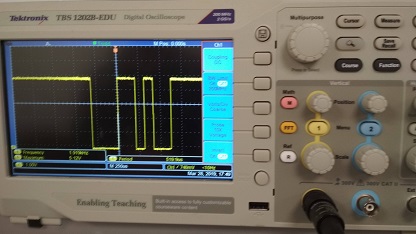
Next we decided to work with ATTiny. We had photoresistor, which changes its resistance in presence of light. Circuit was simple - voltage divider. Value of first resistor is fixed, where photoresistor resistance varies. Voltage across photoresistor will change depending on light strength. There are three pins, which needs to be connected. Power line (TTL logic values), ground and signal pin - output value.
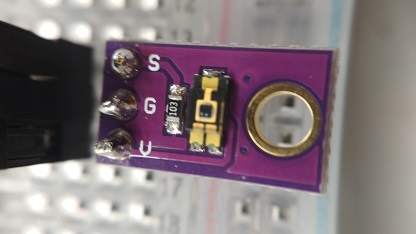
We checked the values using oscilloscope to make sure it works. Circuit was powered from USB port. Everything worked as expected.
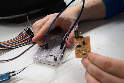
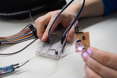
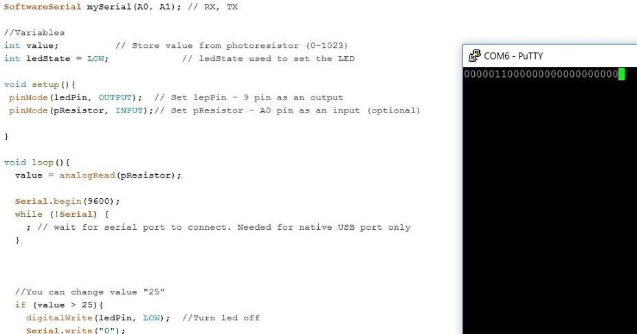
We created a code using Arduino IDE, which was turning LED on every time photoresistor was lacking light. Our previously designed board didn’t have pinheaders to connect with output boards, so we soldered signal line to unused port.
After programming circuit was supplied from USB port. It didn’t require more than two connections, 5V and GND. After couple attempts we managed to make it fully functional.
Finally, we decided to test analog to digital version. ATtiny will send some characters depending on what it will sense with previously used photoresistor.
We modified Arduino code so that every time there will be no light detected “0” will be send, where any voltage (create by light) above given threshold will send “1” over serial port. This would be easily readable using putty. After couple attempts we achieved it.
After a moment we decided to investigate Arduino function Serial. Wire and instead using characters, we used ASCII codes. We picked two random numbers: “43” and “44”. It turned out that first was plus sign and second was comma. We measured transmission using oscilloscope. Everything worked well.
Individual assignment
I decided to use this week to be part of my final project. I planned to design the slide button for dimming and brightening the led light of my lamp.
I did some research to have some ideas how to do the design. I found very nice example by Akash Badshah, originally Neil’s code example. The difference in my design is that I will take the sensors away from the PCB and have them attached in plywood in my lamp.
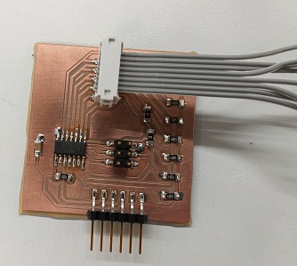
I did the design with Eagle
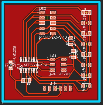
and I milled the board with Roland SRM-20, just like in week05 and week07. After that I soldered the components to board.
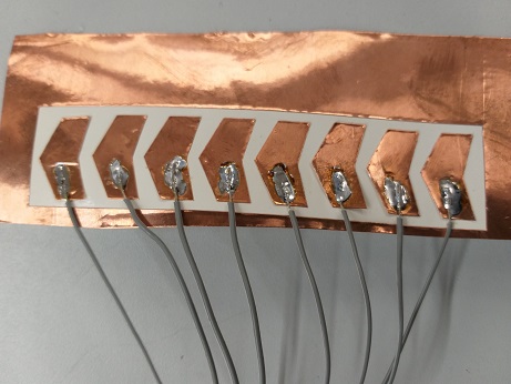
I cut eight sensors from copper sheet using vinyl cutter (see vinyl cutting procedure in week04 and soldered wires for them.
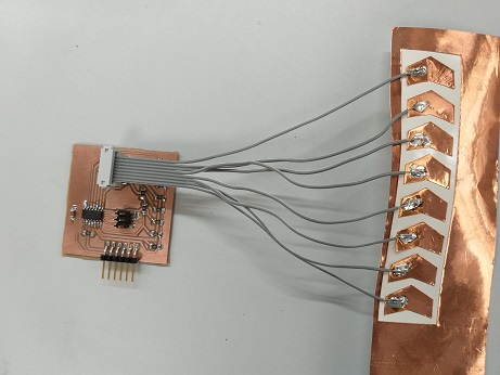
Sensors are connected to the board with wires
Next I programmed the board using the same procedure as on week09. I used the code from Akash Badshah with some modifications so that I will see how the sensors are working.
The code uses step response for the touch detection. The response of a pin, connected to a copper plate, is measured as a step response of a “charge” pin. Charge pin is connected to the copper plate through a high impedance resistor. check_pin() -function reads the analog input value after applying a step response in the charge pin. Then it transforms this value into digital using ADC conversion, see the detailed explanation in section 16 of the ATTiny 44 datasheet.
//Check an ADCPin identified by bitmask
int check_pin(unsigned char pin) {
unsigned char up_lo,up_hi,down_lo,down_hi;
int up_value, down_value, value;
//
// set the A/D pin
//
ADMUX = ref | pin;
//
// settle, charge, and wait 1
//
settle_delay();
set(charge_port, charge_pin);
charge_delay_1();
//
// initiate conversion
//
ADCSRA |= (1 << ADSC);
//
// wait for completion
//
while (ADCSRA & (1 << ADSC))
;
//
// save result
//
up_lo = ADCL;
up_hi = ADCH;
//
// settle, discharge, and wait 1
//
settle_delay();
clear(charge_port, charge_pin);
charge_delay_1();
//
// initiate conversion
//
ADCSRA |= (1 << ADSC);
//
// wait for completion
//
while (ADCSRA & (1 << ADSC))
;
//
// save result
//
down_lo = ADCL;
down_hi = ADCH;
//
// process result
//
up_value = 256 * up_hi + up_lo;
down_value = 256 * down_hi + down_lo;
value = (up_value + (1023 - down_value)) / 2;
return threshold - value <= 0 ? 0 : threshold - value;
}
I changed the threshold value to 50, to fit my sensor values. I also added a line to the code that will print the sensor values on the serial monitor so that I can check which sensor is touched and if the threshold value is ok.
print_int(measurements[i]);
In the main loop, these values are stored in measurements[] variables and all values (0-7) are printed with print_int() function.
I don’t have the led light control part ready yet, so I need to check the output in Serial Monitor of Arduino IDE. I am planning to design another board in Output week (next week) to have the lamp control ready. Together with this week’s sensor this will control the led lights of my final project.
I uploaded the code to the board with my programmer and Arduino IDE. After that I removed the programmer and connected the board to my laptop with FTDI cable. I opened the Serial Monitor in Arduino IDE to see if the sensors are reacting to the touch.
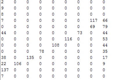
Serial monitor is showing 0 when sensor is not touched (expect sensor number 1, I don’t know at the moment why this is not zero like the others).
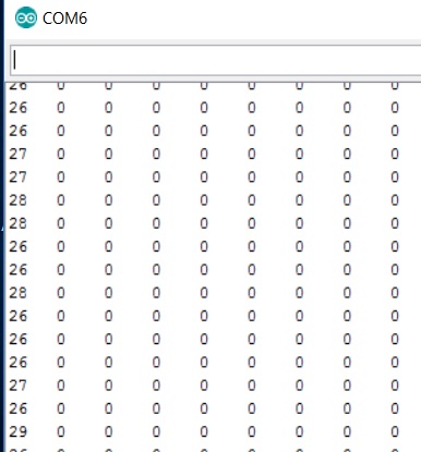
When touching the sensors one by one, the values are around 100 so it clearly shows that sensors are reacting to the touch.
After week12 I will combine the functionality of this week’s board and week12 board to make the full process for light control using touch sensors.
Reflections
I had to re-do the board milling couple of times, I was cutting too deep and I lost some traces. There was also some problem with the milling bit and the milling bed was uneven. You should be very careful when planning and starting the milling. Many issues are affecting to the result.
It was easy to make the copper pads for sensor with vinyl-cutter. I need to do another version for my lamp though, the glue behind the copper is not holding well to the paper and the glue sticks to unwanted places when testing the sensor. For the final version I will cut the copper pads just before attaching them to the final place in the lamp.
Files
Eagle board schematic
Eagle board png
Eagle board outline png
Board rml file
Outline rml file
Touch sensor code