4. Computer controlled cutting
In this week, I created different figures, cut and printed them using the vinyl cutter the and laser cutter.
For the group assignment, we used acrylic and MDF to measure the kerf made by the laser cutter. I learned about parametric design and how to take the kerf into consideration in design (still a bit confusing, but getting there).
Assignment
Group assignment:
- Characterise your laser cutter, making test part(s) that vary cutting settings and dimensions.
- For this task, our group included Alok Sethi, Arash Sattari, and me. We will be doing the future group tasks together.
Individual assignment:
- Cut something on the vinyl cutter
- Design, laser cut, and document a parametric press-fit construction kit, accounting for the laser cutter kerf, which can be assembled in multiple ways
Group Work
Measuring the kerf
Kerf is the width/thickness of a cut made by the cutting tool as it cuts through different material such as wood, cardboard, acrylic, etc. The material removed during cutting 1. It is important to know the kerf so that the pointer of the cutting process (laser, water jet, etc.) can be slightly offset to allow for it.
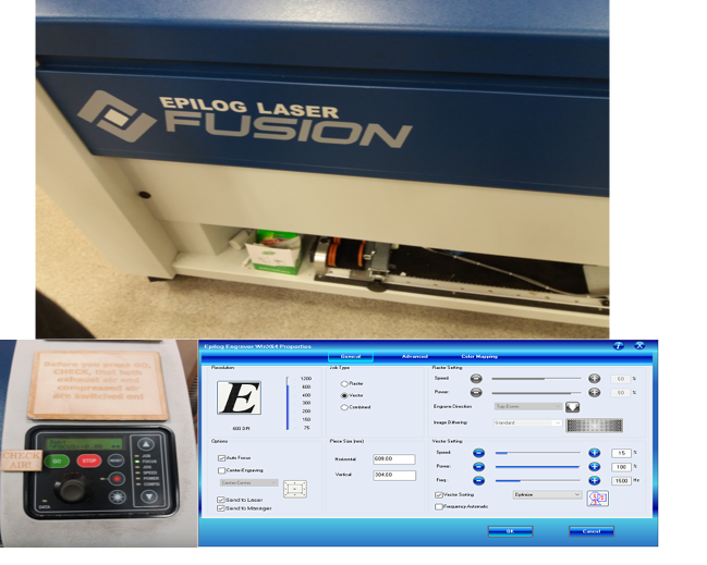
For this and the press-fit construction task, we used an Epilog Laser cutter and defined different settings for cutting. The image below shows the laser cutter, its control panel where you set the origin and position the cutter, and the different settings on the computer for defining the cutting parameters when sending a file.
The settings differ depending on whether one is:
- engraving (raster - created with pixel-based programs),
- cutting (vector - created with vector-based software that is focused on drawing shapes and their outline), or
- both (combined) (described below).
In the dialog box for printing under advanced settings, you can also choose the material for printing. These include cardboard, MDF, acrylic of different thickness which are defined in the program amongst others. The thickness should be defined when designing the file to be laser cut.
To make the test parts, we designed an image in Inkscape with eight slots of varying sizes that were equally positioned across a rectangular diagram. The width of each slot was 10 mm minus the number indicated on the base of the slot. Below are the laser cut images showing the dimensions used.
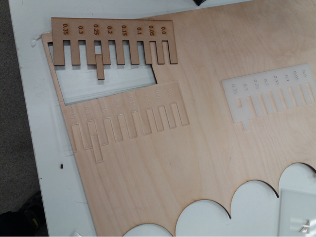
We had another rectangular piece 10 mm wide and this was used to measure the kerf. We tested this piece with the different slots to see in which one it fits. We considered half of the number below the slot as the kerf for the laser cutter machine for the type of material we used. The image below outlined the design method. The left image in the picture is the slots and the dotted lines indicate the laser beam path. The right diagram in the image is the test piece.
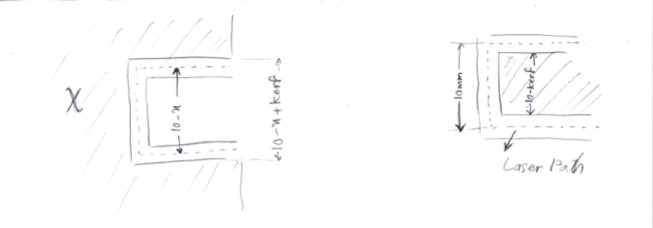
When the test piece fits into a particular slot, it means that the width of the test piece is equal to the width of the slot. The basic equation used to calculate the kerf is shown below:
10 - x - kerf = 10 - kerf
kerf = x/2
We did the test with 3 mm MDF material and 3 mm acrylic. The kerf for MDF was 0.125 mm and the kerf for acrylic was 0.175.
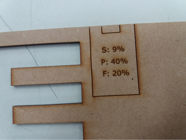
We also changed the settings of the laser cutter to see the effect on the material being cut. For cutting we changed the power (the power of the laser beam). We first tried 20% and then the 40% shown in the image below.
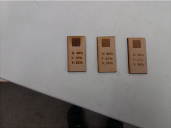
We also did the same for engraving where we changed the settings for speed (how fast the laser moves throughout the material) and power. For engraving, we noticed that when the speed is low and the power is high, there were burning traces produced around the engraved area. The best outcome was when the speed was high and the power was reduced as seen in the rectangle on the right with settings of 60% for speed, 30% for power and 50% for frequency in the image below. Frequency is always constant or at least we could not change it when we were trying different laser cutter settings.
NB: We were later told that for small engravings, the speed shouldn’t be more than 50%.
In the laser cutter’s control panel:
-
JOG is used to set the origin for starting the cutting and it is selected with the up and down arrows. A joystick is used to position the laser at the start point and when in position, press the joystick to set the Jog.
-
FOCUS sets the correct height of the table of the cutter. An 2-inch aluminium piece is used to set the height by using the joystick’s up and down motions to position the table. When in place, the aluminium is removed and the focus is set.
-
JOB is used to select the work to be cut from the printing queue. There might me multiple jobs sent to the laser cutter and it is important to do this before cutting to ensure that the right one is selected.The joystick is again used and when the right job is selected, an estimated cutting time will be displayed on the control panel.
After all the settings are done, press GO and the cutting will start.
Second Kerf Test
In the second test for measuring kerf, we cut 20 lines in the material and then measured the difference between the whole and the combined width of the removed pieces. Below is the image of the graphics generated in Inkscape. This yielded 19 free rectangles which were measured and then compared with the hole left. Kerf was defined as: (WH - ∑WPi )/20
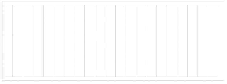
The measurements were done on the main laser on 2 materials (3 mm acrylic and MDF) and on the mini epilog laser on 3mm acrylic. For the smaller epilog laser, the frequency was varied. No settings beside the material profile, were changed on the big laser machine.
| Material | Kerf | Parameter/Description |
|---|---|---|
| 3mm Acrylic | 0.1215 | Big laser, default parameters |
| 3mm MDF | 0.1275 | Big laser, default parameters |
| 3mm Acrylic | 0.274 | Small laser, Frequency 1500 |
| 3mm Acrylic. | 0.2665 | Small laser, Frequency 500 |
| 3mm Acrylic | 0.225 | Small laser, Auto Frequency |
Making press-fit construction kit
For the press fit construction kit, I looked at past projects to get ideas. I would have liked to design one with multiple connection points, but as I am still getting to grips with Fusion 360, this initial exploration took longer than expected. Ultimately, I just decided to go with the simple design by last year’s Oulu Fab Academy student, Megumi.
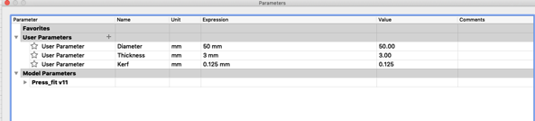
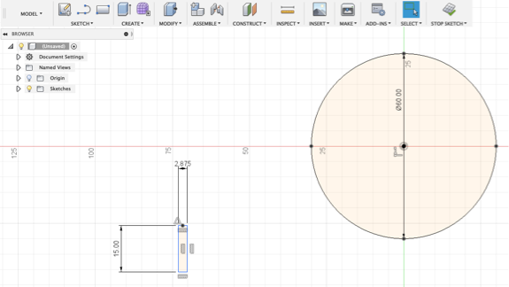
In Fusion 360, I first defined the parameters. I set the diameter to 60 mm, thickness to 3 mm, and the kerf to 0.125 mm. This was the kerf size we found in the first test we did with 3 mm MDF.
I drew a circle and put the diameter defined in the parameters. Next I drew a rectangle for a slot which was to be the connection point for the press-fit kit(s). The slot width was set as the difference between the material thickness and the kerf (thickness — kerf). I set the height of the slot as diameter divided by 4 (Diameter/4).
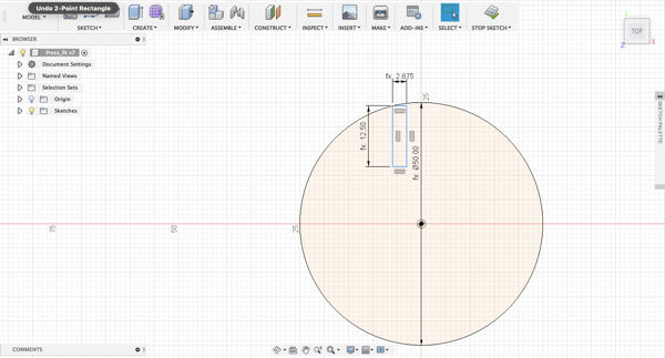
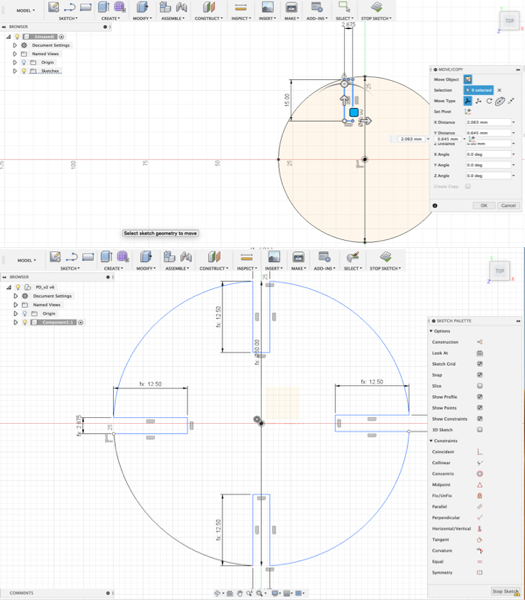
In order to prepare for replicating the rectangle along the four points of the circle, you select the image and in the Fusion 360 menu you click on SKETCH<Point. Then click on the centre point of the rectangle along its width and also along the fours points on the X and Y axis around the circle as shown in the image below.
To align the rectangle symmetrically along the centre points of the circle, you either copy and paste it or select MODIFY> Move/Copy from the Menu after selecting it. Options to position the rectangle appear. To snap the rectangle to the centre points of the circle that were earlier selected (in the image above), you click on the midpoint along the width that was selected with the Point tool. In the MOVE/COPY box that appears, you pick the fourth option – Point to Point – under Move Type (circled) and the rectangle will move to the centre point. Copy/Paste and position for the other three positions. You can use the first option (that is highlighted) under Move Type in the MOVE/COPY box to rotate the rectangle or any other object you would like to move.
When the rectangles are positioned, you trim (SKETCH>Trim or T on the keyboard) the points where they join the circle to create the openings. Then click on STOP SKETCH. From the tool bar, go to CREATE>Extrude or just the letter E from the keyboard, click on the circle and it will be highlighted. Extrude the rectangles by 3 mm and you end up with the following image.
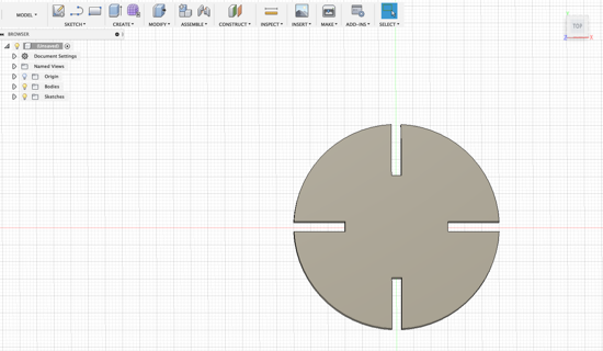
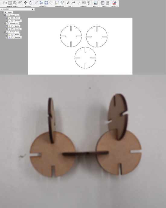
Then select MODEL>DRAWING>Drawing from design to prepare the file for printing. From the DRAWING VIEW box change orientation to Top, Style to Visible and Hidden Edges and Scale to 1:1 and click ok. Duplicate the object a few times by selecting DRAWING VIEWS>Base Drawing and repeat the process in the preceding sentence. Now the image is ready for cutting. I saved it as a pdf and opened in the computer with the software for operating the laser cutter. I used the laser cutter settings outlined in Measuring the kerf and the result is shown below.
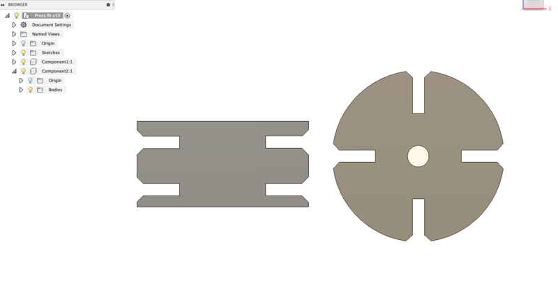
I modified the previous design by adding a hole in the middle and chamfer in the slots of the circle. I also added a rectangle with 4 chamfered slots and used similar parameters for diameter, slot height and width as those for the circle.
Below are the parameters for the edited press-fit.
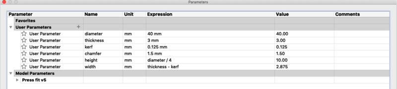
The modified press-fit design.
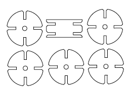
I copied and pasted the circle a few times resulting in the following image to be laser cut.
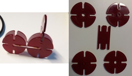
And the final result.
Using the Vinyl Cutter
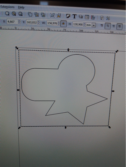
I designed a simple image in Inkscape that was a combination of three shapes. From Inkscape’s toolbox, I selected a rectangle, circle, and star. I then placed the circle on the top of one side of the rectangle, the star shape on the bottom of the same side, in Fill and Stroke box, I chose no Fill, Stroke Paint and a Width of 0.05 mm under Stroke Style. I also drew a rectangle around the image so that it would be easier to remove the cut image from the bigger sheet placed in the cutter. Then clicked on Path from menu and selected Union (alternatively, from the keyboard C++) and the result is as presented below. A new path is created containing all the shapes.
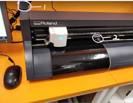
The Vinyl cutter in our Lab is a Roland GS24. I placed a sheet on the machine, pulled the lever (1 in the image below) to hold the sheet in place and positioned the rollers which should be aligned on the grit marks (2 in the image below) to set the cutting area.
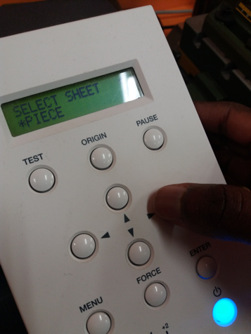
From the Vinyl Cutter’s control panel, I selected sheet as Piece with the arrows and set the origin. The size the of the piece (the design to be cut) is measured and displayed on the screen. The other options for cutting are Roll (where the machine assumes there is a big enough sheet) and Edge (cutting will start from the edge of the sheet. This measures the width of the sheet and you have to measure the height of the design and insert this measurement when printing it).
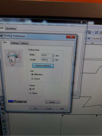
From the computer, open the design select print, printing preferences, and in Cutting Area, click on Get from Machine to get the right dimensions that were set from the machine’s control panel. Increase the length’s dimension by 10 to 20 mm so that the cutter leaves a gap between the edge and the design. Measurements for the width are not changed. Then print.
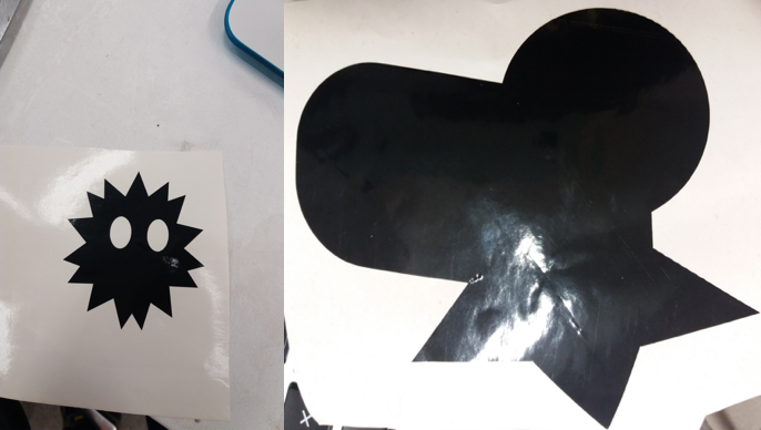
The result can be seen below after removing the cutout from the bigger sheet of paper. For this simple design, removing the cut part was easy as there weren’t any small curves or areas. I simply pulled out the vinyl cut area after from the edges by hand. For more complicated designs with smaller or closely connected lines, a tweezer is needed. I also made another simple design using the same process by combining multiple star shapes and adding the two eyes.
Resources used
- Inkscape
- Autodesk Fusion 360
- Roland GS24 Vinyl Cutter
- Epilog Fusion Laser Cutter
Original Files
Click on the links to download the design files:
Reflection
The tasks for this week took longer than I would have liked them to. First, I started doing the press-fit kit in Inkscape and I was missing a small step in the process, so could not complete it. Second, it took me a while to understand parametric design and what a kerf is. After getting stuck on the small step in Inkscape (it was an issue with cloning and merging cut out parts), I decided to do a simple press-fit kit in Fusion 360 following an example from the previous year. The steps outlined above were the longer way around it as I could have used the clone/mirroring tool to simplify the process of creating the slots in the circle. An advantage is that I got more familiar with Fusion and the different commands.
When Vinyl cutting, placement is important as the sheet may not be cut well if it is not completely flat on the cutter’s surface. Also, text should be in big fonts and well-spaced (or better yet, just avoid text) as I felt it was a hustle removing the inner and surrounding pieces of the sheet.