9.Embedded Programming
Individual assignment
Read a microcontroller data sheet.
As of lately, I have been reading the ESP32 datasheet for my final project.
For this week read the “8-Bit Microcontroller with 2K/4K/8K Bytes In-System Programmable Flash, ATtiny24A, ATtiny44A, ATtiny84A”datasheet.
Reading this datasheet will be advantageous for my future projects which include:
* The idea for making an animated 8-bit sprite student overall iron on patch. Some neopixels and ATtiny for controlling should make some overall patch.
* Idea for PWM controlled digitally monitored power supply for energy-efficient power controlling for future projects.
Surprisingly the ESP32 datasheet takes granted many things that the ATTiny datasheet explains in detail. Reading the ATTiny datasheet helped a lot understanding the datasheet of the ESP32.
The ATtiny24A/ATtiny44A/ATtiny84A features:
• High Performance, Low Power AVR® 8-bit Microcontroller
• Advanced RISC Architecture
RISC - Reduced instruction set computer is is instruction set architecture (ISA) allows it to have fewer cycles per instruction, this makes a faster compilation if commands. The many varieties of RISC designs include ARC, Alpha, Am29000, ARM, Atmel AVR, Blackfin, i860, i960, M88000, MIPS, PA-RISC, Power ISA, PowerPC, RISC-V, SuperH, and SPARC. And many others.
– 120 Powerful Instructions – Most Single Clock Cycle Execution
Native instructions are faster and more effective. The full list of instructions can be found from the Atmel AVR instruction set
– 32 x 8-bit General Purpose Working Registers
All arithmetic and logic operations operate on these registers.
– Fully Static Operation
ARV microprosessors can run at 0 Hz.Static stasis. Some older processors needed a minimum clock to keep it alive. Saves energy because onboard clocks are not needed to keep on.
High Endurance, Non-volatile Memory Segments
– 2K/4K/8K Bytes of In-System, Self-programmable Flash Program Memory
• Endurance: 10,000 Write/Erase Cycles
The microcontroller can write to its own program memory when
running code from the boot sector. This creates new possibilities for the designers using self-programming memory-based microcontrollers.
– 128/256/512 Bytes of In-System Programmable EEPROM
• Endurance: 100,000 Write/Erase Cycles
Electrically Erasable Programmable Read-Only Memory. A type of Flash memory.
– 128/256/512 Bytes of Internal SRAM
– Data Retention: 20 years at 85°C / 100 years at 25°C
– Programming Lock for Self-programming Flash & EEPROM Data Security
Static random-access memory. Volatile on hold type of memory.
• Peripheral Features:
– One 8-bit and One 16-bit Timer/Counter with Two PWM Channels, Each timer can be individially controlled
Timer0 controls the main clocks of the Attiny. The timer1 is 16-bit timer. From these timers, multiple functions that needs a clock to function are generated.
– 10-bit ADC
• 8 Single-ended Channels
• 12 Differential ADC Channel Pairs with Programmable Gain (1x / 20x)
Analog to Digital Converter. ADC can read analogical signal varying in voltage. The maximum voltage can be set with reference voltage to Vcc, external, or internal reference.
differential ADC channel gives the difference of two analog
– On-chip Analog Comparator
The comparator is used to compare a changing voltage with a fixed reference voltage.
– Programmable Watchdog Timer with Separate On-chip Oscillator.
Timer to check if the running program is crashed or not.
– Universal Serial Interface
The Universal Serial Interface (USI) is a multi-purpose hardware resource which provide the basics hardware for various serial communications and is faster and reliable then implementing it in software.
The USI can be used in Two wire mode and in three wire mode:
• 2 wire mode –> I2C/TWI
• 3 wire mode –> SPI
• Special Microcontroller Features:
– debugWIRE On-chip Debug System
The debugWIRE interface was developed by Atmel for use on low pin-count devices. Unlike the JTAG interface which uses 4 pins, debugWIRE makes use of just a single pin (RESET) for bi-directional half-duplex asynchronous communication with the debugger tool.
– In-System Programmable via SPI Port
In-system programming (ISP), also called in-circuit serial programming (ICSP), is the ability of some programmable logic devices, microcontrollers, and other embedded devices to be programmed while installed in a complete system, rather than requiring the chip to be programmed prior to installing it into the system.
– Internal and External Interrupt Sources
• Pin Change Interrupt on 12 Pins
In system programming, an interrupt is a signal to the processor emitted by hardware or software indicating an event that needs immediate attention. Multiple external pins can act as the source of the interrupt. Internal interrupts can be programmed.
– Low Power Idle, ADC Noise Reduction, Standby and Power-down Modes
Good power handling.
– Enhanced Power-on Reset Circuit
Power-on reset (POR) is required to initialize electronic systems or integrated circuits (ICs) when they are turned on. The POR signal holds target circuits in the reset state until the power supply voltage reaches a steady-state level at which the target circuits can operate correctly.
– Programmable Brown-out Detection Circuit with Software Disable Function
Brown-out Detection (BOD) circuit for monitoring the Operating Voltage (VCC) level during operation. By comparing the VCC to a fixed trigger level it can determine if the device needs to be put into reset mode to prevent erratic operation.
– Internal Calibrated Oscillator
The microcontroller can be used without external oscillator of crystal up to 8Mhz clock speeds. This makes simpler board designs.
– On-chip Temperature Sensor:
• Industrial Temperature Range: -40°C to +85°C
The temperature measurement is based on an on-chip temperature sensor that is coupled to a single ended ADC8 channel. Selecting the ADC8 channel by writing the MUX[5:0] bits in ADMUX register to “100010” enables the temperature sensor.
– Twelve Programmable I/O Lines
Multiple pins for connection. Each pin can be programmed to do multiple things.
• Operating Voltage:
– 1.8 – 5.5V
Wide range of working voltages. Can be used in different environments.
• Speed Grade:
– 0 – 4 MHz @ 1.8 – 5.5V
– 0 – 10 MHz @ 2.7 – 5.5V
– 0 – 20 MHz @ 4.5 – 5.5V
Different operation speeds need a variation of operation voltage.
• Low Power Consumption:
– Active Mode:
• 210 µA at 1.8V and 1 MHz
– Idle Mode:
• 33 µA at 1.8V and 1 MHz
– Power-down Mode:
• 0.1 µA at 1.8V and 25°C
Good for low power applications like battery power devices.
The full datasheet describes the features and capabilities of the Attiny24/44/84. And gives full specifications of the operational registers of the Attiny their names, values and usage.
Programming the board.
The tested board was the one produced in the week 7
The Programming was done in Ubuntu 18.04. On the Linus ARVdude was installed using the “sudo apt-get install flex byacc bison gcc libusb-dev avrdude” command. In the week 7 The hello.ftdi.44.echo.c was programmed to the board using the programming board, FABTinyISP that was manufactured in week5.
Code
I have used Arduino IDE and Arduino coding language extensively. I have made multiple lamps, party lights, electronic locks, motion sensors, noise sensors,Vetinari’s clock, etc. with Arduino and Arduino coding language.
I would like to learn C coding language. So I will be using that for this project. Also in the future I would like to learn the direct bit shifting of the registers.
The code consists of two files. First is the .make file. The make file determines the file for the c code, the used microcontroller type, the frequency of the CPU and other project parameters. Example of the .make file
    PROJECT=blink   // indicates the name of the c file
    SOURCES=$(PROJECT).c    //assign the c file name to a c file
    MMCU=attiny44           // determine the type of the CPU
    F_CPU = 20000000        // speed of the CPU clock

    CFLAGS=-mmcu=$(MMCU) -Wall -Os -DF_CPU=$(F_CPU)

    $(PROJECT).hex: $(PROJECT).out
        avr-objcopy -O ihex $(PROJECT).out $(PROJECT).c.hex;\
        avr-size --mcu=$(MMCU) --format=avr $(PROJECT).out

    $(PROJECT).out: $(SOURCES)
        avr-gcc $(CFLAGS) -I./ -o $(PROJECT).out $(SOURCES)

    program-bsd: $(PROJECT).hex
        avrdude -p t44 -c bsd -U flash:w:$(PROJECT).c.hex

    program-dasa: $(PROJECT).hex
        avrdude -p t44 -P /dev/ttyUSB0 -c dasa -U flash:w:$(PROJECT).c.hex

    program-avrisp2: $(PROJECT).hex
        avrdude -p t44 -P usb -c avrisp2 -U flash:w:$(PROJECT).c.hex

    program-avrisp2-fuses: $(PROJECT).hex
        avrdude -p t44 -P usb -c avrisp2 -U lfuse:w:0x5E:m

    program-usbtiny: $(PROJECT).hex
        avrdude -p t44 -P usb -c usbtiny -U flash:w:$(PROJECT).c.hex

    program-usbtiny-fuses: $(PROJECT).hex
        avrdude -p t44 -P usb -c usbtiny -U lfuse:w:0x5E:m

    program-dragon: $(PROJECT).hex
        avrdude -p t44 -P usb -c dragon_isp -U flash:w:$(PROJECT).c.hex

    program-ice: $(PROJECT).hex
        avrdude -p t44 -P usb -c atmelice_isp -U flash:w:$(PROJECT).c.hex
The second file is the .c file that has the code itself.
I make four different programs for the board:
- Blink. Makes the LED blink.
    #ifndef F_CPU
    #define F_CPU 20000000UL // 20 MHz clock speed
    #endif


    #include <avr/io.h> //Library to handle avr inputs and outputs
    #include <util/delay.h> // Library to add delays. Necessary for blinking.


    int main(void)
    {
        DDRB = DDRB | (1 << PB2);      // DDRB Port B Data Direction Register. Selects direction of pins
                                       // In this case PB2 is an output


        while (1)
        {
            //Set PB2 output to 1
            PORTB = PORTB | (1<<PB2);
            //Wait for 1000ms
            _delay_ms(100);

            //Set PB2 ouput to 0
            PORTB = PORTB & ~(1<<PB2);

            //Wait for 1000ms
            _delay_ms(100);

        }
        }
2.Button. When the button is pressed the LED lights up.
      #ifndef F_CPU
    #define F_CPU 20000000UL // 20 MHz clock speed
    #endif


    #include <avr/io.h> //Library to handle avr inputs and outputs
    #include <util/delay.h> // Library to add delays. Necessary for blinking.


    int main(void)
    {
        DDRB = DDRB | (1 << PB2);      // DDRB Port B Data Direction Register. Selects direction of pins
                                       // In this case PB2 is an ouptut
        DDRA = DDRA & ~(1 << PA7);      //Set PA7 as input


        while (1)
        {

            //Check if button is pressed (its value is 0 because the button has a PULL-UP resistor)
            uint8_t val = PINA & (1 << PA7);
            if(!val){
            //Turn the LED on
                PORTB = PORTB | (1<<PB2);
            }
            else {
            //Turn the LED off
                PORTB = PORTB & ~(1<<PB2);
            }


        }
    }
3.Blink button. When the button is pressed the LED blinks.
      #ifndef F_CPU
    #define F_CPU 20000000UL // 20 MHz clock speed
    #endif


    #include <avr/io.h> //Library to handle avr inputs and outputs
    #include <util/delay.h> // Library to add delays. Necessary for blinking.


    int main(void)
    {
        DDRB = DDRB | (1 << PB2);      // DDRB Port B Data Direction Register. Selects direction of pins
                                       // In this case PB2 is an ouptut
        DDRA = DDRA & ~(1 << PA7);      //Set PA7 as input


        while (1)
        {

            //Check if button is pressed (its value is 0 because the button has a PULL-UP resistor)
            uint8_t val = PINA & (1 << PA7);
            if(!val){
            //Set PB2 output to 1
            PORTB = PORTB | (1<<PB2);
            //Wait for 1000ms
            _delay_ms(100);

            //Set PB2 ouput to 0
            PORTB = PORTB & ~(1<<PB2);

            //Wait for 1000ms
            _delay_ms(100);


            }
            else {
            //Turn the LED off
                PORTB = PORTB & ~(1<<PB2);

            }


        }
        }
4.Blink fade. When the button is pressed the LED changes its brightness by fading. This is done in software PWM.
    #ifndef F_CPU
    #define F_CPU 20000000UL // 20 MHz clock speed
    #endif


    #include <avr/io.h> //Library to handle avr inputs and outputs
    #include <util/delay.h> // Library to add delays. Necessary for blinking.


    int main(void)
    {
        DDRB = DDRB | (1 << PB2);                  // DDRB Port B Data Direction Register. Selects direction of pins
                                       // In this case PB2 is an ouptut
        DDRA = DDRA & ~(1 << PA7);              //Set PA7 as input
       uint8_t fade_out = 0;            // stores the current fade value.
       #define BIAS_MAX 600
       #define BIAS_MIN 1                //limits of the fadevalue
        uint16_t bias = BIAS_MIN;

        while (1)                     // waits for button
        {


            uint8_t val = PINA & (1 << PA7);
            if(!val){             //Check if button is pressed (its value is 0 because the button has a PULL-UP resistor)

            //Set PB2 output to 1
            PORTB = PORTB | (1<<PB2);        // Set the LED port bit to "1" - LED will be turned on.

            _delay_loop_2(bias);        // Wait a little. The delay function simply does N-number of "empty" loops.

            PORTB = PORTB & ~(1<<PB2);        // Set the LED port bit to "0" - LED will be turned off.

            _delay_loop_2(BIAS_MAX - bias);     // Wait a little.
            if (fade_out == 0) {
          bias++;
          if (bias >= BIAS_MAX - 1) fade_out = 1;  //
        }
        else {
          bias--;                    // This everything changes the wait times between on and off state
          if (bias <= BIAS_MIN) fade_out = 0;    // changes the wait time chage direction on upper and lower bound.
        }


            }
            else {
            //Turn the LED off
                PORTB = PORTB & ~(1<<PB2);

            }


        }
    }
The blink code is based on the Tinysaur.org Blink example code
The fade code is based on the Tinysaur.org LED Fade example code
The button code is made by trial and error with every example from the internet forums about ATiny44 buttons.
Uploading the code.
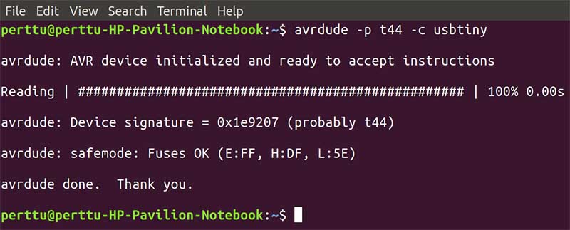
From the arvdude tutorial I looked up most useful commands. First I checked that the device is still working after two weeks in storage and was correctly initialized and fetch its signature. In the avrdude specify the PCB microcontroller (t44) and the programmer (usbtiny). And the avr dude recognizes the board correctly.
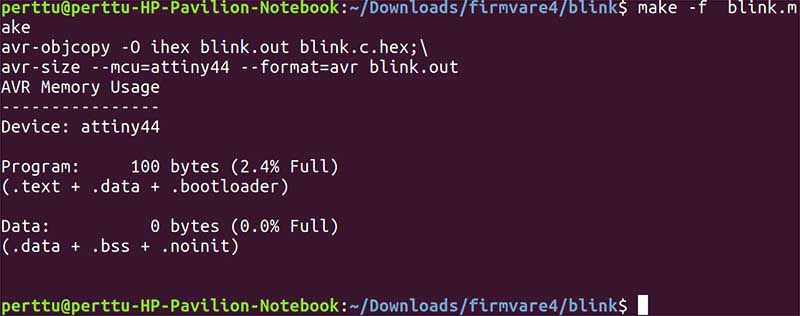
The code was then compiled by entering the command make -f blink.make This makes the necessary compiling of the files.
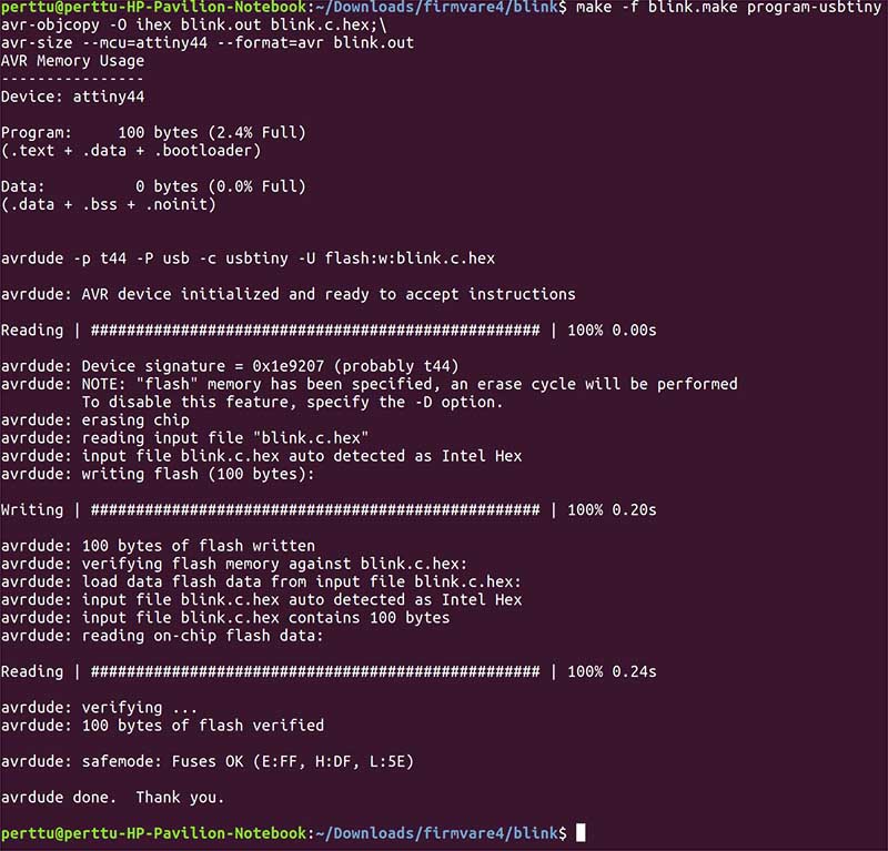
Then the microcontroller is flashed by entering the command
make -f blink.make program-usbtiny
After flashing the microcontroller the led starts to blink.
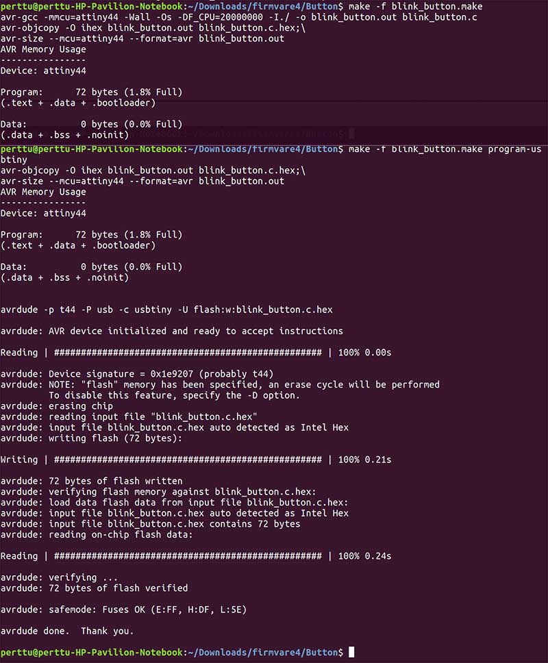
For the rest programs the flashin method was exactly same.
* First make -f .make
* Second make - f .make program-usbtiny.
The rest of the program visualizations are omitted because of the data size limits on the gitlab server. The functionality of the LED becomes clear on the first MP4. and the button functionality and the LED fade functionality in the second MP4. These two videos covers all the functionality of the code.
Group assignment
This week we worked all together as a one big group on the group assignment.
“compare the performance and development workflows for other architectures” This was interpreted as: ”
Test and use other architecture microcontrollers. As of some other architecture that Atmel architecture.”
Thus the Arduino IDE was used to programming. The appropriate libraries and toolchains were first imported to Arduino IDE. different IDE:s were not used.
Two different michrochip developer boards were tested:
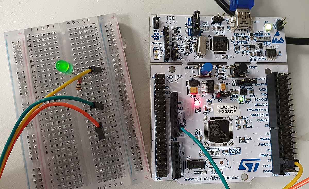
We tested the STM32 Nucleo-64 development board with STM32F401RE MCU and ESP32 LOLIN32 development board using Arduino IDE. ST32 is a family of 32-bit microcontroller integrated circuits by STMicroelectronics. This group is related to same 32 bit ARM processor. The STM32 F4-series is the first group of STM32 microcontrollers based on the ARM Cortex-M4F core. The F4-series is also the first STM32 series to have DSP and floating point instructions. The F4 is pin-to-pin compatible with the STM32 F2-series and adds higher clock speed, 64 KB CCM static RAM, full duplex, improved real-time clock, and faster ADCs. All devices offer one 12-bit ADC, a low-power RTC, six general-purpose 16-bit timers including one PWM timer for motor control, two general-purpose 32-bit timers. They also feature standard and advanced communication interfaces.
- Up to three I2Cs
- Up to four SPIs
- Two full duplex I2Ss. To achieve audio class accuracy, the I2S peripherals can be clocked via a dedicated internal audio PLL or via an external clock to allow synchronization.
- Three USARTs
- SDIO interface
- USB 2.0 OTG full speed interface See the data sheet STM32F401x for more information.
ESP32 is a series of low-cost, low-power system-on-a-chip microcontrollers with integrated Wi-Fi and dual-mode Bluetooth. The ESP32 series employs a Tensilica Xtensa LX6 microprocessor in both dual-core and single-core variations and includes in-built antenna switches, RF balun, power amplifier, low-noise receive amplifier, filters, and power-management modules. ESP32 is created and developed by Espressif Systems, a Shanghai-based Chinese company, and is manufactured by TSMC using their 40 nm process. See more details about ESP32 LOLIN32 in the link.
The SMT32 board manager can be installed to Arduino IDE by searching STM in the Arduino IDE Board manager menu and installing the Arduino STM32F4 Boards.
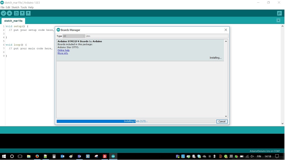
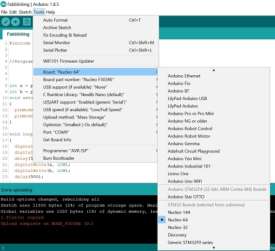
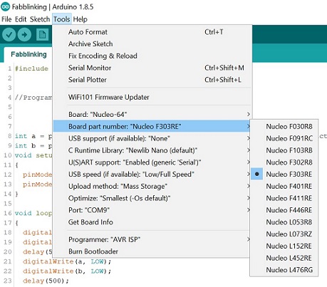
After the installation of the right board, Nucleo-64, is selected from the menu.
.
After finding what pin is attached to the on board LED the Blink example was modified to work on the board. External led was also attached to the board to blink at the same time.
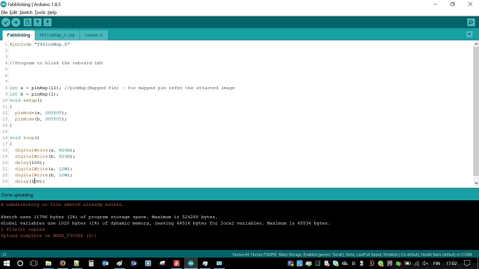
Code for the STM32 Blink:
  # include "f401Map.h"

  //Program to blink the onboard LED

  int a = pinMAp(12); //pinMap(mapped pin) - form mapped pin refer the attached image.
  int b ) pinMap(1)

  void setup{}
  {
  pinMode(a, OUTPUT);
  pinMode(b, OUTPUT);
  }

    void loop()
    {
    digitalWrite(a, HIGH);
    digitalWrite(b, HIGH);
    delay(100);
    digitalWrite(a, LOW);
    digitalWrite(b, LOW);
}
Video of the blinkin LEDs.
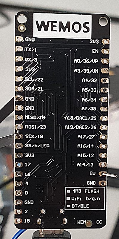
The process to install ESP32 libary is the same. Install board information from board manager, select board to match the used board and modify the output pind to correct ones. In this example, we used a strip of WS2812 LEDs to make the blink. The pinholes in the Wemos Lolin32 ESP32 can be used straight with the jumper cables for this demo.
Fastled Example code modified to the ESP32.
        #include <FastLED.h>

        // How many leds in your strip?
        #define NUM_LEDS 60

        // For led chips like Neopixels, which have a data line, ground, and power, you just
        // need to define DATA_PIN.  For led chipsets that are SPI based (four wires - data, clock,
        // ground, and power), like the LPD8806 define both DATA_PIN and CLOCK_PIN
        #define DATA_PIN 18


        // Define the array of leds
        CRGB leds[NUM_LEDS];

        void setup() {

               FastLED.addLeds<WS2812, DATA_PIN, RGB>(leds, NUM_LEDS);

        }

        void loop() {
          // Turn the LED on, then pause
          leds[0] = CRGB::Red;
          FastLED.show();
          delay(500);
          // Now turn the LED off, then pause
          leds[0] = CRGB::Black;
          FastLED.show();
          delay(500);
        }
This will blink the first 60 leds red in half second internal.
The pinout of the Wemos Lolin32 ESP32
Reflection.¶¶
The straight coding to Attiny is surprisingly easy after some time spend to get used to the datasheet logic and implemented terms and language.
The ready libraries of the ready boars in Arduino IDE makes the board environment swapping really easy.
Next step is to learn the Bit shifting and bit banging to make the Attiny programs more efficient.
All my code can be found at gitlab repository.