FINAL PROJECT
Initial Idea
The main idea for the final project was to design a Signal transmiting and recieving antenna system model which can rotate its transmistter and reciever antenns and to get diefferent measurements according to the requirement .
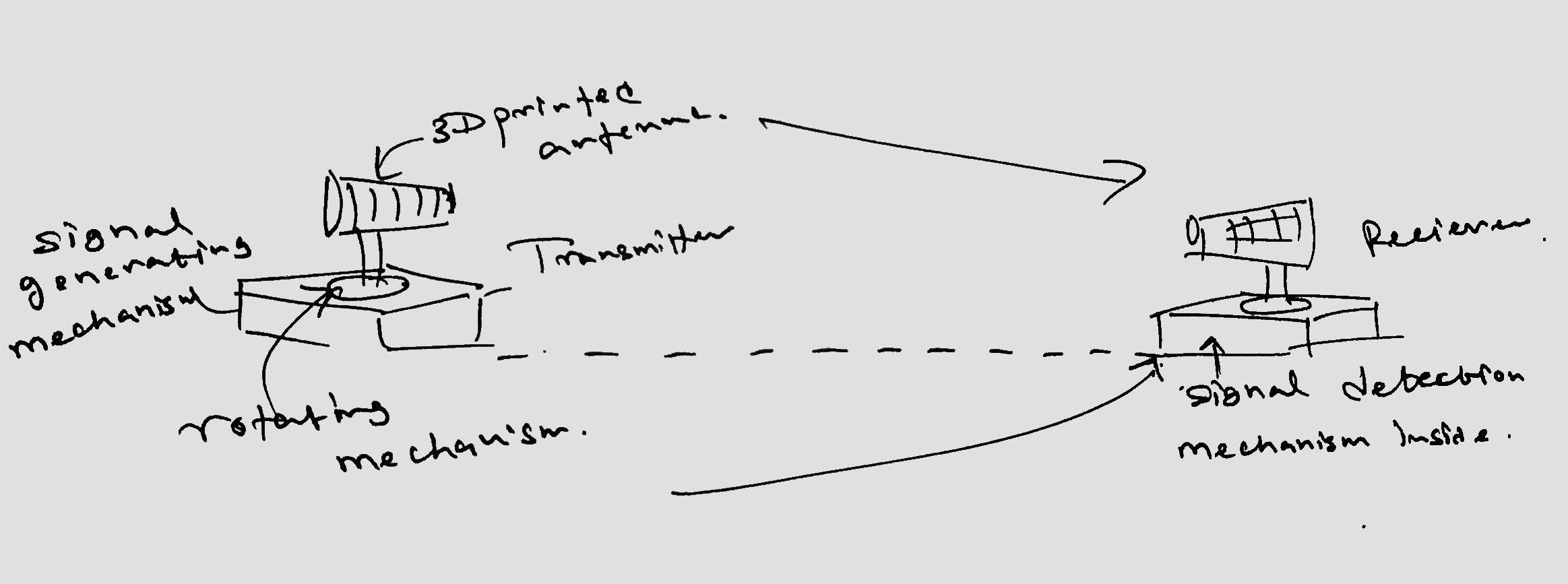
I thought this project will be helpful to measure the performance of different antennas. Moreover, I would try to make the design such that the transmitter and receiver are synchronized it will be controlled manually from a controlled panel.
To begin with, I started to search for searching for different types of antennas which can be smaller and easily mount. Then I found out that helical antennas have all these features which are useful in my design. It is simple in design and can be used for broadband applications due to wider bandwidth. Moreover, It offers higher directivity and it is very robust in construction.
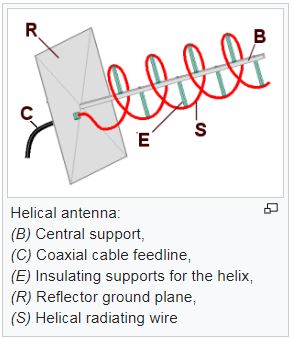
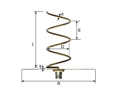
5.8 GHz frequency band was is selected for the design because the antenna is small enough for the design purpose and it is a one frequency band used in RC antennas. Therefore it has a wide range of applications. To do the calculations of the antenna I have used this website. The list of equations I found from few texts book s for antennas confirmed the measurements got from the website.
Then for the assignment of the computer-aided design I decided to model an antenna of the calculated dimensions. A more detailed version of design procedure can be found out in the week-3 page. The following 3-D figure shows the design I have made for the antenna.
What does it do?
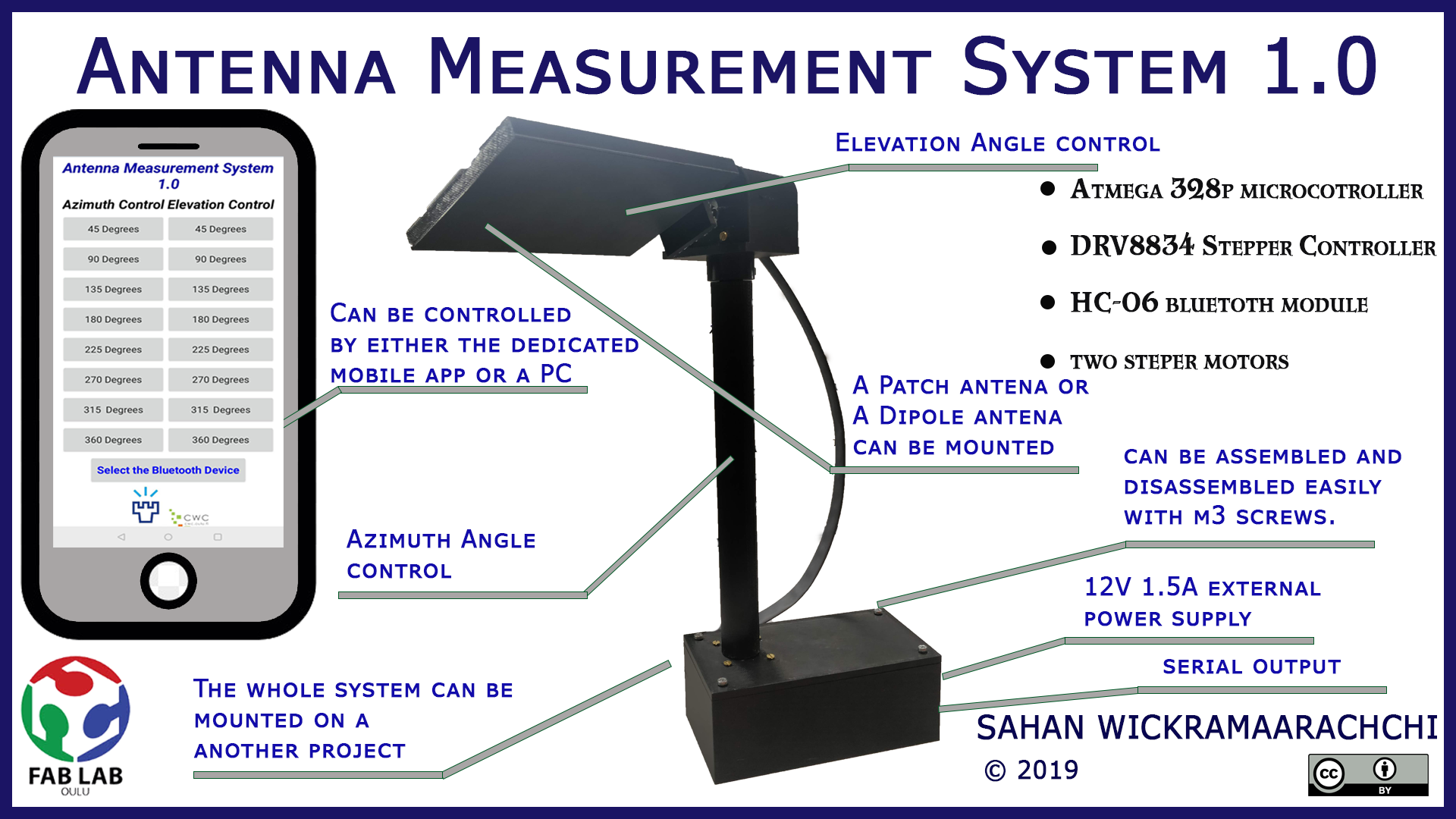
For my final project, I'm planning to make an antenna measurement system which can measure the radiation pattern of an antenna according to different angles of measurements.
who has done what beforehand?
Although I could not find any previous Fab Academy student who did their final project on Antenna measurement, I found out some similar projects on the 2011 IEEE Antennas and Propagation Society Student Design Challenge. I liked thefirst and third place winners' projects since it is feasible for me to make an Antenna measurement system using Fablab Hardware with some improvements to it. The finishing of these projects was not quite good and I could improve the control system using Computer interface as well as a mobile application if possible.
What will you design?
I will design the PCB for the control system, 3D print the rotation mechanism and laser cut the cover for the project.
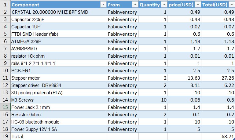
what materials and components will be used? where will they come from? how much will it cost?
what parts and systems will be made? what processes will be used?
The rotating mechanism was made with 3D printing. The control board was made by milling and soldering. Vynal cutting is used for decorating with stickers.
how will it be evaluated?
From the smartphone/PC the rotation of the AUT is controlled. When changing the rotation angle from the application, the system should rotate only that angle. The rotating mechanism has to be decided in order to optimize the power consumption and smooth control of the system. Moreover, the coding of the control board has to be done parallel with the application development for controlling the rotation of the system.
Electronics Design and Production
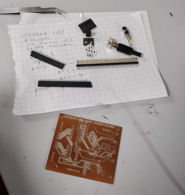
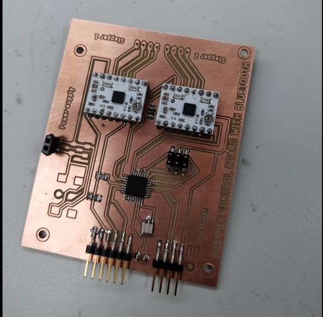
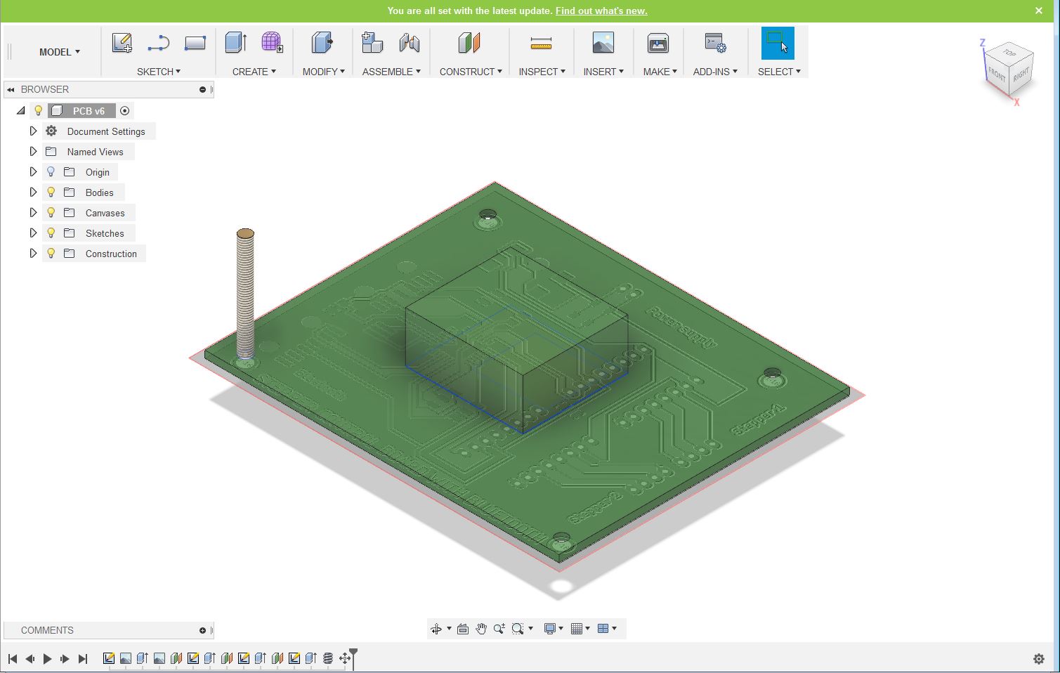
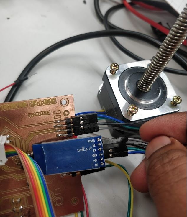
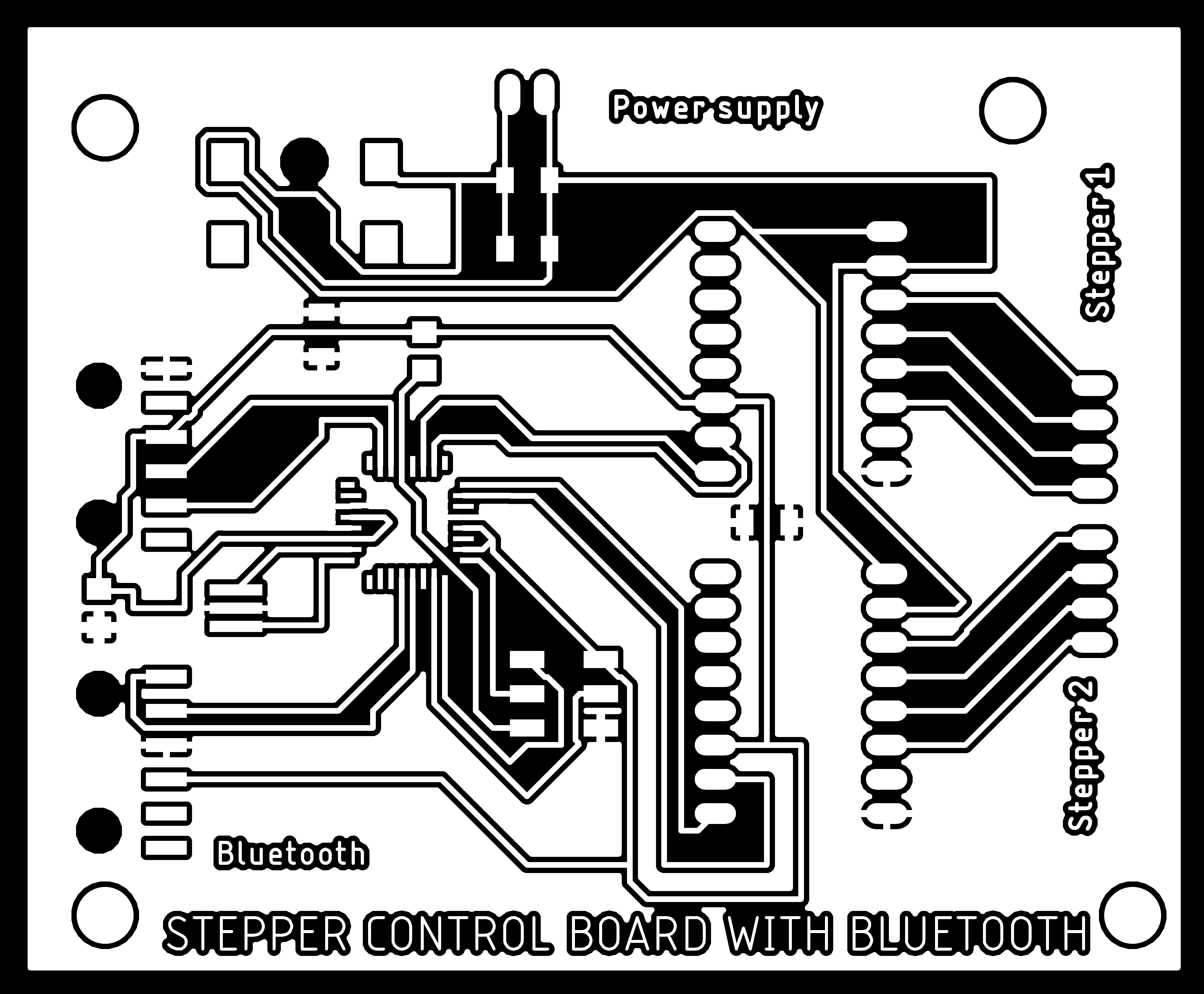
For the designing of the control board, I decided to use ATmega 328P microcontroller because I needed more GPIO pins to control two stepper motors as well as the Bluetooth module. First I designed the schematic from Eagle with all components. I kept rails for the DRV8834 stepper driver modules and connectors for stepper motors. Moreover, I added 12V power input jack to ease of power input. And also kept some pins for the Bluetooth module connection as well.
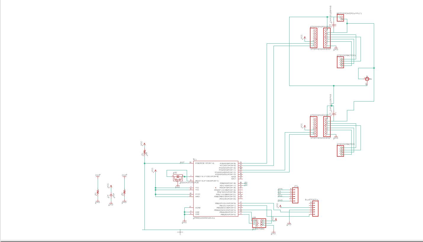
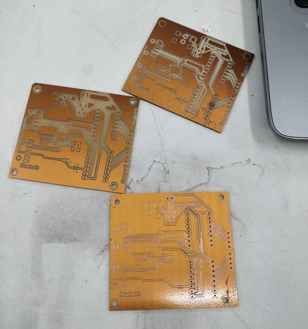
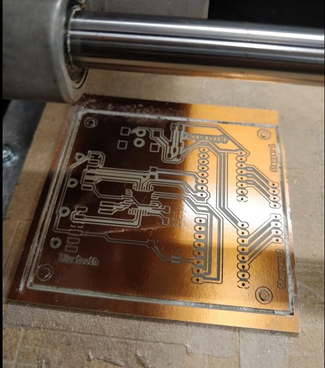
Next, I designed the layout corresponding to the schematic. I added some text layers in addition to the traces. After that, I exported three images for the milling board as the traces without holes, holes only and the outline. The milling procedure is described in the electronics production week. I had to mill the board a few times due to milling issues such as too narrow traces..etc
Mechanical design and 3D printing
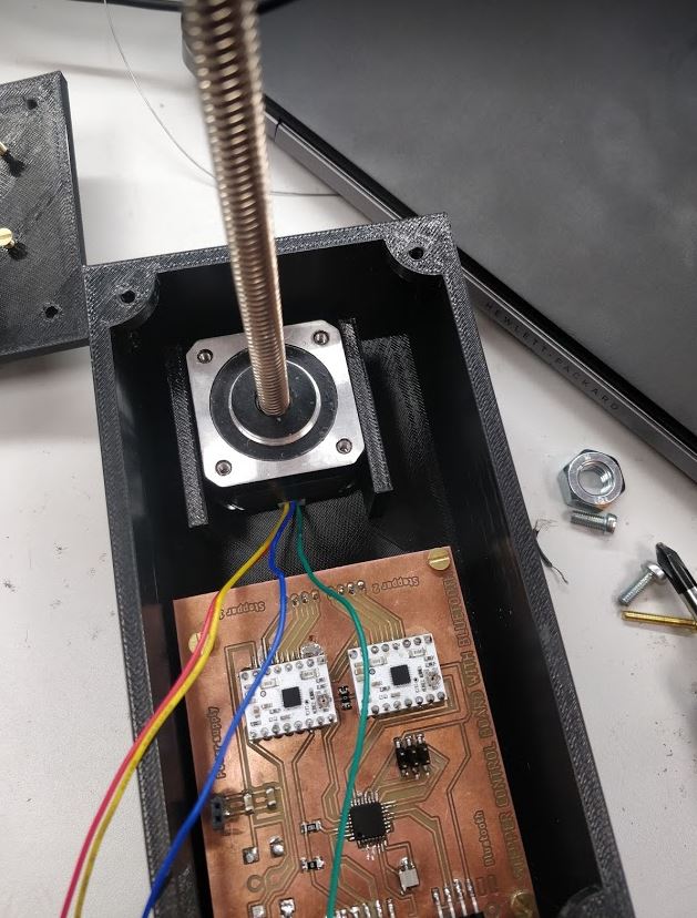
First I needed to arrange my two stepper motors in a way that one can change the azimuth angle of the AUT and the other has to change the elevation angle. Therefore, I decided to use the Bipolar stepper motor with 28cm lead screw and the other one as 4 phase 12V DC unipolar stepper motor. After taking the measurement from these and making the models in the fusion 360 really helped me later on while designing the package for my project. After that, I modeled my PCB for exact dimentions again on fusion 360.
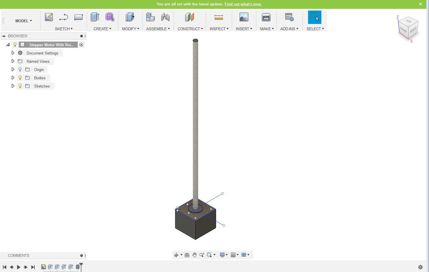
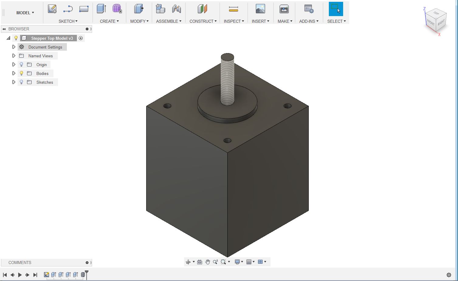
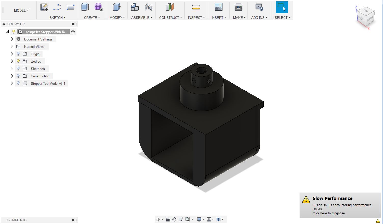
After modeling all components in my project it was time to place them in a way such that I could control the rotation. I decided to put my control board and the Bipolar stepper motor with 28cm lead screw on the bottom and on top of that, I put the 4 phase 12V DC unipolar stepper motor.
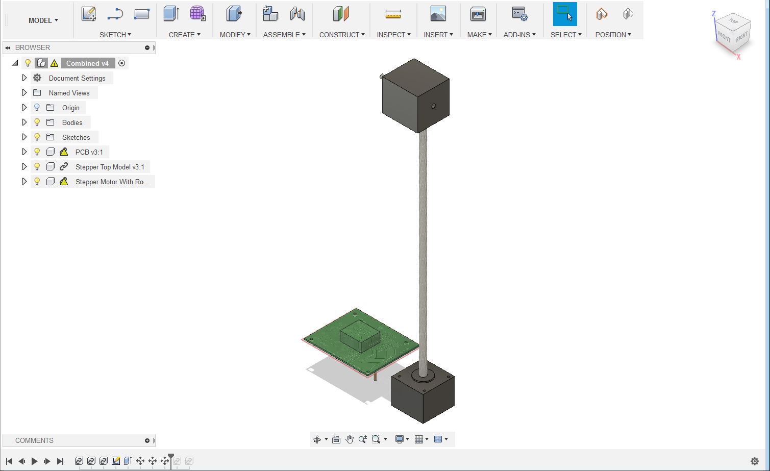
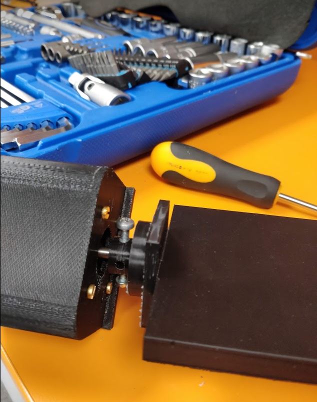
Then it was time to design the platform to hold the top stepper motor and another platform to mount the antenna. For my project, I just need the rotation of the platform and it does not have to travel up and down when rotating. Therefore, I needed to make it fixed to the screw of the motor. After consulting with local instructors I designed these platforms in a way that they could be fixed to stepper motors with M3 screws. After that, I added some exclosure parts to them for mounting an antenna and fixing the 4 phase 12V DC unipolar stepper motor on top of the other motor.
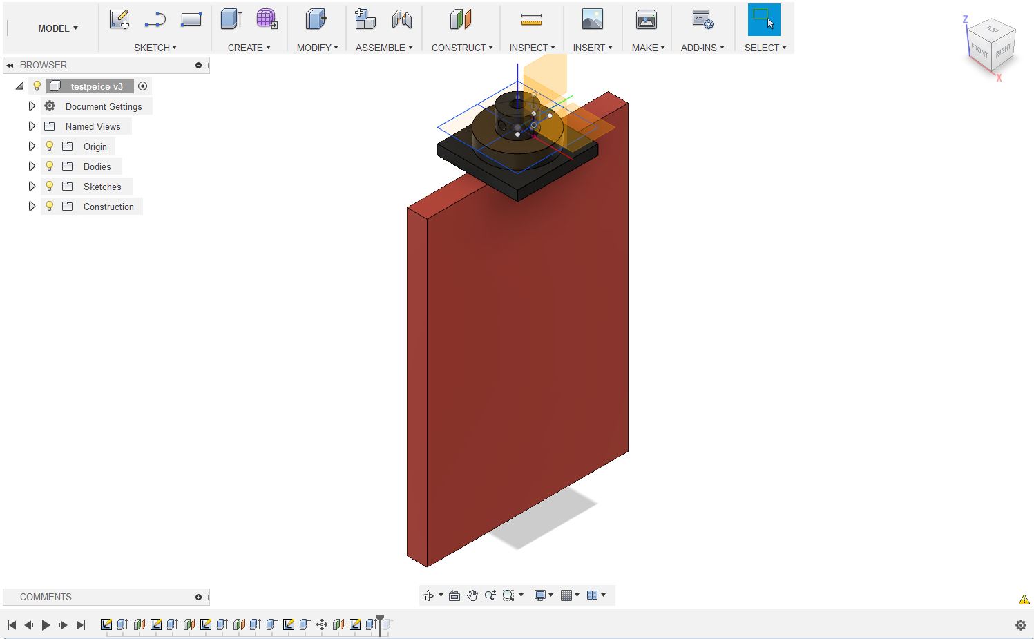
After that, I designed the bottom box for my project. While designing the box I had to take in to account the power input for the control board and the wires from the stepper motors as well as the HC06 Bluetooth module. After that, the lid of the box was designed considering that the control board and the Bipolar stepper motor with 28cm lead screw can be fixed to the box with screws.
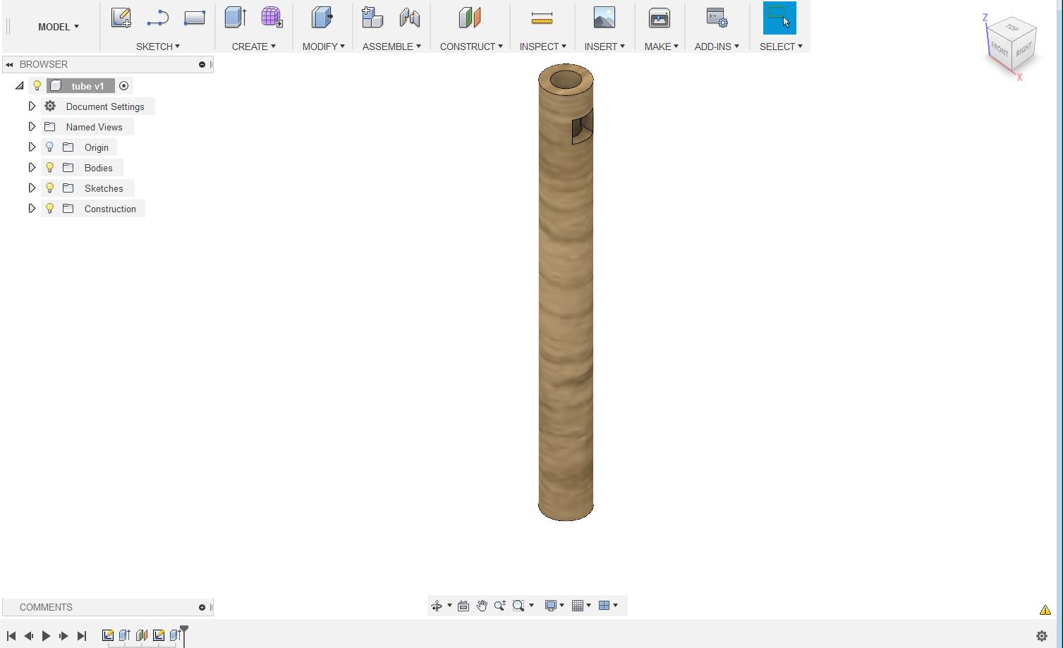
The final step was to design a circular tube to cover up the 28cm lead screw of the bottom stepper motor. Here I had to consider the wires from 4 phase 12V DC unipolar stepper motor. which is at the end of the screw has to travel through this tube. After that, These parts were ready to be printed. I printed total of 5 these parts seperately.
Programming of the board and Making a custom application
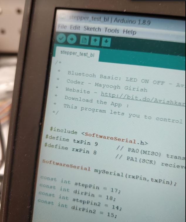
PCB for my final project is built using ATmega328. I used the Arduino IDE to do all the programming. More about programming can be found on the Week 9 Embedded Programming page.
To begin with, I burned the bootloader with an external 20MHz clock. After successfully burning the bootloader, the next step was to control the stepper motors. I used DRV8834 stepper driver modules to control the stepper motors. I used the modified Output week 12 codes to check the stepper motors. Next, I used the Bluetooth module to control the stepper motors. Here I used the modified codes from Networking week.
After I checked all the functionalities of the board, the next step was to make a custom app to control the stepper motor rotations using Bluetooth.
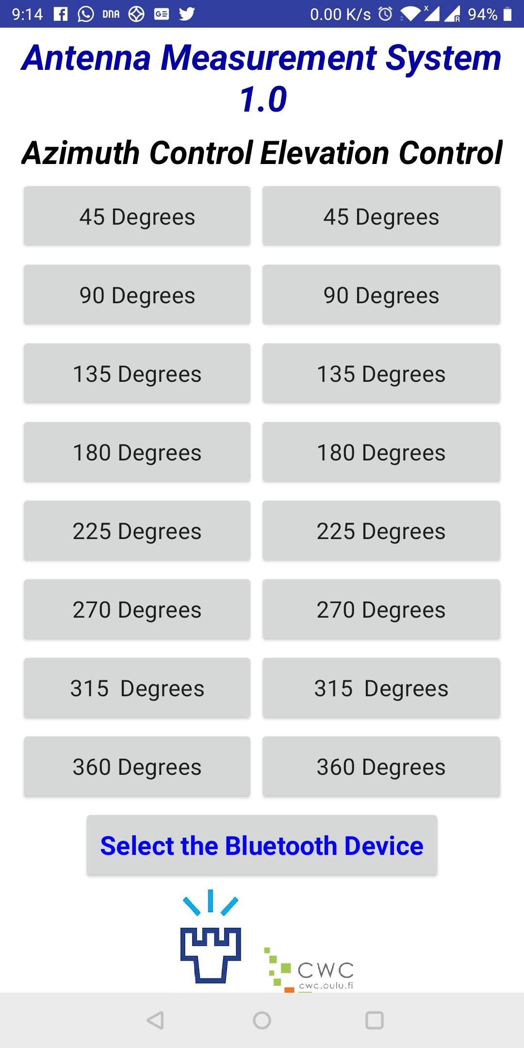
I used the MIT app inventor to make the application. After watching some tutorials on the page I proceeded to make my app. Initially, I designed the interface. My idea was to have different controls for changing the azimuth angle and the elevation angle. Therefore I designed different buttons for different angles for controlling both angles. I added a drop-down menu for selecting the Bluetooth device. Moreover, I added some logos for the interface as well.
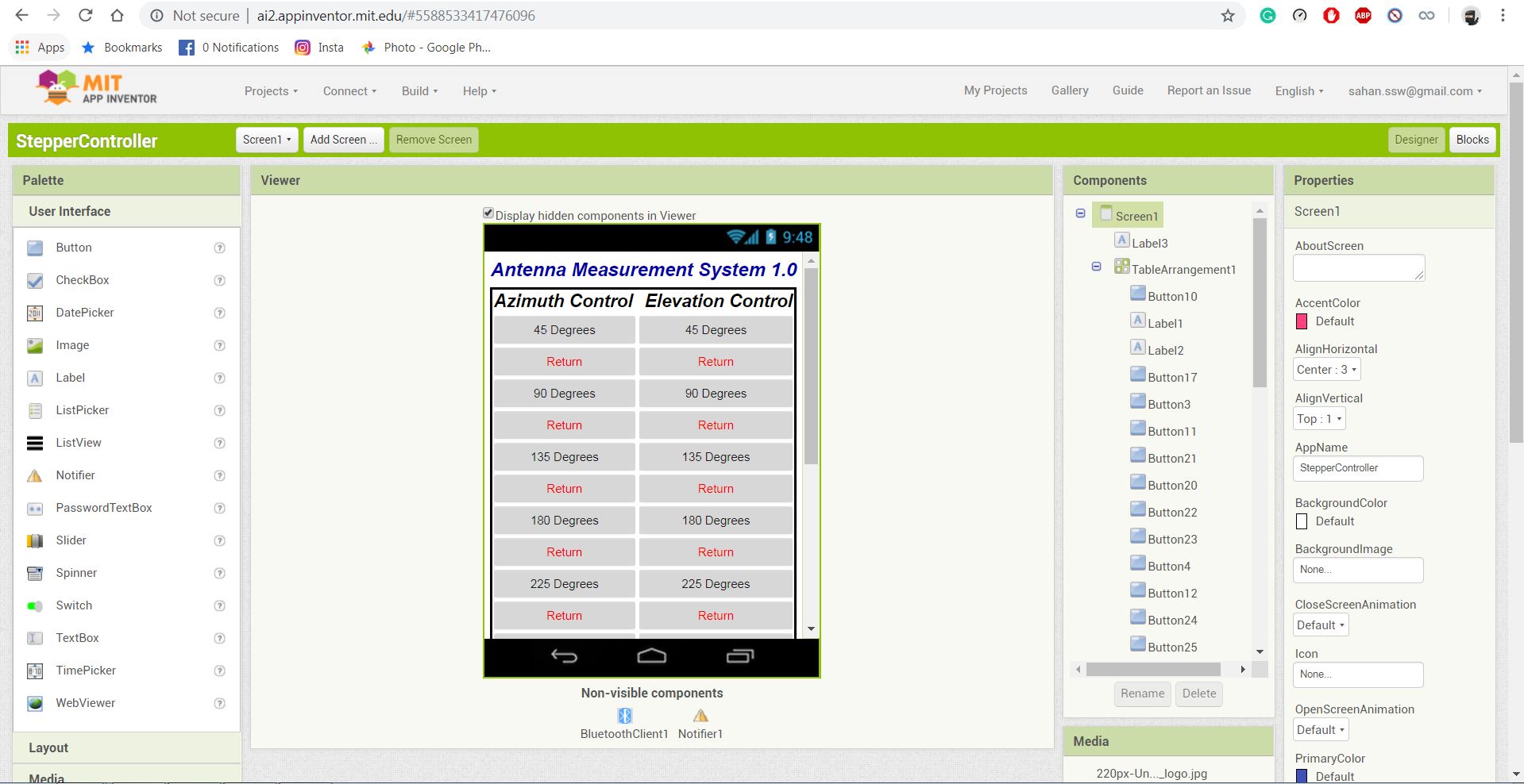
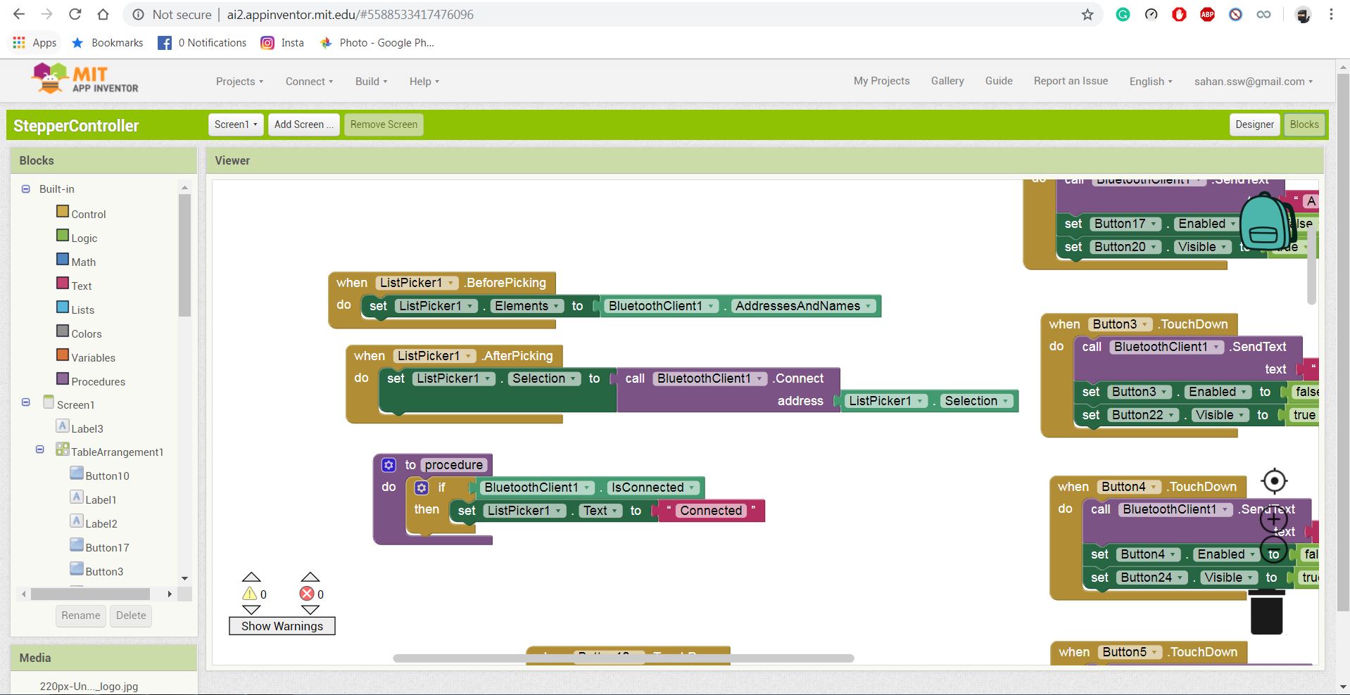
Next step was to program the app. It was much easier since the MIT app inventor uses function blocks to program. I programmed the app such that it sends different characters when different buttons are pressed. After that, I downloaded the APK file from the website.
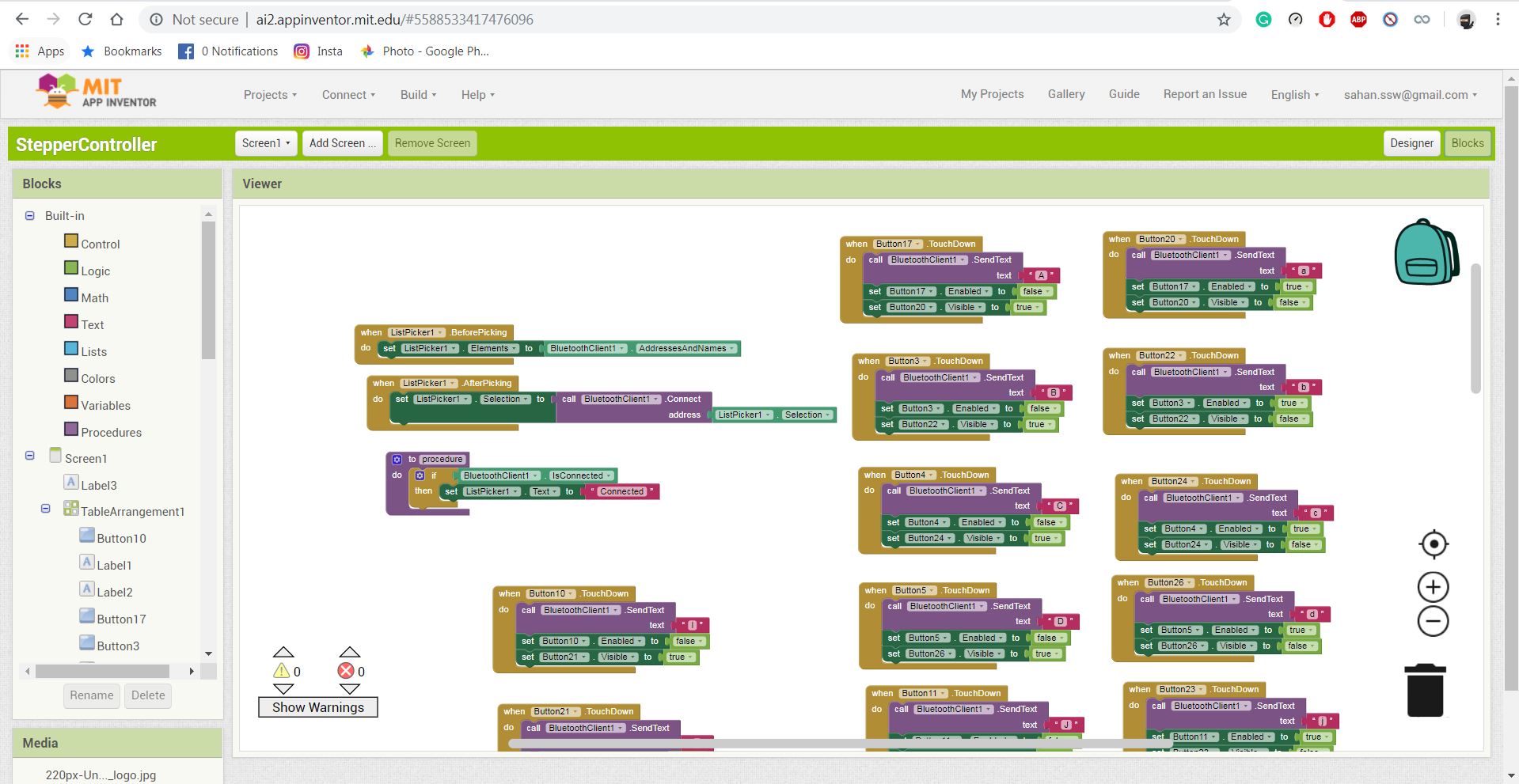
The final step for programming was to program the microcontroller to send signals to stepper drivers according to the input signals from the Bluetooth module. The code is shown below
#include
#define txPin 9     // PA0(MISO) transmit signal to the bridge
#define rxPin 8     // PA1(SCK) recieves signal from bridge

SoftwareSerial mySerial(rxPin, txPin);

const int stepPin = 17;
const int dirPin = 18;
const int stepPin2 = 14;
const int dirPin2 = 15;


char Incoming_value = 0;                //Variable for storing Incoming_value
void setup()
{
  mySerial.begin(9600);         //Sets the data rate in bits per second (baud) for serial data transmission
  pinMode(txPin, INPUT);   //default tx as input
  pinMode(stepPin, OUTPUT);
  pinMode(dirPin, OUTPUT);
  pinMode(stepPin2, OUTPUT);
  pinMode(dirPin2, OUTPUT);
}
void loop()
{
  if (mySerial.available() > 0)
  {
    Incoming_value = mySerial.read();      //Read the incoming data and store it into variable Incoming_value
    mySerial.print(Incoming_value);        //Print Value of Incoming_value in Serial monitor
    mySerial.print("\n");        //New line
    if (Incoming_value == 'A')
    {
      digitalWrite(dirPin, LOW); // Enables the motor to move in a particular direction
      // Makes 800 pulses for making one full cycle rotation
      for (int x = 0; x < 100; x++) {
        digitalWrite(stepPin, HIGH);
        delay(1);  // ms
        digitalWrite(stepPin, LOW);
        delay(1);
      }
    }
    if (Incoming_value == 'a')
    { digitalWrite(dirPin,  HIGH);
      for (int x = 0; x < 100; x++) {
        digitalWrite(stepPin, HIGH);
        delay(1);  // ms
        digitalWrite(stepPin, LOW);
        delay(1);
      }
    }
    if (Incoming_value == 'B')
    {
      digitalWrite(dirPin, LOW); // Enables the motor to move in a particular direction
      // Makes 800 pulses for making one full cycle rotation
      for (int x = 0; x < 200; x++) {
        digitalWrite(stepPin, HIGH);
        delay(1);  // ms
        digitalWrite(stepPin, LOW);
        delay(1);
      }
    }
    if (Incoming_value == 'b')
    {
      digitalWrite(dirPin,  HIGH); // Enables the motor to move in a particular direction
      // Makes 800 pulses for making one full cycle rotation
      for (int x = 0; x < 200; x++) {
        digitalWrite(stepPin, HIGH);
        delay(1);  // ms
        digitalWrite(stepPin, LOW);
        delay(1);
      }
    }
    if (Incoming_value == 'C')
    {
      digitalWrite(dirPin, LOW); // Enables the motor to move in a particular direction
      // Makes 800 pulses for making one full cycle rotation
      for (int x = 0; x < 300; x++) {
        digitalWrite(stepPin, HIGH);
        delay(1);  // ms
        digitalWrite(stepPin, LOW);
        delay(1);
      }
    }
if (Incoming_value == 'c')
    {
      digitalWrite(dirPin,  HIGH); // Enables the motor to move in a particular direction
      // Makes 800 pulses for making one full cycle rotation
      for (int x = 0; x < 300; x++) {
        digitalWrite(stepPin, HIGH);
        delay(1);  // ms
        digitalWrite(stepPin, LOW);
        delay(1);
      }
    }
    if (Incoming_value == 'D')
    {
      digitalWrite(dirPin, LOW); // Enables the motor to move in a particular direction
      // Makes 800 pulses for making one full cycle rotation
      for (int x = 0; x < 400; x++) {
        digitalWrite(stepPin, HIGH);
        delay(1);  // ms
        digitalWrite(stepPin, LOW);
        delay(1);
      }
    }
    if (Incoming_value == 'd')
    {
      digitalWrite(dirPin,  HIGH); // Enables the motor to move in a particular direction
      // Makes 800 pulses for making one full cycle rotation
      for (int x = 0; x < 400; x++) {
        digitalWrite(stepPin, HIGH);
        delay(1);  // ms
        digitalWrite(stepPin, LOW);
        delay(1);
      }
    }
    if (Incoming_value == 'E')
    {
      digitalWrite(dirPin, LOW); // Enables the motor to move in a particular direction
      // Makes 800 pulses for making one full cycle rotation
      for (int x = 0; x < 500; x++) {
        digitalWrite(stepPin, HIGH);
        delay(1);  // ms
        digitalWrite(stepPin, LOW);
        delay(1);
      }
    }
     if (Incoming_value == 'e')
    {
      digitalWrite(dirPin,  HIGH); // Enables the motor to move in a particular direction
      // Makes 800 pulses for making one full cycle rotation
      for (int x = 0; x < 500; x++) {
        digitalWrite(stepPin, HIGH);
        delay(1);  // ms
        digitalWrite(stepPin, LOW);
        delay(1);
      }
    }
    if (Incoming_value == 'F')
    {
      digitalWrite(dirPin, LOW); // Enables the motor to move in a particular direction
      // Makes 800 pulses for making one full cycle rotation
      for (int x = 0; x < 600; x++) {
        digitalWrite(stepPin, HIGH);
        delay(1);  // ms
        digitalWrite(stepPin, LOW);
        delay(1);
      }
    }
    if (Incoming_value == 'f')
    {
      digitalWrite(dirPin,  HIGH); // Enables the motor to move in a particular direction
      // Makes 800 pulses for making one full cycle rotation
      for (int x = 0; x < 600; x++) {
        digitalWrite(stepPin, HIGH);
        delay(1);  // ms
        digitalWrite(stepPin, LOW);
        delay(1);
      }
    }
    if (Incoming_value == 'G')
    {
      digitalWrite(dirPin, LOW); // Enables the motor to move in a particular direction
      // Makes 800 pulses for making one full cycle rotation
      for (int x = 0; x < 700; x++) {
        digitalWrite(stepPin, HIGH);
        delay(1);  // ms
        digitalWrite(stepPin, LOW);
        delay(1);
      }
    }
    if (Incoming_value == 'g')
    {
      digitalWrite(dirPin,  HIGH); // Enables the motor to move in a particular direction
      // Makes 800 pulses for making one full cycle rotation
      for (int x = 0; x < 700; x++) {
        digitalWrite(stepPin, HIGH);
        delay(1);  // ms
        digitalWrite(stepPin, LOW);
        delay(1);
      }
    }
    if (Incoming_value == 'H')
    {
      digitalWrite(dirPin, LOW); // Enables the motor to move in a particular direction
      // Makes 800 pulses for making one full cycle rotation
      for (int x = 0; x < 800; x++) {
        digitalWrite(stepPin, HIGH);
        delay(1);  // ms
        digitalWrite(stepPin, LOW);
        delay(1);
      }
    }
    if (Incoming_value == 'h')
    {
      digitalWrite(dirPin, HIGH); // Enables the motor to move in a particular direction
      // Makes 800 pulses for making one full cycle rotation
      for (int x = 0; x < 800; x++) {
        digitalWrite(stepPin, HIGH);
        delay(1);  // ms
        digitalWrite(stepPin, LOW);
        delay(1);
      }
    }
    if (Incoming_value == 'I')
    {
      digitalWrite(dirPin2, LOW); // Enables the motor to move in a particular direction
      // Makes 800 pulses for making one full cycle rotation
      for (int x = 0; x < 100; x++) {
        digitalWrite(stepPin2, HIGH);
        delay(1);  // ms
        digitalWrite(stepPin2, LOW);
        delay(1);
      }
    }
    if (Incoming_value == 'i')
    {
      digitalWrite(dirPin2, HIGH); // Enables the motor to move in a particular direction
      // Makes 800 pulses for making one full cycle rotation
      for (int x = 0; x < 100; x++) {
        digitalWrite(stepPin2, HIGH);
        delay(1);  // ms
        digitalWrite(stepPin2, LOW);
        delay(1);
      }
    }
    if (Incoming_value == 'J')
    {
      digitalWrite(dirPin2, LOW); // Enables the motor to move in a particular direction
      // Makes 800 pulses for making one full cycle rotation
      for (int x = 0; x < 200; x++) {
        digitalWrite(stepPin2, HIGH);
        delay(1);  // ms
        digitalWrite(stepPin2, LOW);
        delay(1);
      }
    }
    if (Incoming_value == 'j')
    {
      digitalWrite(dirPin2, HIGH); // Enables the motor to move in a particular direction
      // Makes 800 pulses for making one full cycle rotation
      for (int x = 0; x < 200; x++) {
        digitalWrite(stepPin2, HIGH);
        delay(1);  // ms
        digitalWrite(stepPin2, LOW);
        delay(1);
      }
    }
    if (Incoming_value == 'K')
    {
      digitalWrite(dirPin2, LOW); // Enables the motor to move in a particular direction
      // Makes 800 pulses for making one full cycle rotation
      for (int x = 0; x < 300; x++) {
        digitalWrite(stepPin2, HIGH);
        delay(1);  // ms
        digitalWrite(stepPin2, LOW);
        delay(1);
      }
    }
    if (Incoming_value == 'k')
    {
      digitalWrite(dirPin2, HIGH); // Enables the motor to move in a particular direction
      // Makes 800 pulses for making one full cycle rotation
      for (int x = 0; x < 300; x++) {
        digitalWrite(stepPin2, HIGH);
        delay(1);  // ms
        digitalWrite(stepPin2, LOW);
        delay(1);
      }
    }
    if (Incoming_value == 'L')
    {
      digitalWrite(dirPin2, LOW); // Enables the motor to move in a particular direction
      // Makes 800 pulses for making one full cycle rotation
      for (int x = 0; x < 400; x++) {
        digitalWrite(stepPin2, HIGH);
        delay(1);  // ms
        digitalWrite(stepPin2, LOW);
        delay(1);
      }
    }
    if (Incoming_value == 'l')
      digitalWrite(dirPin2, HIGH); // Enables the motor to move in a particular direction
      // Makes 800 pulses for making one full cycle rotation
      for (int x = 0; x < 400; x++) {
        digitalWrite(stepPin2, HIGH);
        delay(1);  // ms
        digitalWrite(stepPin2, LOW);
        delay(1);
      }
    }
    if (Incoming_value == 'M')
    {
      digitalWrite(dirPin2, LOW); // Enables the motor to move in a particular direction
      // Makes 800 pulses for making one full cycle rotation
      for (int x = 0; x < 500; x++) {
        digitalWrite(stepPin2, HIGH);
        delay(1);  // ms
        digitalWrite(stepPin2, LOW);
        delay(1);
      }
    }
    if (Incoming_value == 'm')
    {
      digitalWrite(dirPin2, HIGH); // Enables the motor to move in a particular direction
      // Makes 800 pulses for making one full cycle rotation
      for (int x = 0; x < 500; x++) {
        digitalWrite(stepPin2, HIGH);
        delay(1);  // ms
        digitalWrite(stepPin2, LOW);
        delay(1);
      }
    }
    if (Incoming_value == 'N')
    {
      digitalWrite(dirPin2, LOW); // Enables the motor to move in a particular direction
      // Makes 800 pulses for making one full cycle rotation
      for (int x = 0; x < 600; x++) {
        digitalWrite(stepPin2, HIGH);
        delay(1);  // ms
        digitalWrite(stepPin2, LOW);
        delay(1);
      }
    }
    if (Incoming_value == 'n')
    {
      digitalWrite(dirPin2, HIGH); // Enables the motor to move in a particular direction
      // Makes 800 pulses for making one full cycle rotation
      for (int x = 0; x < 600; x++) {
        digitalWrite(stepPin2, HIGH);
        delay(1);  // ms
        digitalWrite(stepPin2, LOW);
        delay(1);
      }
    }
    if (Incoming_value == 'O')
    {
      digitalWrite(dirPin2, LOW); // Enables the motor to move in a particular direction
      // Makes 800 pulses for making one full cycle rotation
      for (int x = 0; x < 700; x++) {
        digitalWrite(stepPin2, HIGH);
        delay(1);  // ms
        digitalWrite(stepPin2, LOW);
        delay(1);
      }
    }
    if (Incoming_value == 'o')
    {
      digitalWrite(dirPin2, HIGH); // Enables the motor to move in a particular direction
      // Makes 800 pulses for making one full cycle rotation
      for (int x = 0; x < 700; x++) {
        digitalWrite(stepPin2, HIGH);
        delay(1);  // ms
        digitalWrite(stepPin2, LOW);
        delay(1);
      }
    }
    if (Incoming_value == 'P')
    {
      digitalWrite(dirPin2, LOW); // Enables the motor to move in a particular direction
      // Makes 800 pulses for making one full cycle rotation
      for (int x = 0; x < 800; x++) {
        digitalWrite(stepPin2, HIGH);
        delay(1);  // ms
        digitalWrite(stepPin2, LOW);
        delay(1);
      }
    }
    if (Incoming_value == 'p')
    {
      digitalWrite(dirPin2, HIGH); // Enables the motor to move in a particular direction
      // Makes 800 pulses for making one full cycle rotation
      for (int x = 0; x < 800; x++) {
        digitalWrite(stepPin2, HIGH);
        delay(1);  // ms
        digitalWrite(stepPin2, LOW);
        delay(1);
      }
    }
  }
}
Assembly
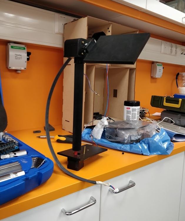
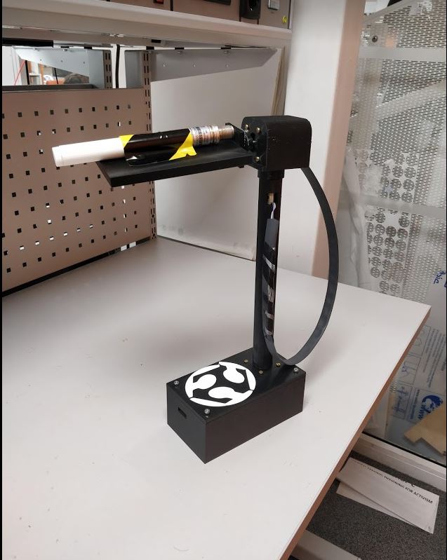
For assembling all the parts for the project I had to use a plier and a screwdriver. It was not that much hard task considering I have designed all the components more precisely. Few snapshots while assembling are shown below.
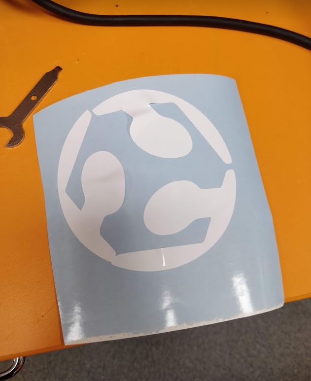
Vinyl cutting
I decided to put a sticker on top of the lid of my bottom part. I used the vinyl cutter to cut a sticker and put it. More about the vinyl cutting can be found on week4.
Workflow timeline
PCB and programming
I started with the electronics design for the final project. On Electronics Design week I learned how to design PCBs in Eagle. Although it took some time to get used to it I was familiar with the process easily. On Output devices week I was able to control a stepper motor with ATtiny44a.It was observed that there are no enough GPIO pins in ATtiny 44a to control two stepper motors as well as a Bluetooth module, therefore, I used ATmega328p for the final electronics design. On Embedded programming week I started the first version of the firmware. I used Arduino IDE all way long for programming.
Mechanical parts
I started to think about the final design of the mechanical parts after testing the control board. The 3D scanning and printing week was helpful for designing. On this week I started to use Fusion360. Since I was familiar with the software I was able to complete my final design within two days although it took another two days to print all the components considering the rush in the Fablab.
License
On Week 19 I described and chose the license for my project. I decided to use the creative commons attribution license for nonsoftware of my project which allows copying, distribute, display and perform the work and makes derivative works and remixes based on my project when people who reuse my project give the credits (attribution) by acknowledgment. For the software of my project I will use The MIT license.The MIT license allows reusing works with an only very limited restriction that all copies of the licensed software include a copy of the MIT License terms and the copyright notice.
Final Poster
Final Video
Model files
schematic for PCB
pcb image without holes
pcb outline image
pcb holes image
rml file for traces
rml file for outline
rml file for holes
svg file for vinal cutting
stl file for bottom 3D part
stl file for box design
stl file for the lid of the box
stl file of the top mount
stl file for the tube
F3z file for the bottom part
F3z file for top part
F3d file for tube
Code for the microcontroller
apk file for the app