Week 4. COMPUTER-CONTROLLED CUTTING
The main objectives were to Characterize the laser cutter, making test parts that vary cutting settings and dimensions.In addition to that to do a parametric press-fit construction kit and a make a design using vinylcutter.
Characterization of the laser cutter
The concept of Kerf was new to me so I tried to understand what kerf is first. The basic definition of kerf is that it is the width of material that is removed by a cutting process.
Moreover, Vector cutting and Raster cutting concepts were also new to me. Basically, using the vector cutting it is possible to cut material from the laser cutter and using the raster cutting we can etch different styles on the material. These will depend on the printer settings which explained below.
The group assignment
As the group assignment Kerf was measured for 2 materials. MDF and the Acrylic were chosen as the materials because they are easily accessible.The materials selected for laser cutting are MDF and Acrylic (3 mm thickness).
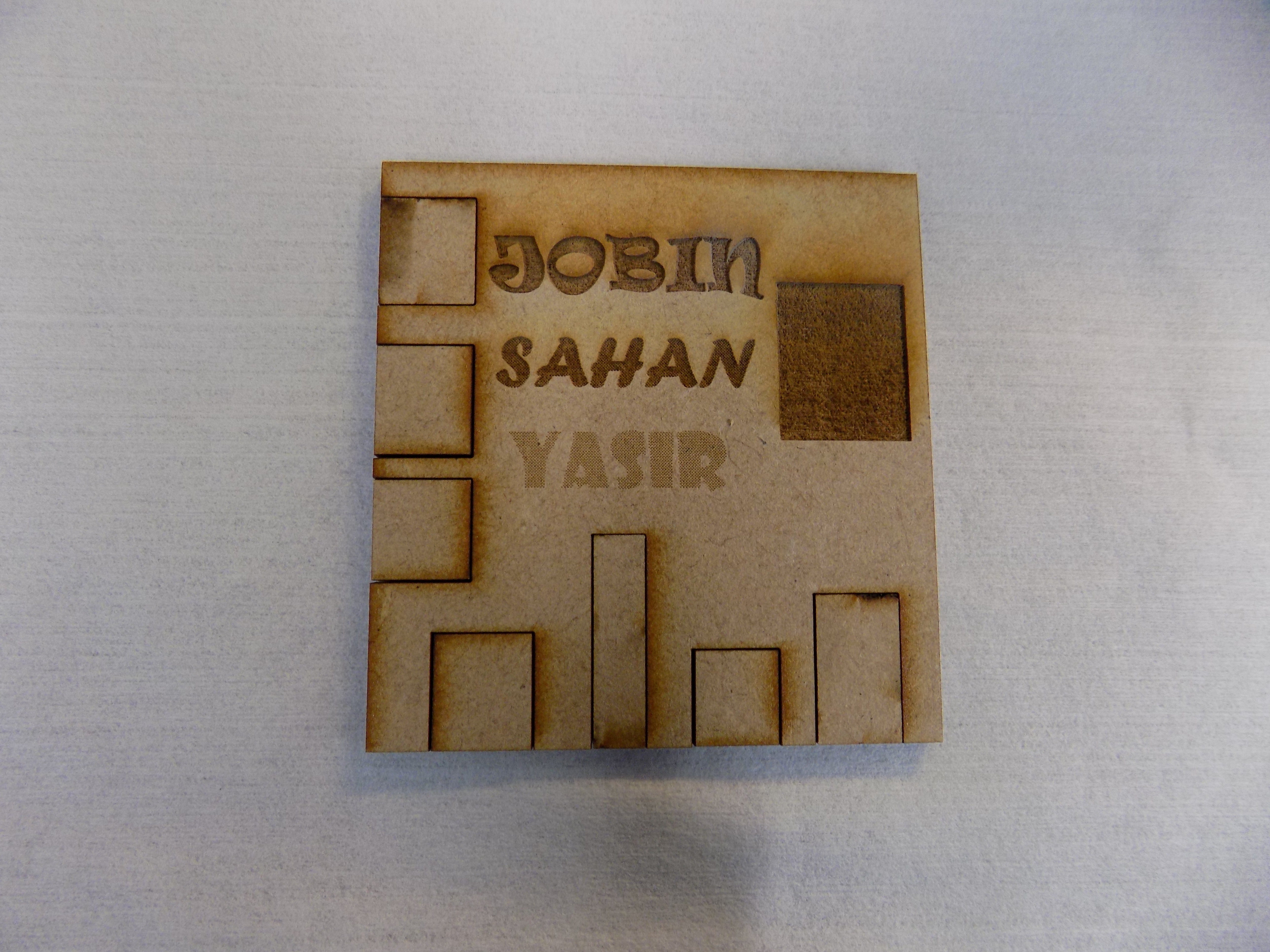
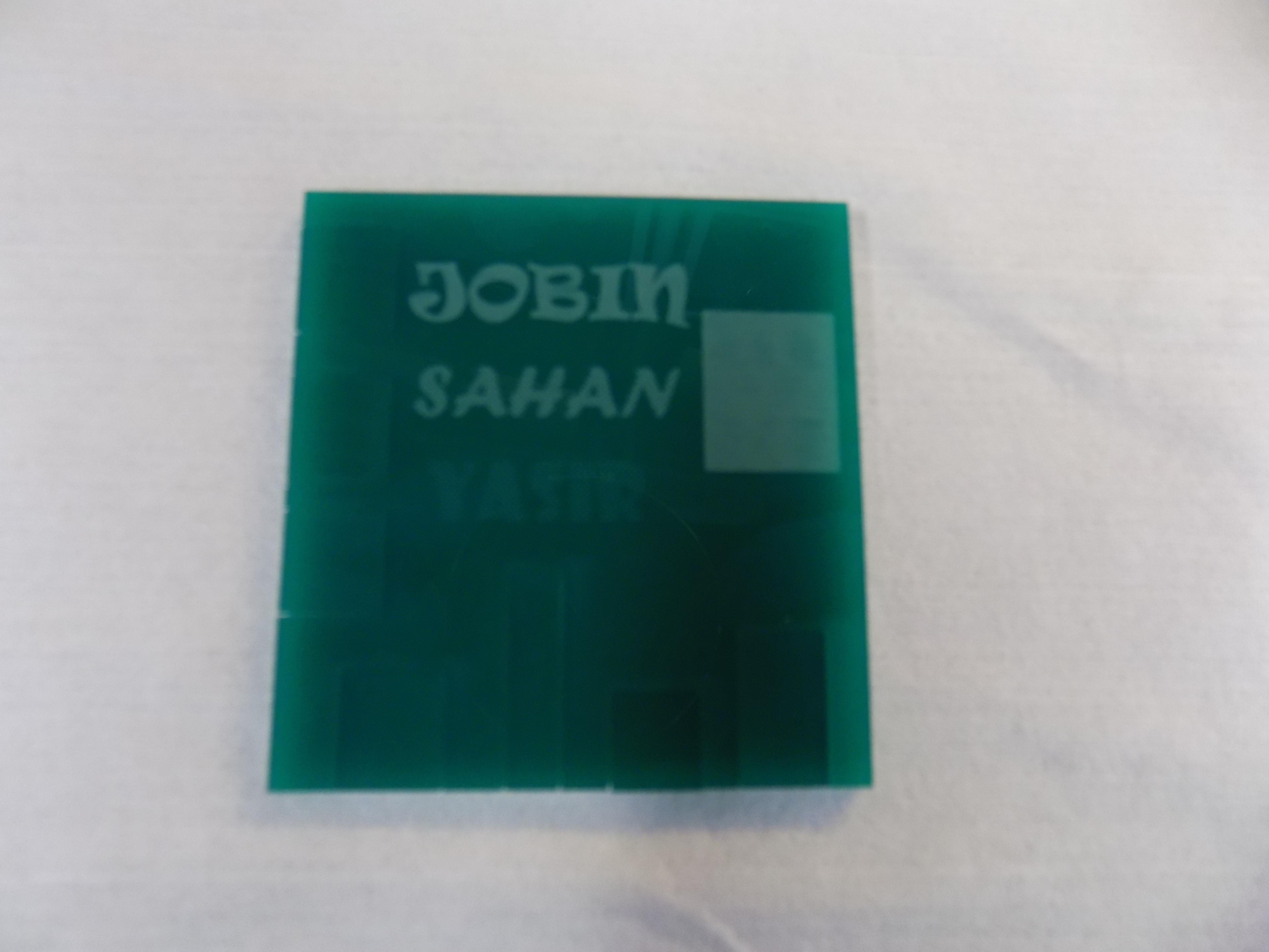
First, a design was made in Inkscace which Kerf can be measured. Epilog Laser Fusion 75 W Laser cutting machine was used to cut the design.
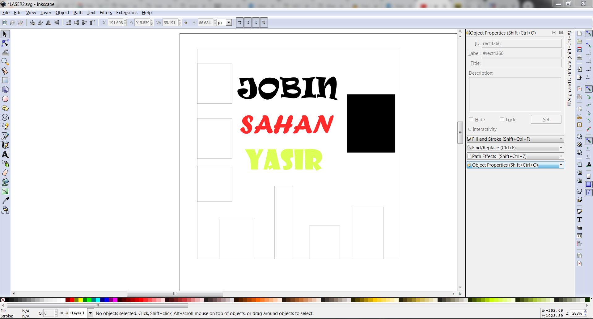
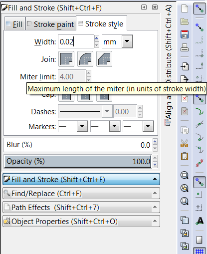
The rectanges on the design were made using the rectangles tool. Moreover, different colors were given to our name texts to see the effect. For vector cutting the line width of 0.02mm was used. Different sizes of rectangles were made to measure the average kerf.
Preparing the machine
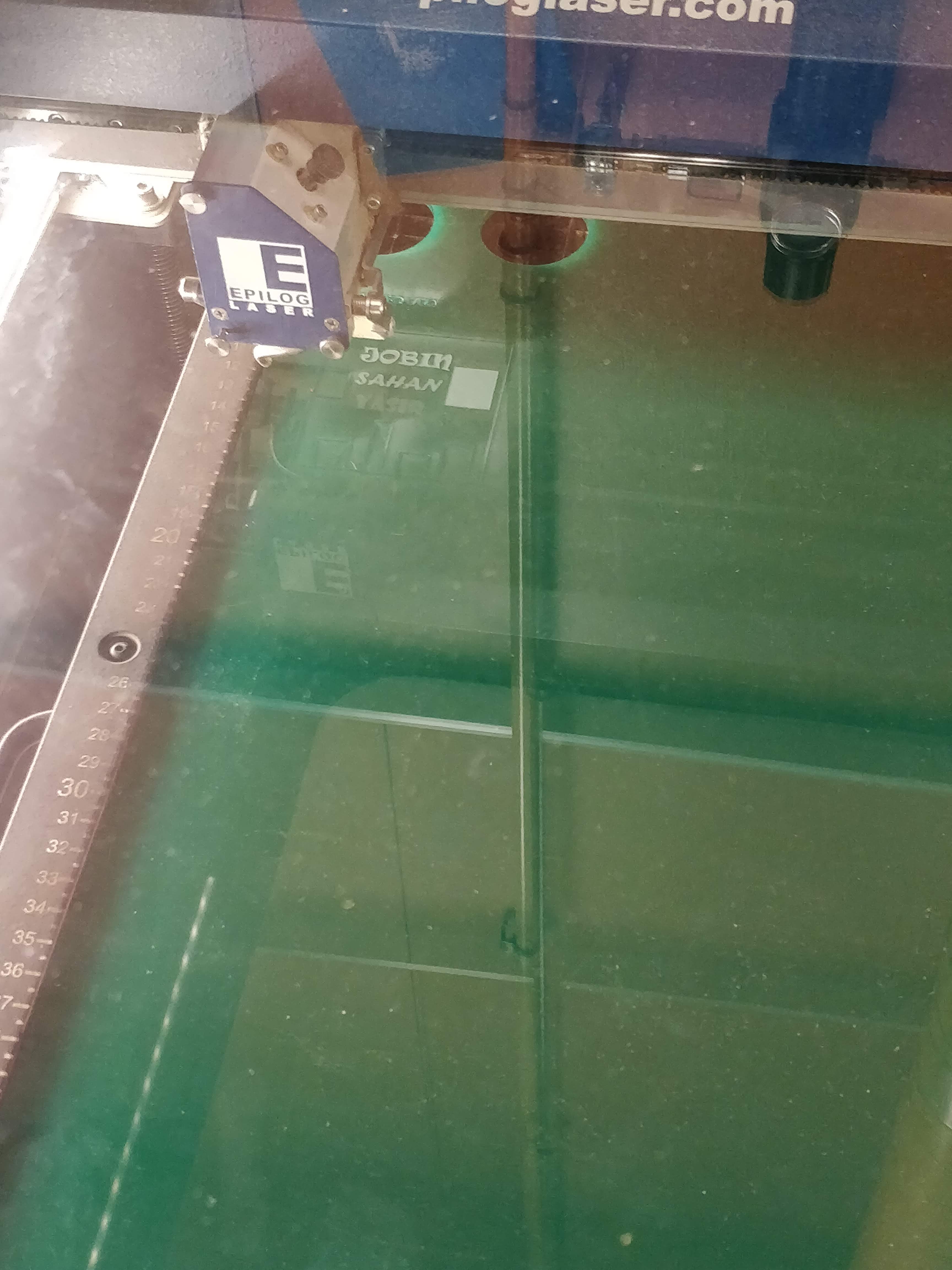
Epilog Laser Fusion 75 W Laser cutting machine was used to cut the design.
As the first step, we have to check whether the ventilation and the air pressure are on.
Next, calibrate the Focus. This process positions the material at a given distance from the laser head. The calibration process is done by a metallic triangle you hang from the laser head. We can select the focus option in the menu and move the horizontal plane up and down until the material touches barely the triangle.
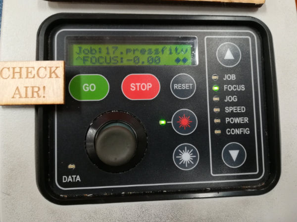
Next, origin has to be set up. This determines where the machine will start to cut. Normally in given settings, it starts at the top left corner of the drawing. After selecting the Jog option in the menu and change the position of the laser head with the joystick accordingly. pressing the joystick when will set up the origin of the design.
Finally, select Job option in the menu and select the file from the list and press Go button.
Measurements with different settings
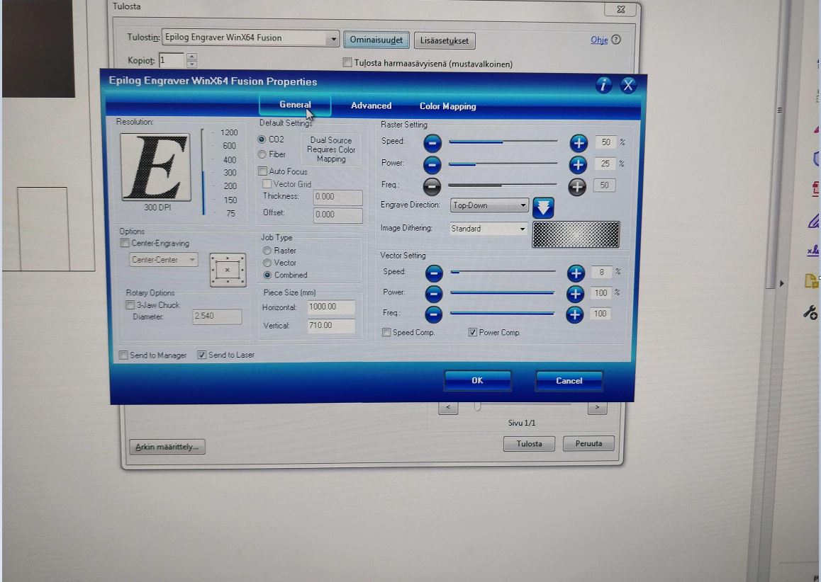
Basically, there are 3 options which can be changed when printing the design. They are Power, Frequency, and Speed. For measuring the Kerf, we decided to change each of these parameters and see the change of Kerf.
First, MDF was selected as the material. First default settings were used to cut vector and raster. Then speed, power, and the frequency percentages were changed in the printer. The measurements are shown below.
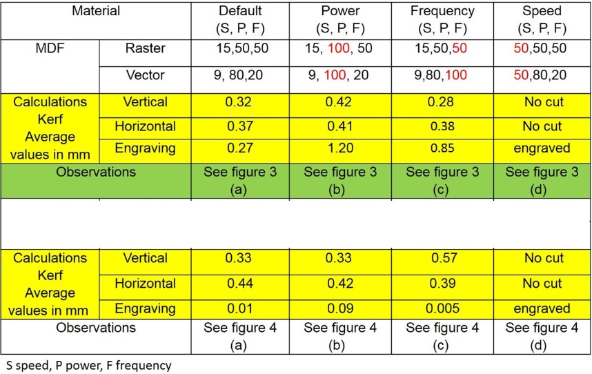
In conclusion, when increasing power the average kerf has increased. Moreover, when frequency increased, The measurement of the kerf has decreased. When speed increased There is not much difference in raster parts of the design but some vector parts were not cut properly.
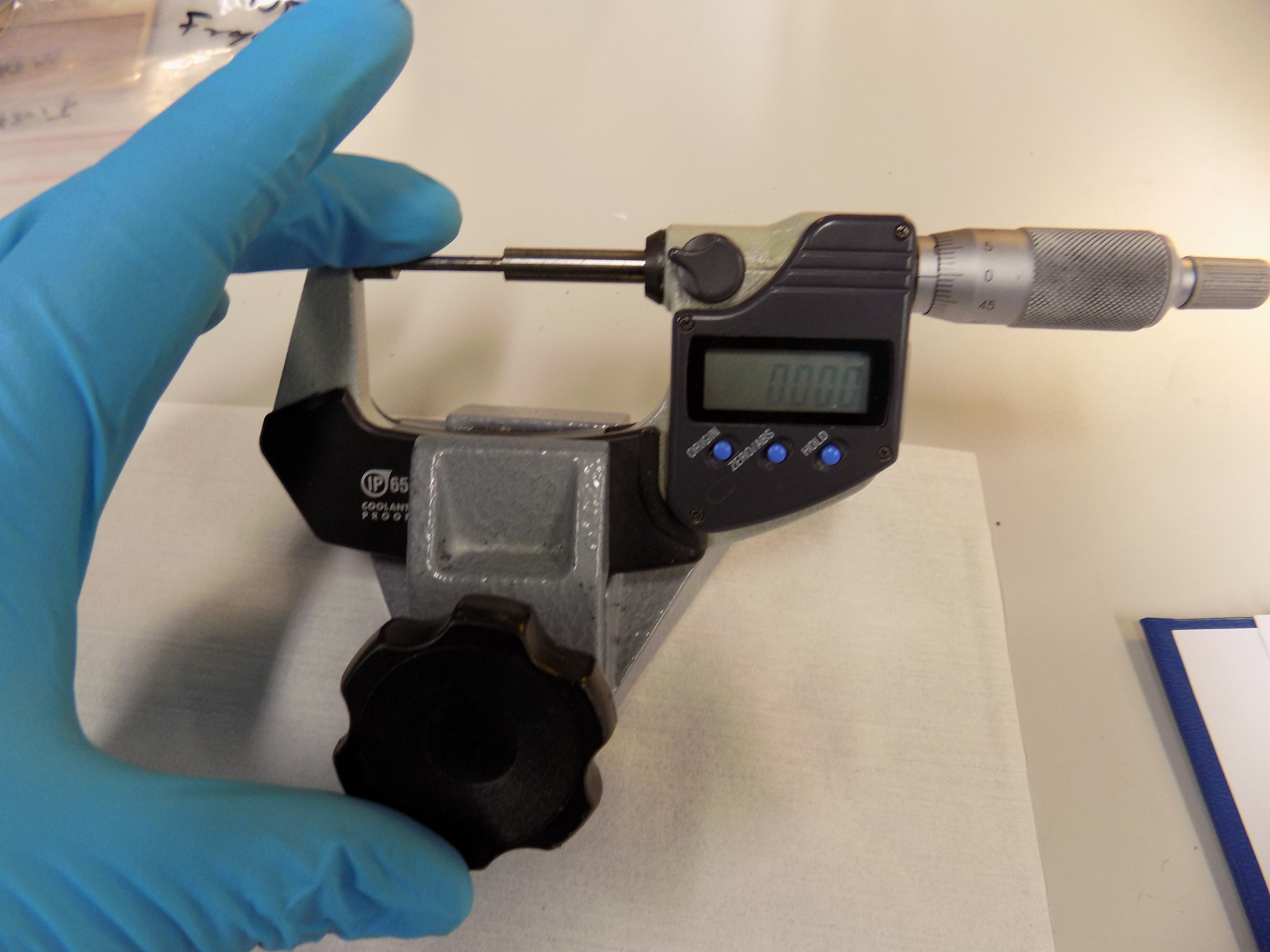
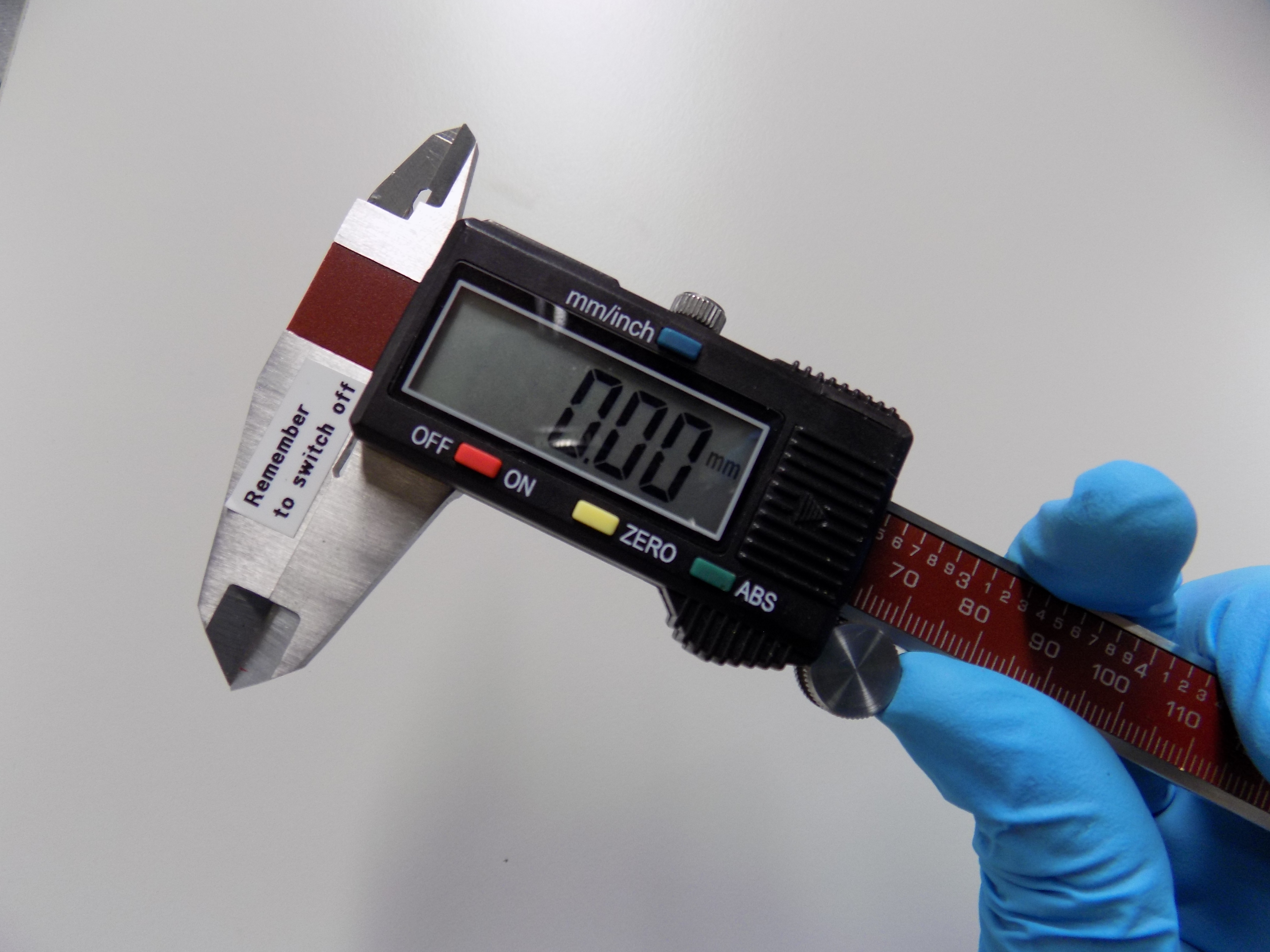
Considering Acrylic as material, the same test was done. Like in the earlier test when power increased the kerf was almost similar to the default state of cutting. However, with increased frequency, there are some fluctuations in the average kerf value. With increased speed, almost the same observations were made as in MDF material. The Vernier calliper used for measuring the cut area and cut a piece of material after laser cutting. The micrometre screw gauge is used for the engraving area. The Vernier has an accuracy of 0.1 mm, and screw gauge has an accuracy of 0.01 mm. Both measurement equipment are also shown in the figure.
It can be observed that from the laser characteristics results, laser parameters such as power, frequency, and speed are interrelated. Low power is needed for cutting the sample. Raster mode which controls the engraving, we noticed that image color also influences the engraving. Laser characteristics also influence on the engraving. The kerf value calculated based on the cut piece and cut area. Engraved kerf measured by actual thickness before cutting and after engraved area. Materials properties are also factors which have a critical influence on laser characteristics.
Vinyl Cutting
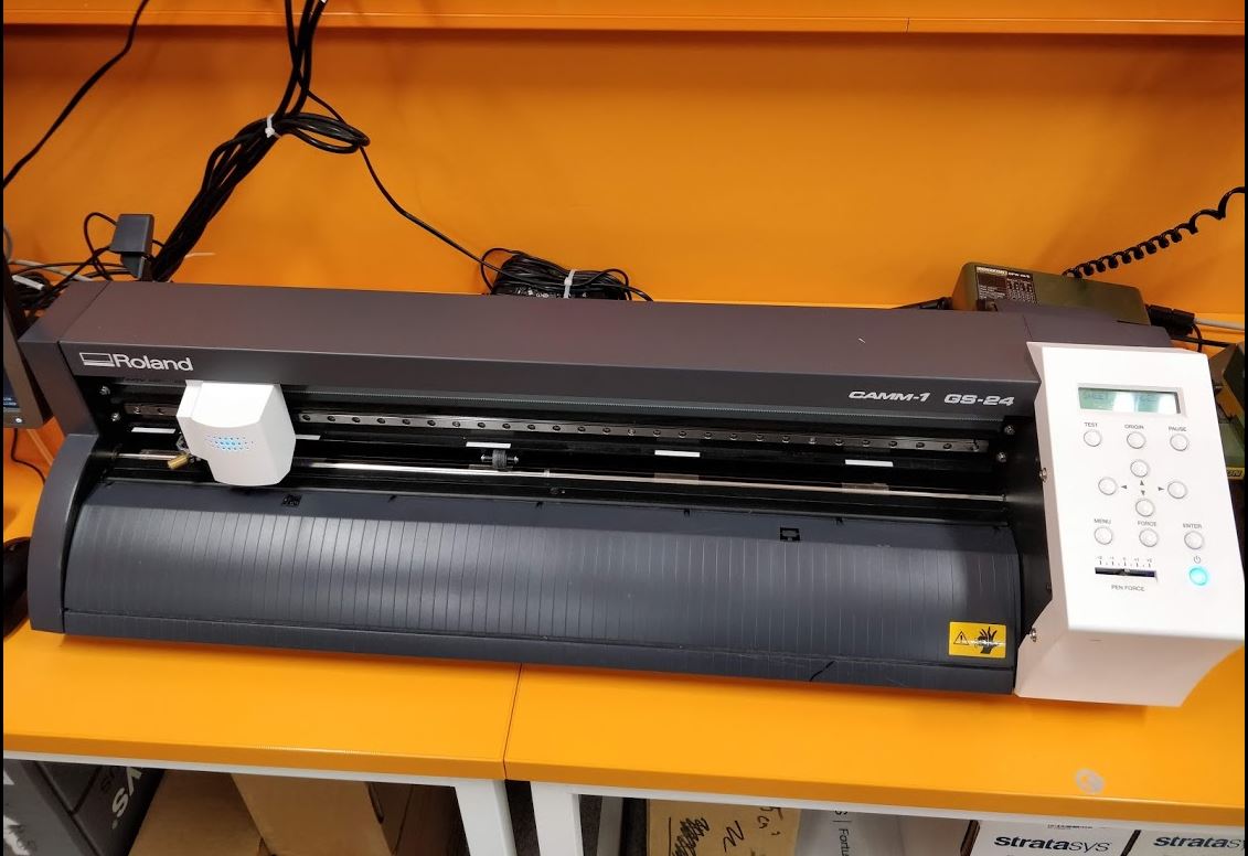
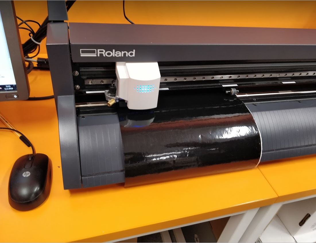
To begin with the vinyl cutting process, I tried to get familiar with the machine. Our fab lab has Roland GS24 cutter. In the process of vinyl cutting, the vinyl cutter cuts the material as we want instead of printing with the ink. Therefore we need to give files with vector graphics. I have used Inkscape to make a vector design.
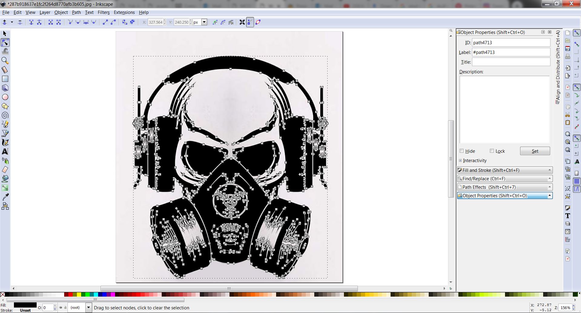
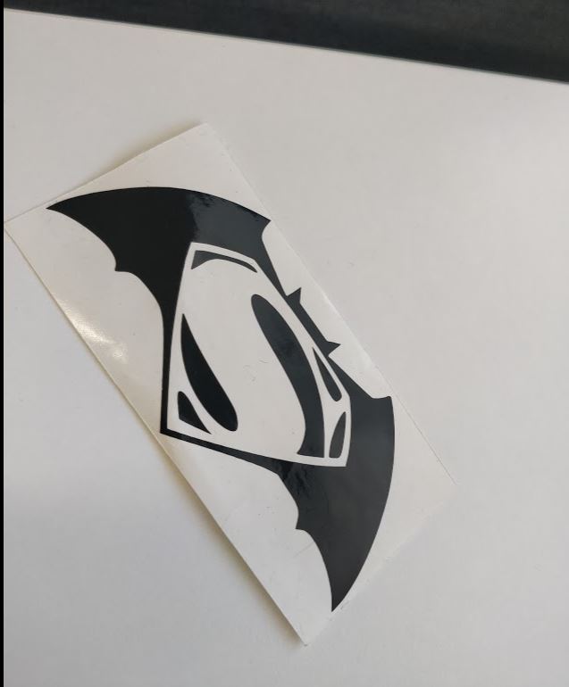
I wanted to make a sticker for my laptop therefore first I downloaded this good design which I liked from pintrest web site. Then I opened it with Inkscape.
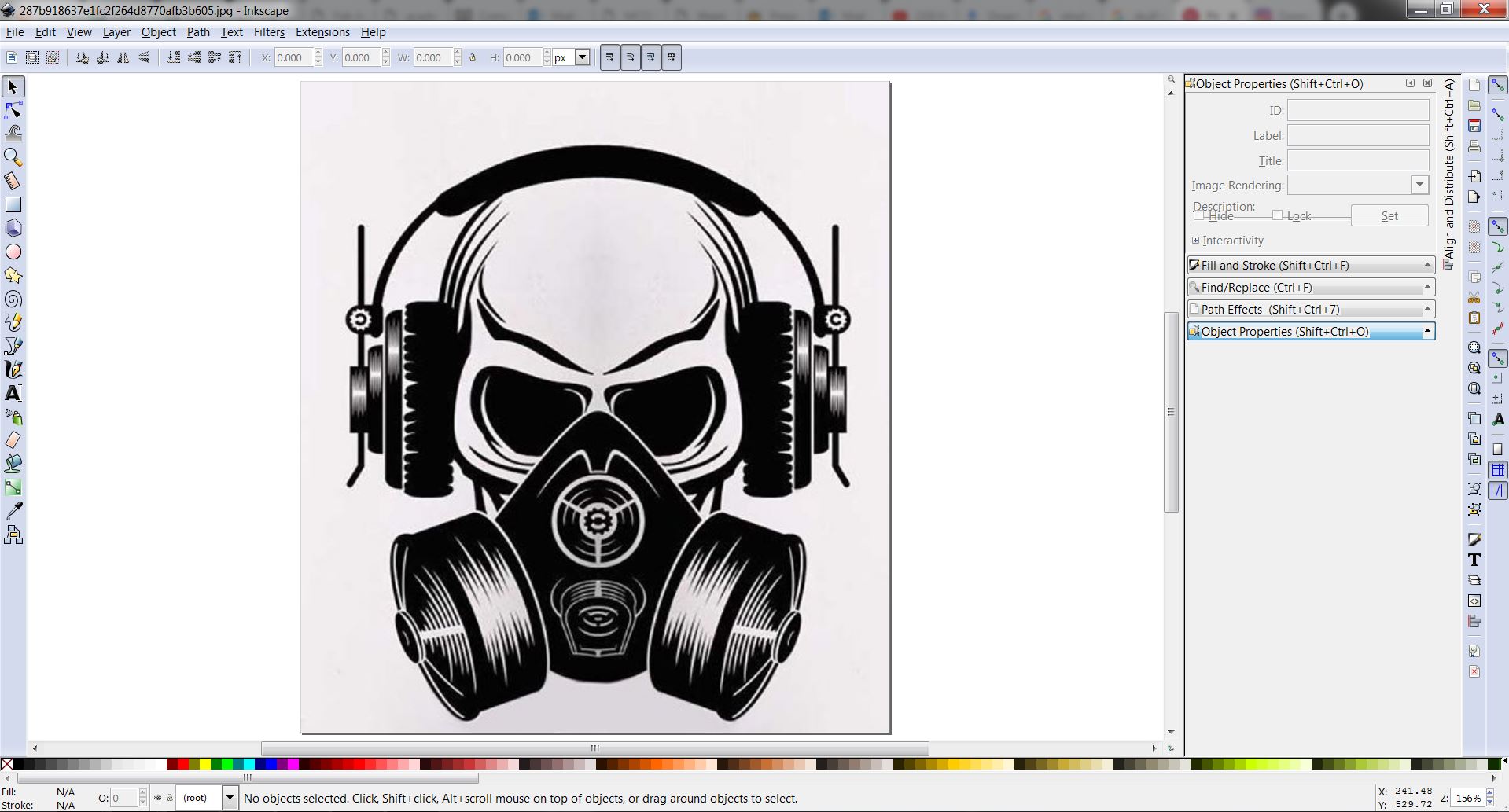
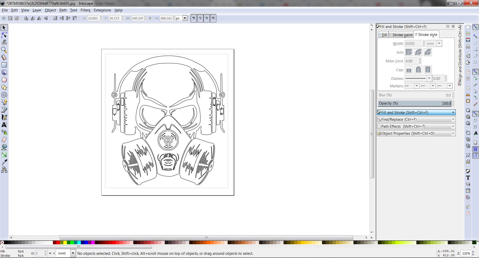
We can use the Path>Trace bitmap tool to get the paths first. Then the fill has to be changed to none.
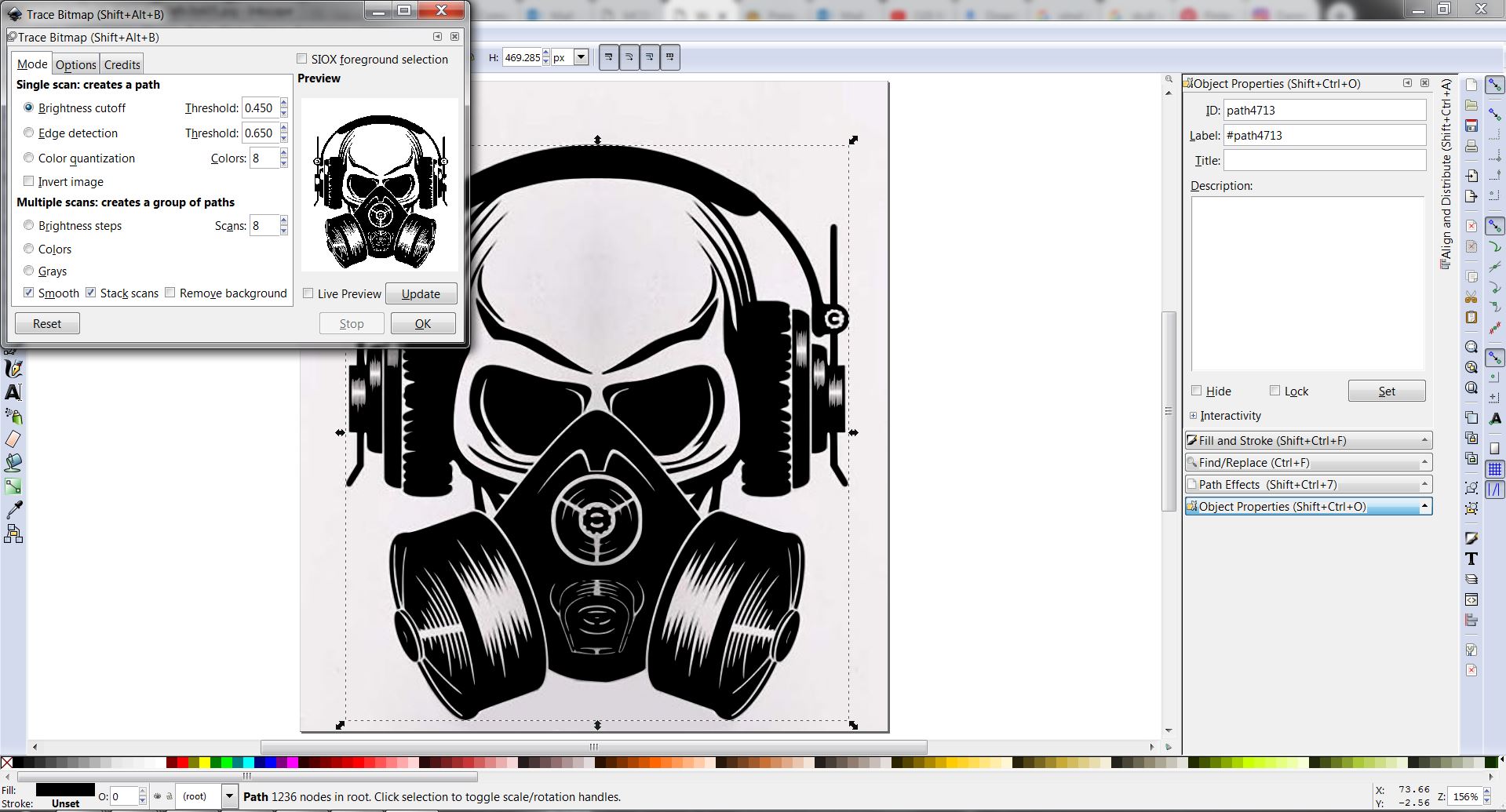
Next using the Edit path nodes tool, the details can be changed accordingly.
Put the Vinyl paper on the designated place after opening the lever. Then after closing the lever, the vinyl cutter has to be turned on. Moreover, note that the pinch rollers must be aligned with the white color grit marks in the machine.
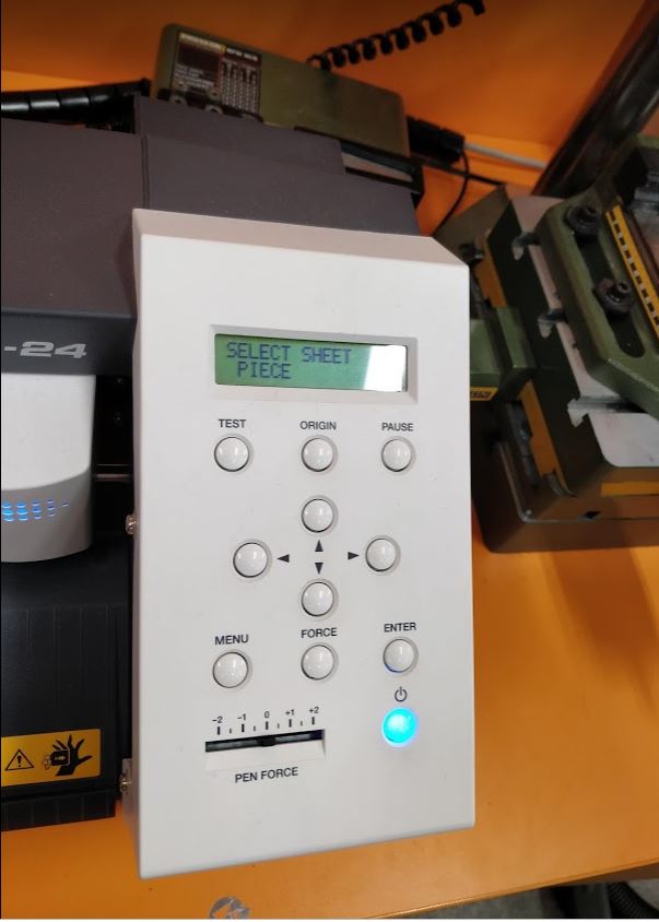
Then we have to choose between Roll (machine assumes that there's a big enough roll), Edge (the machine will look for the edge to start) or Piece options from the menu. Since I have used a small piece I decided to select the piece option. Then after pressing 'ENTER' button the machine it will automatically measure the size of the piece and display it.
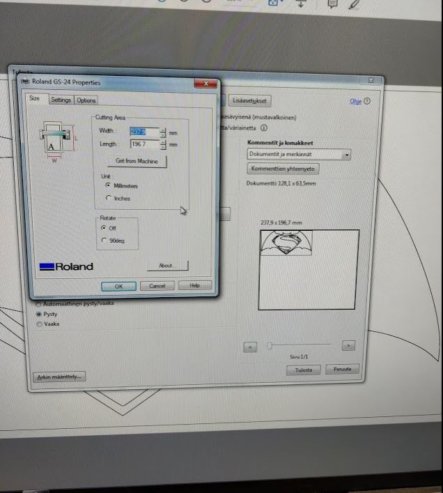
Then, open the design on the PC. Then go to print options. After going to printer options and select the Roland GS24 there will be a menu as the following picture. Then press the button "Get from the machine" since we have to give the correct length and the width for the design.This will measure the width and length of your material and it will give the width and length of the piece of material. Here keeping the width that is given the machine and the length should be changed according to the design. Then after pressing print, the machine will start printing.
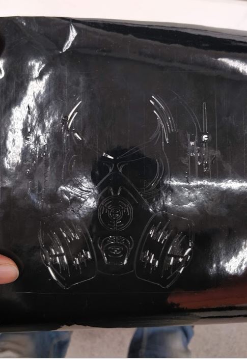
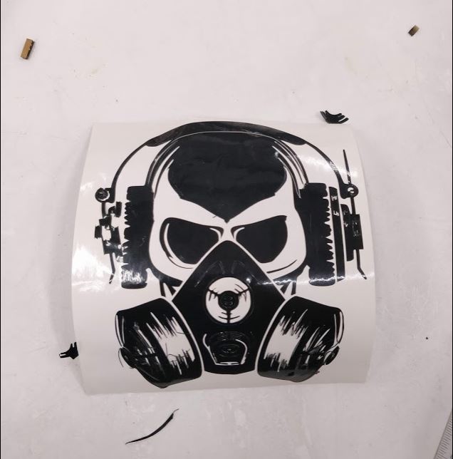
Since my design was too small it was observed that small and detailed parts of the design were pulled out while working. Therefore the final sticker was not as good as expected. The second sticker I printed using the same procedure was more successful than the first one because of fewer details. The line width used is 0.282mm and the force of the pen was used 0. To weed the design I used a tweezer and I did not use any transfer sheet although it would have been much easier.
parametric press fit kit design
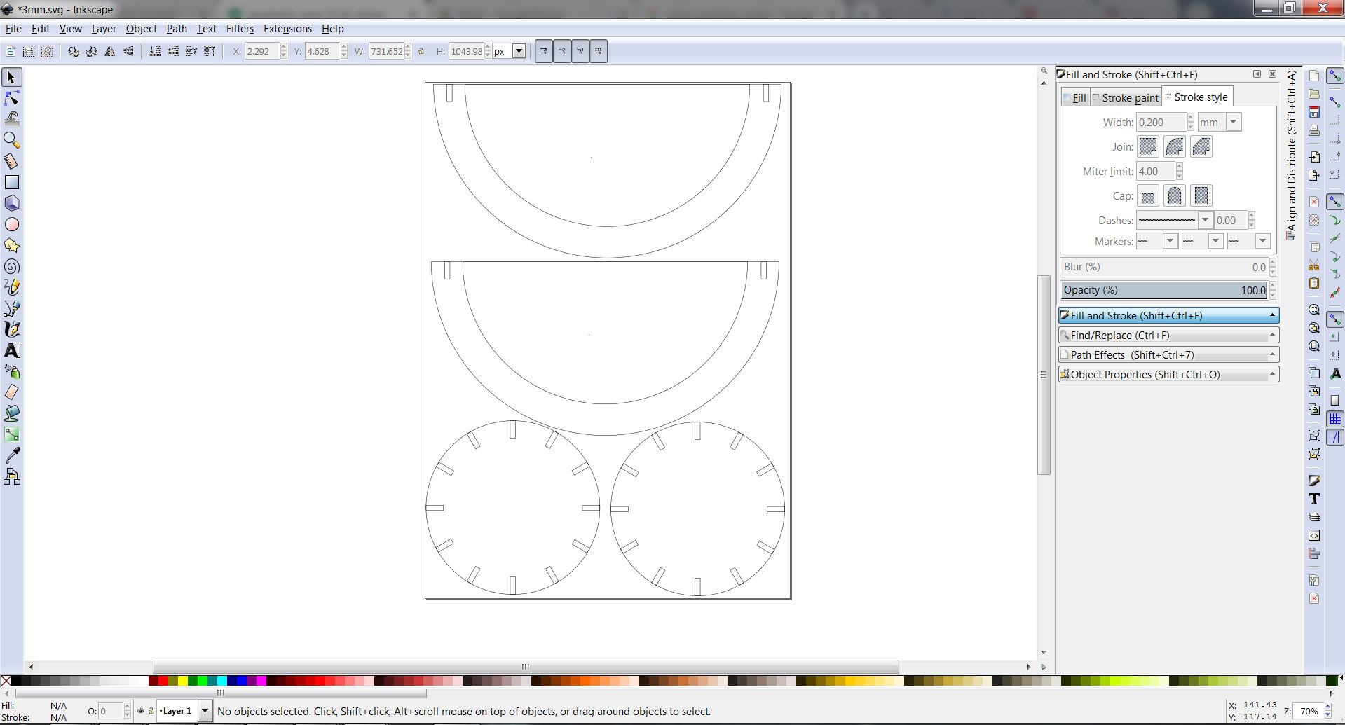
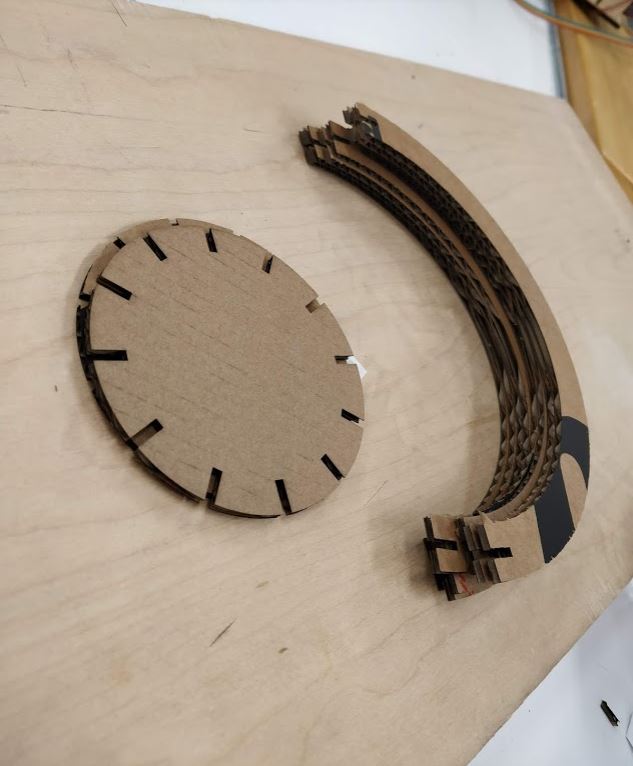
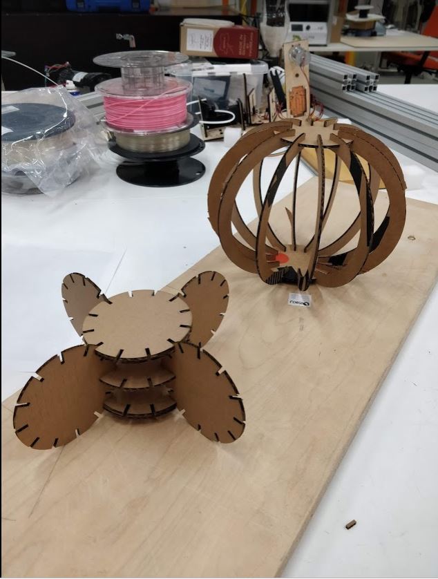
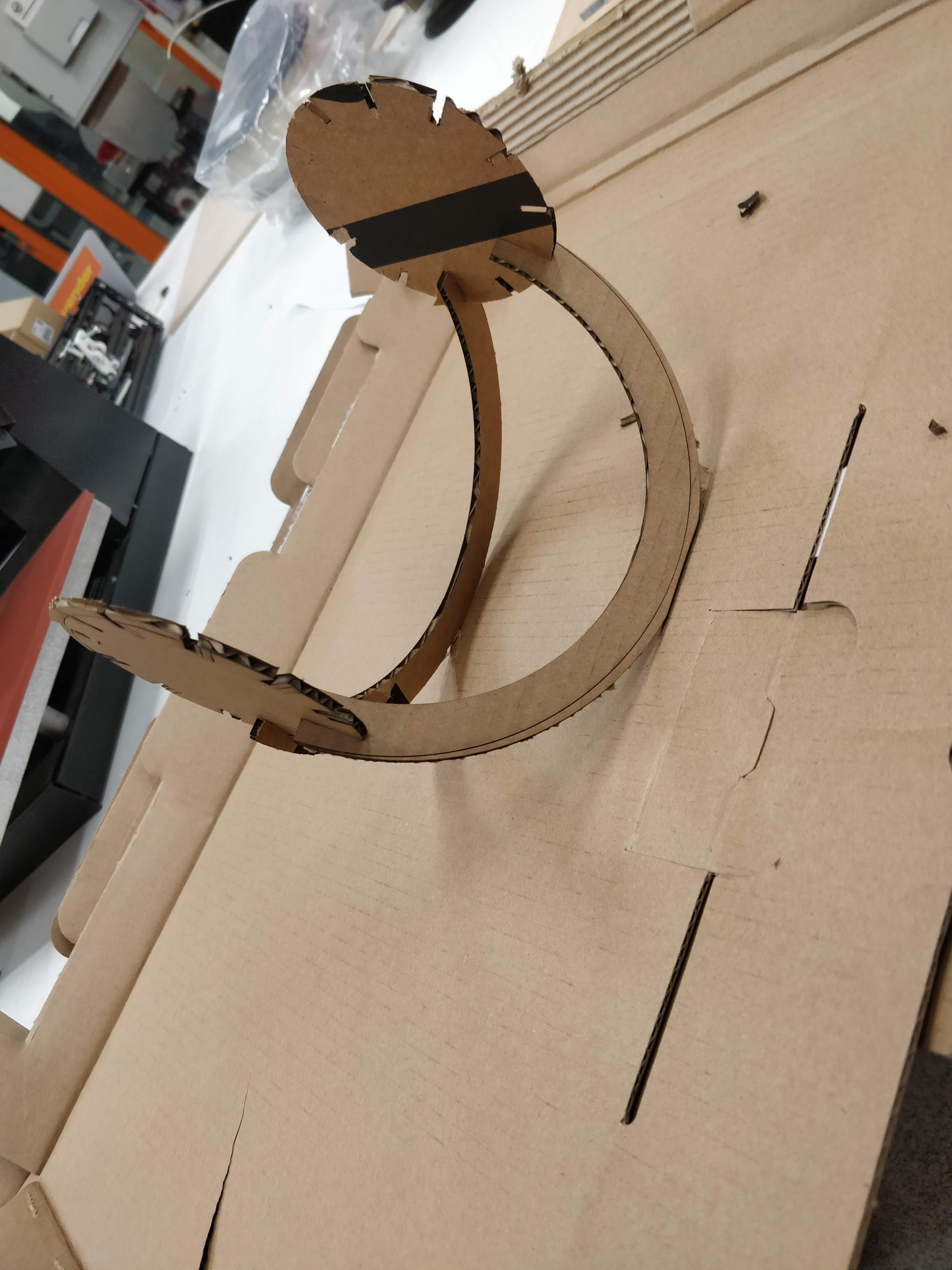
I decided to use cardboard as the material for my individual assignment which is to make a parametric press fit design. I wanted to make a globe which is made my pieces of semi circles holded by a circle. since I had a clear idea about what I was going to make and I'm very familiar with Inkscape software, first, I made the design using Inkscape.
First, select the circle tool and give 0 and 180 values to change dialog box which is on the left top toolbar. Then using this we can make a semi-circle.
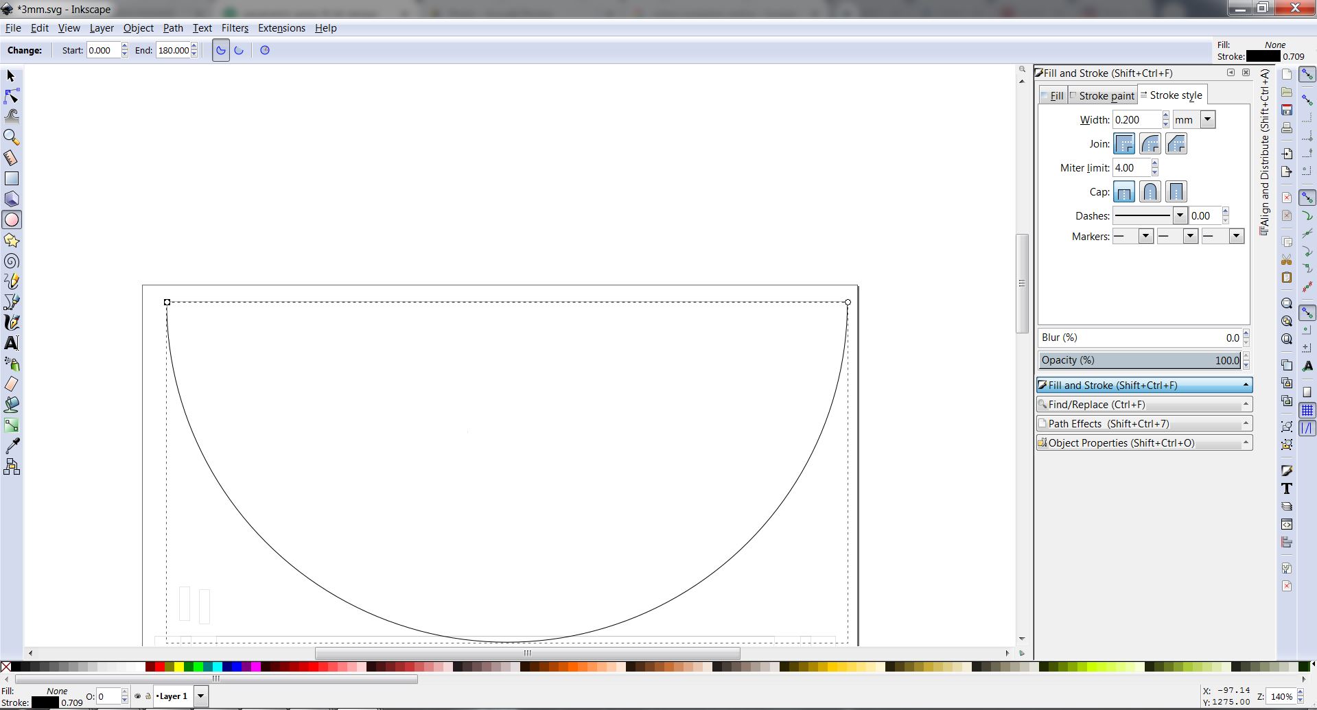
Then I made two semicircles on top of each other with different radius. Since the thickness of the cardboard is 3mm which I was going to make my design I made two cuts with 2.98 mm width. Here I have calculated the value of the width as (material thickness-average kerf). .
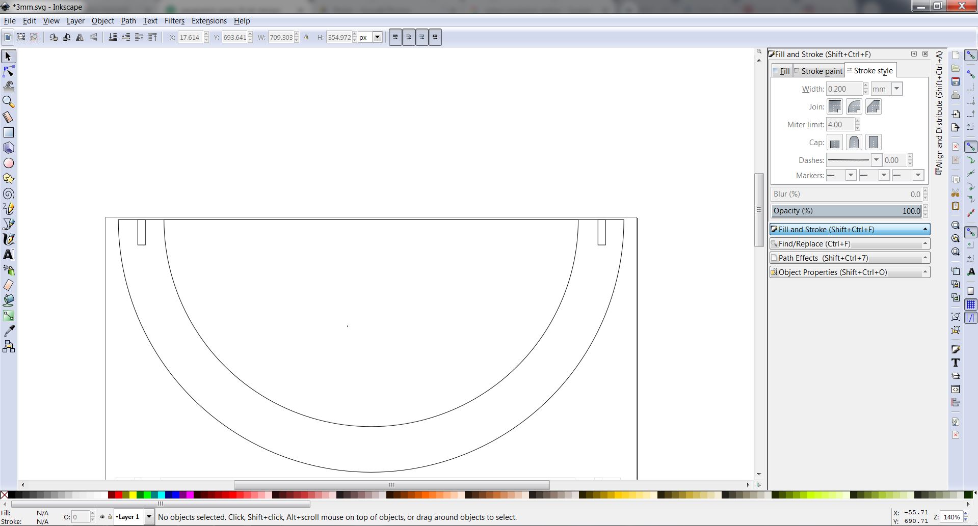
Next, I created a circular part to hold the semi-circles together by making 3.02mm cuts on a circle. Here also I added the value of the kerf to the design. I could rotate these rectangles with the help of CTRL button to snap to right angles.
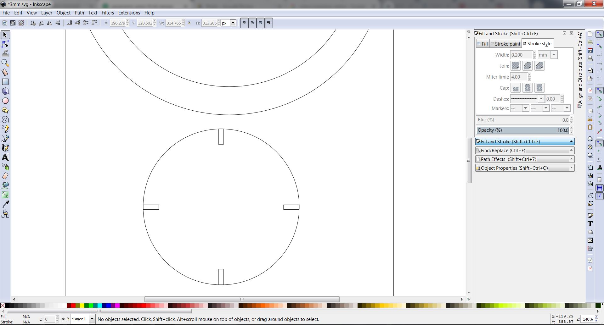
The line width of the shapes was selected as 0.02mm since this is going to be a vector cutting. Finally, finished the design as saving as a pdf.
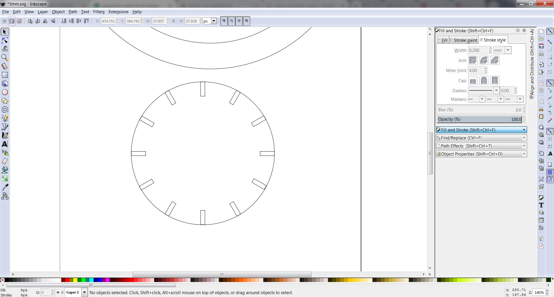
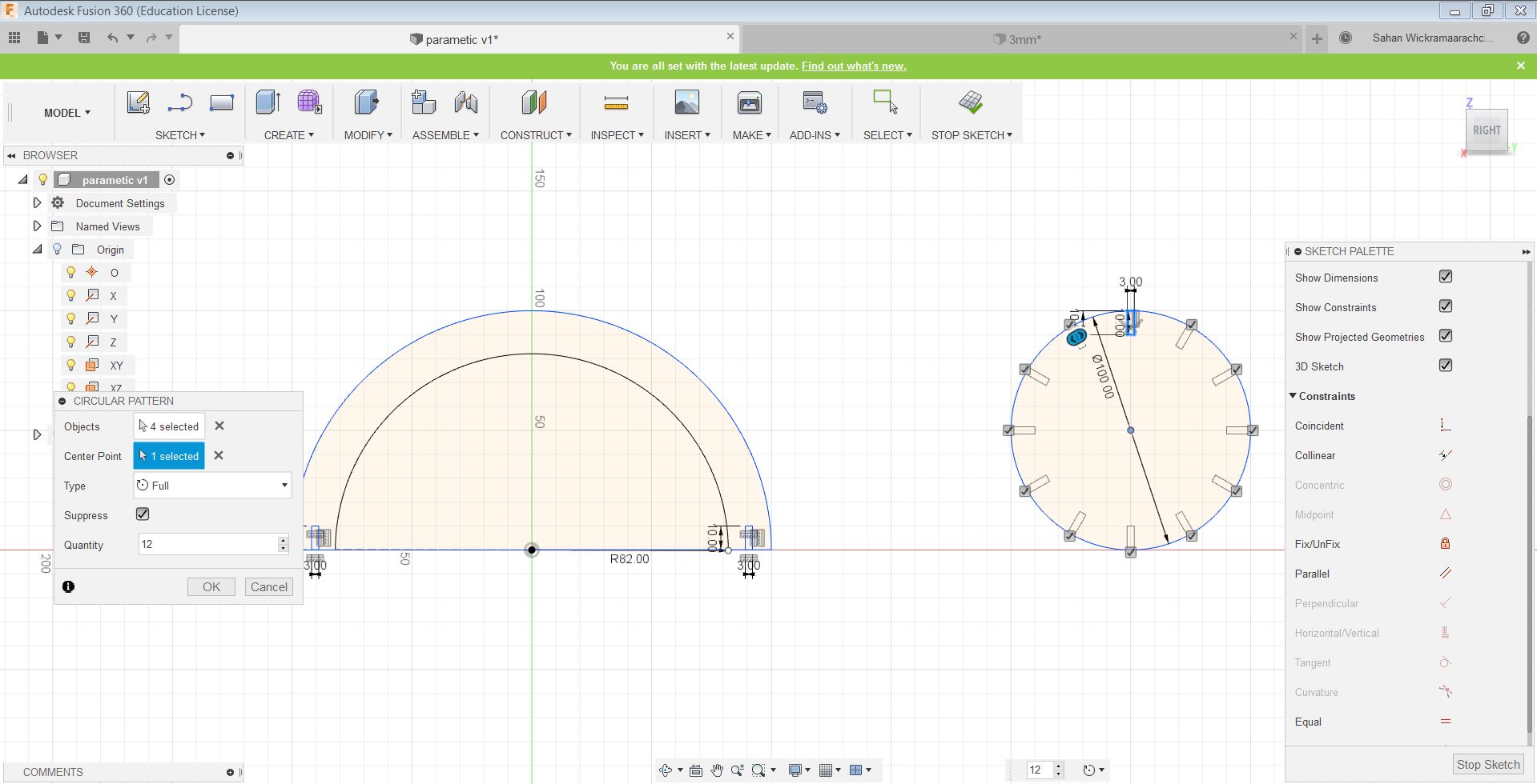
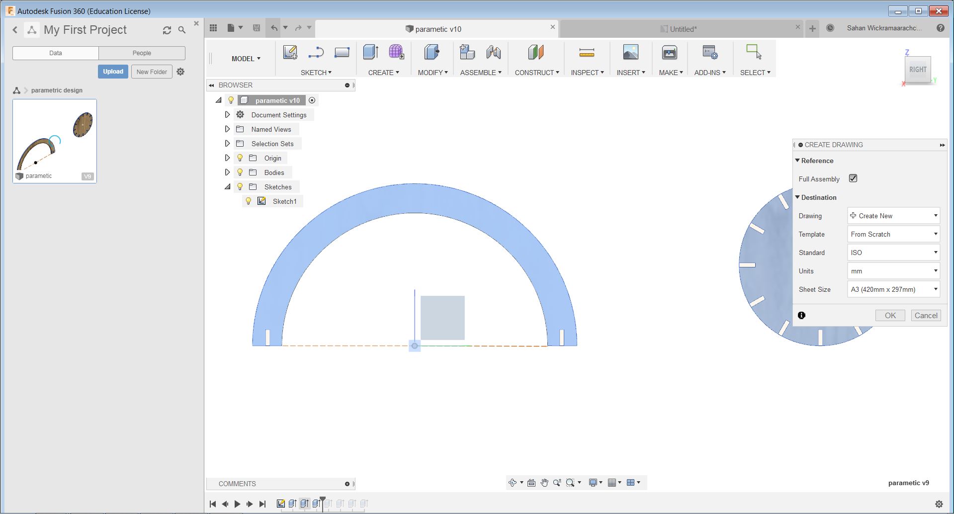
After getting feedback from the Instructor I decided to do the parametric design again on Fusion 360 software. First I created a new file on the fusion 360. Next using Arc tool and Line tools I created a semicircle. Next I created a circle using the circle tool and made a slot using rectangle tool. Next I used circular pattern tool to create all slots around the circle. These all shapes were made with reference to my previous design on Inkspace. After that, I added parameters to the design. In my design, the slot width will has been used as material thickness-kerf.Therefore if I change some parameter the whole design will be changed accordingly.

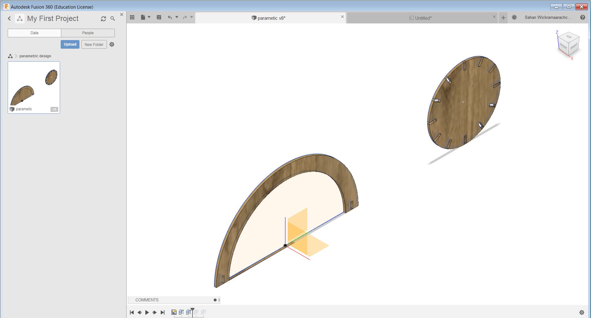
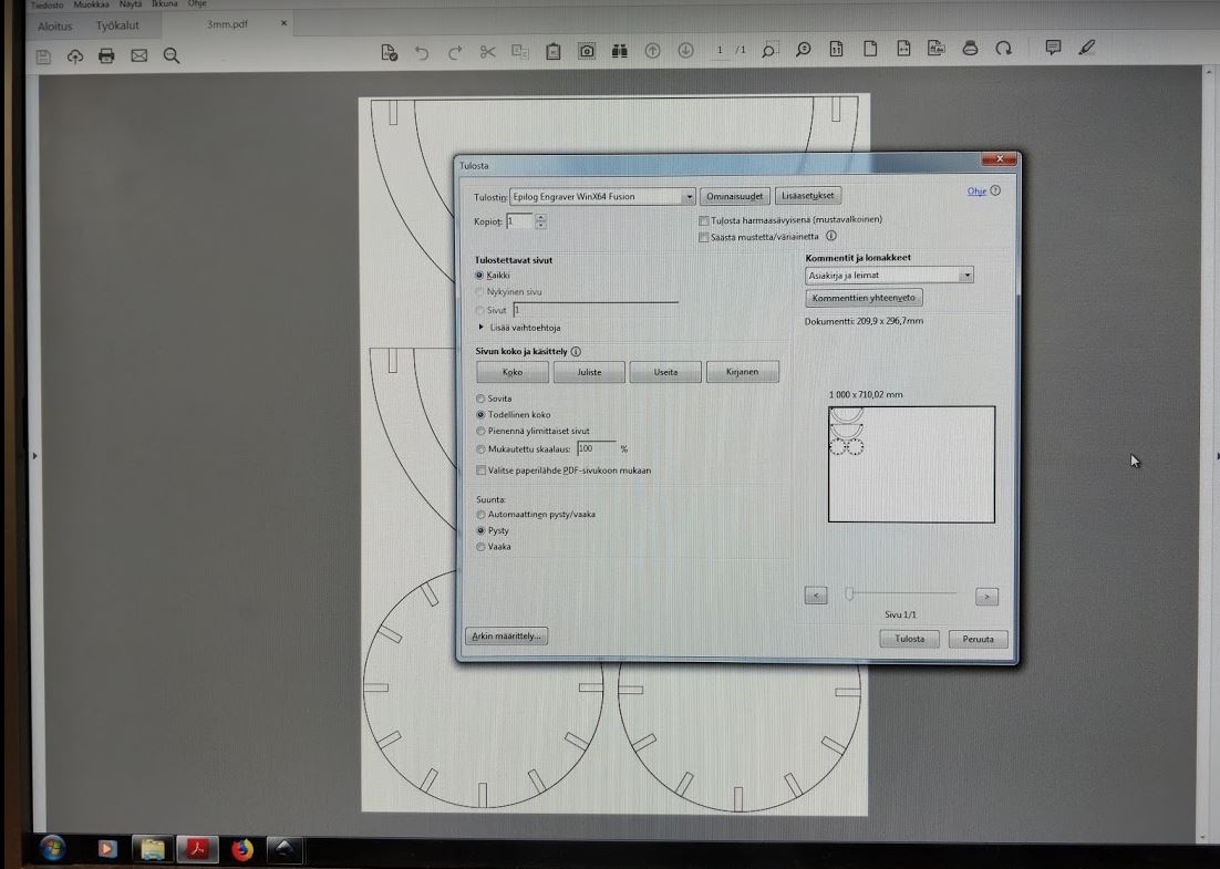
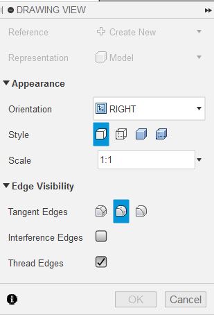
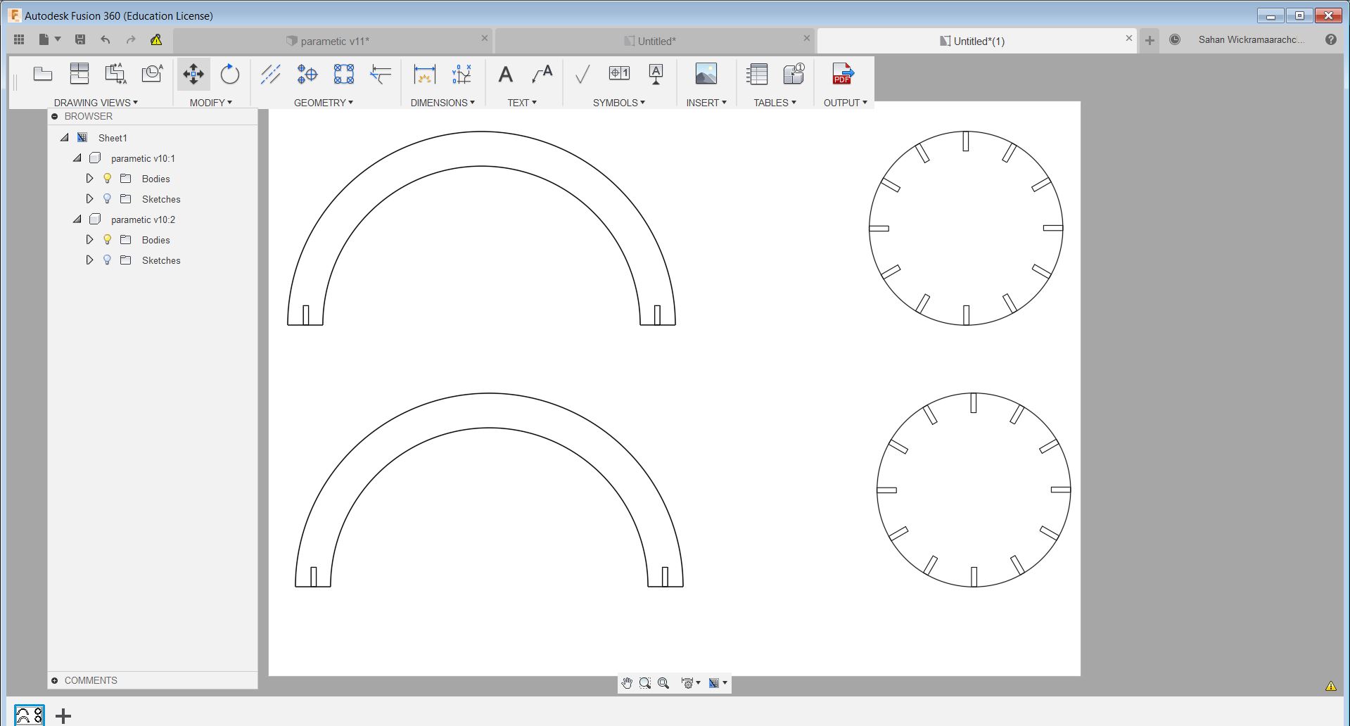
I extruded the sketch 3mm before going to the drawing mode. We can select it MODEL>DRAWING>Drawing from design to prepare the file for printing. From the DRAWING VIEW box change orientation to the correct view according to your design, 'Style' to Visible and Hidden Edges and Scale to 1:1 and click ok. The object can be duplicated by selecting DRAWING VIEWS>Base Drawing. I saved it as a pdf and opened in the computer with the inkscape software next. Then I changed the line width to 0.02mm of the design and saved again. Now its ready to be cut. I have described above the process of laser cutting on this page.
Reflection
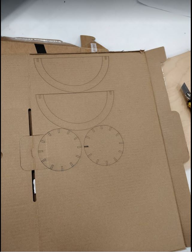
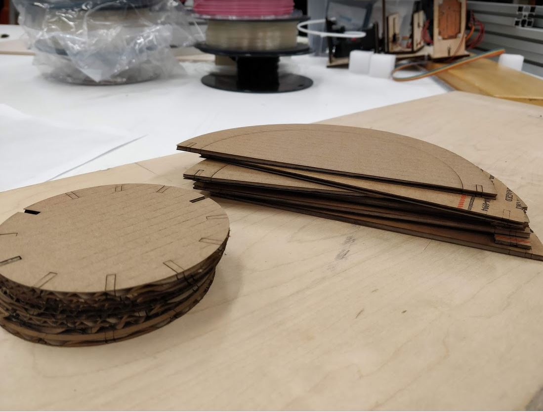
Here after I checked my design later I noticed that some slots had a different value of width due to design inaccuracies but nevertheless the I was able to complete my design with the help of cardboard flexibility. Moreover, making the design on software was challenging since I was not familiar with it. However using the laser cutter got much easier after using it few times. Moreover making the parametric design on Fusion 360 took moretime than thought.
Models files
Vinyl cutter design 1
Vinyl cutter design 2
pdf file for Laser cutting the pressfit design
F3d file for parametric design on fusion 360
STL file for parametric design on fusion 360