Task 14
Networking and communications
In this week, I was given a task to have a group assignment and an individual assignment. The group assignment was to send a message between two projects, and the individual assignment was to design, build, and connect wired or wireless node(s) with network or bus addresses
Group Task
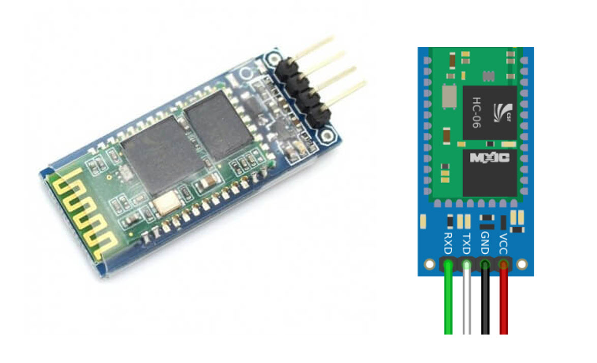
For this week, I started with the Group work. I worked with Alok, Jobin, Sahan, Micheal and Marjo. We used HC-06 Bluetooth Module for the group work. Arduino can communicate with other device via Bluetooth using the module HC-06 (slave). The HC-06 is a class 2 slave Bluetooth module designed for transparent wireless serial communication. Once it is paired to a master Bluetooth device such as PC, smart phones and tablet, its operation becomes transparent to the user. All data received through the serial input is immediately transmitted over the air. When the module receives wireless data, it is sent out through the serial interface exactly at it is received. No user code specific to the Bluetooth module is needed at all in the user microcontroller program.
The module has two modes of operation, Command Mode where we can send AT commands to it and Data Mode where it transmits and receives data to and from another Bluetooth module. By default the device was in Command mode and needs to pair with some device to get it into data mode.
- Below are some features of the Module:
- Bluetooth v2.0+EDR
- 2.4GHz ISM band frequency
- Default baudrate: 9600
- Power supply: 3.6V to 6V DC
- 2.4GHz ISM band frequency
Bluetooth Module HC-06 configuration with Arduino
The Bluetooth module HC-06 has 4 pins, 2 for power and 2 to establish connection:
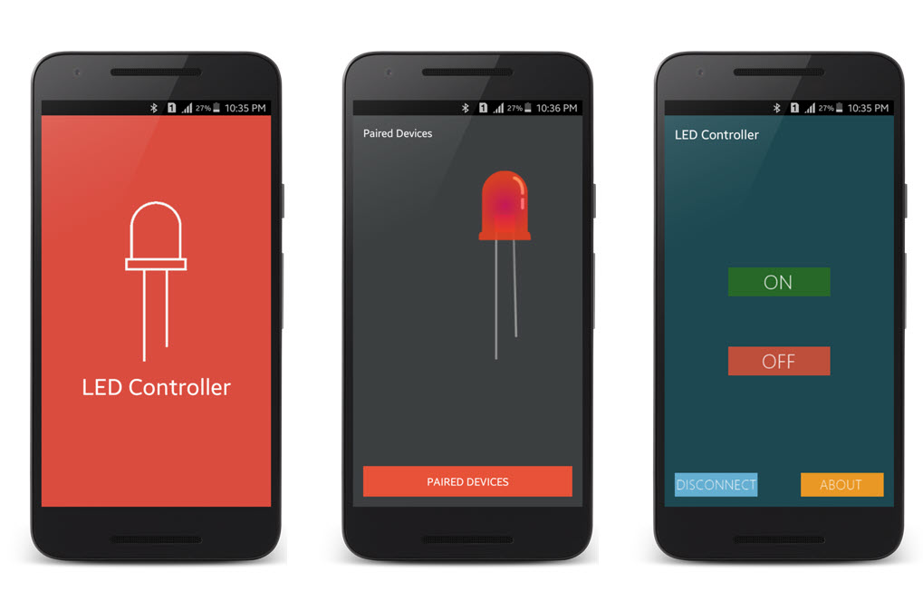
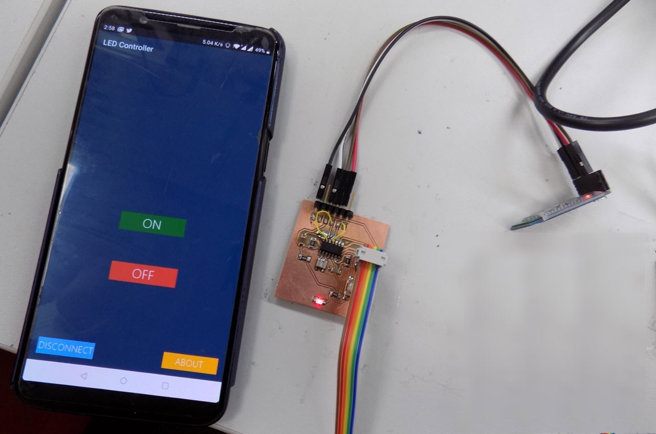
We utilized this turorial for configuration of boards and the Bluetooth Module. Initially the idea was to blink an LED on any of our Week 07 Echo Hello boards thereby we tried to connect one board with the Bluetooth module. Obviously HC-06(Slave) module will be connected to the Master Module (i.e Mobile Bluetooth), thereby to interact with the Blutooth Module HC-06, Mayoogh-Girish-LED-Controller Application was downloaded and installed on the Mobile.
- General Working of HC-06:
The code was modified by defining the TX and RX Pins to use, The Ignite Inovates turorial amd Aranacorp Tutorial was also helpful in this regard. Below is the Modified Code for the Single Node
Single Node (LED ON and OFF):
 #include < SoftwareSerial.h >   // To define the pins of the serial port
#define txPin 0     // PA0(MISO) transmit signal to the bridge
#define rxPin 1     // PA1(SCK) recieves signal from bridge

SoftwareSerial mySerial(rxPin,txPin);

char Incoming_value = 0;                //Variable for storing Incoming_value
void setup()
{
  mySerial.begin(9600);         //Sets the data rate in bits per second (baud) for serial data transmission
  pinMode(txPin, INPUT);   //default tx as input
  pinMode(8, OUTPUT);        //Sets digital pin 13 as output pin
}
void loop()
{
  if(mySerial.available() > 0)
  {
    Incoming_value = mySerial.read();      //Read the incoming data and store it into variable Incoming_value
    mySerial.print(Incoming_value);        //Print Value of Incoming_value in Serial monitor
    mySerial.print("\n");        //New line
    if(Incoming_value == '1')            //Checks whether value of Incoming_value is equal to 1
      digitalWrite(8, HIGH);  //If value is 1 then LED turns ON
    else if(Incoming_value == '0')       //Checks whether value of Incoming_value is equal to 0
      digitalWrite(8, LOW);   //If value is 0 then LED turns OFF
  }
}
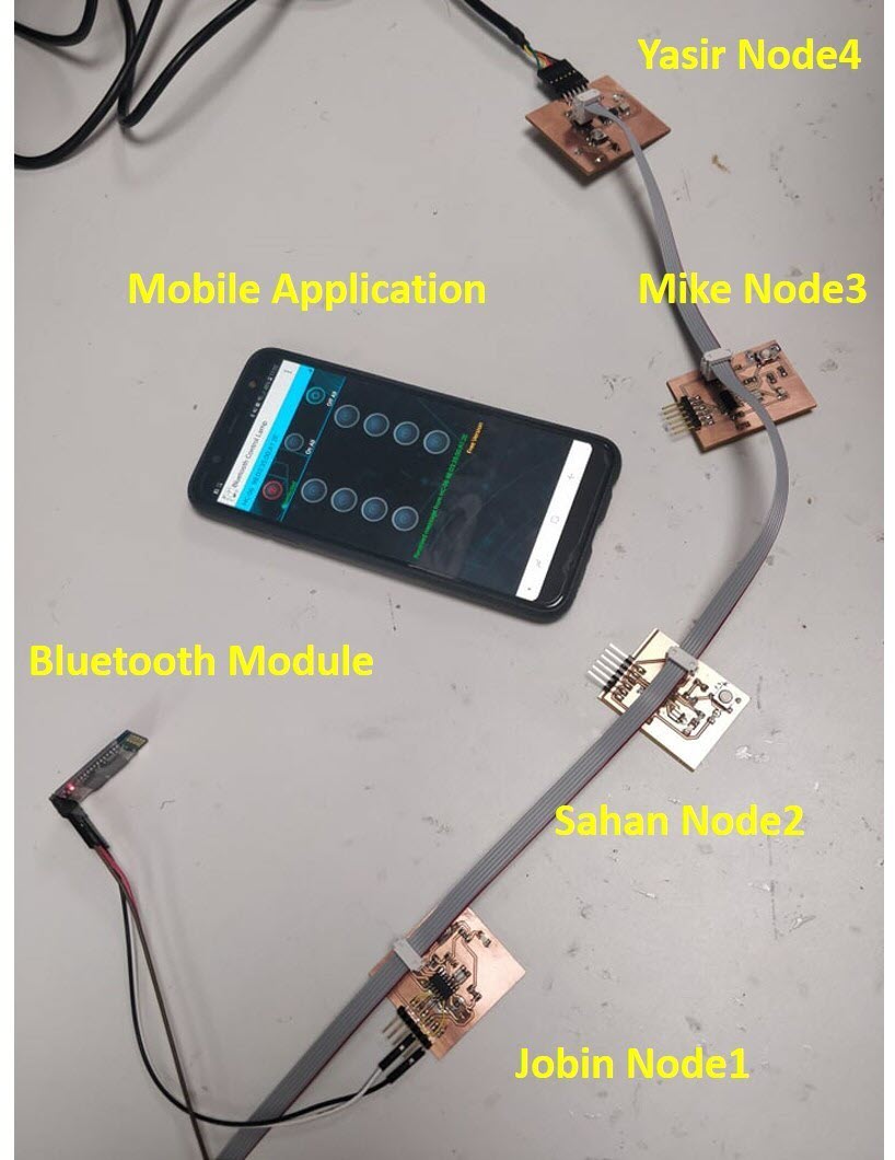
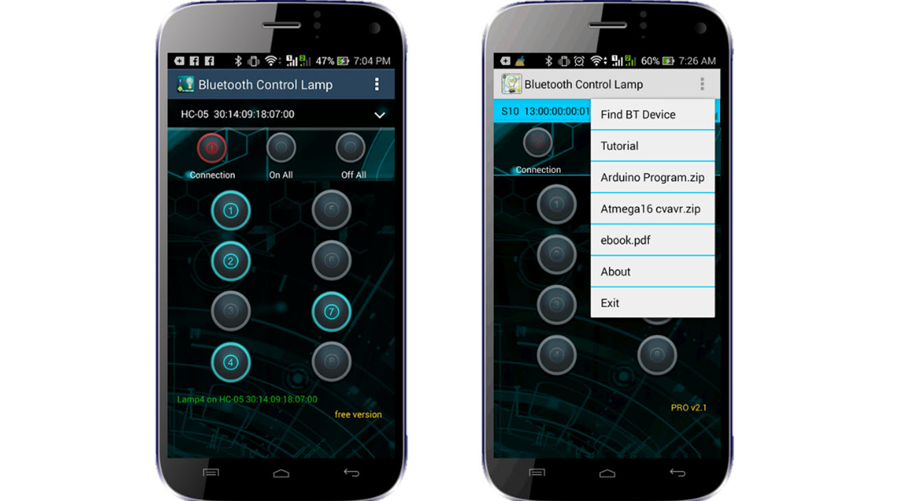
After the success with the implementation of the code on one board, we advance to implement it on muliple boards thereby using the boards of me, Sahan, Micheal and Jobin. This time, we required a new application for our mobile that can assist us to control multiple Nodes thereby we downloaded Bluetooth Controller 8 Lamp from Google Playstore.The code almost remained the same, we added the If..else condition to provide addressing to the nodes to respond different with respect to the coming Incoming value. Thereby each node is addressed differently and the LED turns ON and OFF at that Node.
Multiple Nodes (LED ON and OFF) | One Node Addressing Example:
 #include < SoftwareSerial.h >
#define txPin 0     // PA0(MISO) transmit signal to the bridge
#define rxPin 1     // PA1(SCK) recieves signal from bridge

SoftwareSerial mySerial(rxPin,txPin);

char Incoming_value = 0;                //Variable for storing Incoming_value
void setup()
{
  mySerial.begin(9600);         //Sets the data rate in bits per second (baud) for serial data transmission
  pinMode(txPin, INPUT);   //default tx as input
  pinMode(8, OUTPUT);        //Sets digital pin 8 as output pin
  pinMode(4, OUTPUT);        //Sets digital pin 4 as output pin
}
void loop()
{
  if(mySerial.available() > 0)
  {
    Incoming_value = mySerial.read();      //Read the incoming data and store it into variable Incoming_value
    mySerial.print(Incoming_value);        //Print Value of Incoming_value in Serial monitor
    mySerial.print("\n");        //New line
    if(Incoming_value == '1')            //Checks whether value of Incoming_value is equal to 1 (Addressing)
    {  digitalWrite(8, HIGH);  //If value is 1 then LED turns ON
      digitalWrite(4, HIGH);  //If value is 1 the Tx to Sahan Node
    }
    else if(Incoming_value == 'A')       //Checks whether value of Incoming_value is equal to 0 (Addressing)
     { digitalWrite(8, LOW);   //If value is 0 then LED turns OFF
      digitalWrite(4, LOW);  //If value is 0 the Tx to Sahan Node
     }
  }

}
Individual Task
For thie Individual Task, I used the same bluetooth module HC-06 since I had a lot of Information about it and I already understood how to perform the coding. This time I used the boards, I made on Week 07 Echo Hello as Node-1 and Week 12 output week as Node-2 board. In the Output week I used the stepper motor as my output device thereby I thought to run the motor by giving the command from my mobile application. I used the same Bluetooth Controller 8 Lamp application. Below is the Code for Node1 and Node2
Node 1 : (LED ON and OFF)
 #include < SoftwareSerial.h >
#define txPin 4     // PA0(MISO) transmit signal to the bridge
#define rxPin 5     // PA1(SCK) recieves signal from bridge

SoftwareSerial mySerial(rxPin,txPin);

char Incoming_value = 0;                //Variable for storing Incoming_value
void setup()
{
  mySerial.begin(9600);         //Sets the data rate in bits per second (baud) for serial data transmission
  pinMode(txPin, INPUT);   //default tx as input
  pinMode(8, OUTPUT);        //Sets digital pin 8 as output pin
  //pinMode(4, OUTPUT);        //Sets digital pin 4 as output pin
}
void loop()
{
  if(mySerial.available() > 0)
  {
    Incoming_value = mySerial.read();      //Read the incoming data and store it into variable Incoming_value
    mySerial.print(Incoming_value);        //Print Value of Incoming_value in Serial monitor
    mySerial.print("\n");        //New line
    if(Incoming_value == '1')            //Checks whether value of Incoming_value is equal to 1
    {  digitalWrite(8, HIGH);  //If value is 1 then LED turns ON
      //digitalWrite(4, HIGH);  //If value is 1 the Tx to Sahan Node
    }
    else if(Incoming_value == 'A')       //Checks whether value of Incoming_value is equal to A
     { digitalWrite(8, LOW);   //If value is 0 then LED turns OFF
      //digitalWrite(4, LOW);  //If value is 0 the Tx to Sahan Node
     }

      else if(Incoming_value == '9')            //Checks whether value of Incoming_value is equal to 9
    {  digitalWrite(8, HIGH);  //If value is 1 then LED turns ON

    }
    else if(Incoming_value == 'I')       //Checks whether value of Incoming_value is equal to I
     { digitalWrite(8, LOW);   //If value is 0 then LED turns OFF

     }
  }

}
Node 2 : (Stepper Control)
  #include < SoftwareSerial.h >
#define txPin 4     // PA0(MISO) transmit signal to the bridge
#define rxPin 5     // PA1(SCK) recieves signal from bridge

SoftwareSerial mySerial(rxPin,txPin);

const int stepPin = 3;
const int dirPin = 2;

char Incoming_value = 0;                //Variable for storing Incoming_value
void setup()
{
  mySerial.begin(9600);         //Sets the data rate in bits per second (baud) for serial data transmission
  pinMode(txPin, INPUT);   //default tx as input
  pinMode(stepPin,OUTPUT);
  pinMode(dirPin,OUTPUT);

}
void loop()
{
  if(mySerial.available() > 0)
  {
    Incoming_value = mySerial.read();      //Read the incoming data and store it into variable Incoming_value
    mySerial.print(Incoming_value);        //Print Value of Incoming_value in Serial monitor
    mySerial.print("\n");        //New line
    if(Incoming_value == '2')            //Checks whether value of Incoming_value is equal to 2
    {
      digitalWrite(dirPin,LOW); // Enables the motor to move in a particular direction
  // Makes 200 pulses for making one full cycle rotation
  for(int x = 0; x < 1000; x++) {
    digitalWrite(stepPin,HIGH);

    delay(1);  // ms
    digitalWrite(stepPin,LOW);

    delay(1);

    if(Incoming_value == 'B')       //Checks whether value of Incoming_value is equal to B
     { digitalWrite(dirPin,LOW);   //If value is B then set dir low and Step low
       digitalWrite(stepPin,LOW);
     }

     else if(Incoming_value == 'I')       //Checks whether value of Incoming_value is equal to 0
     { digitalWrite(dirPin,LOW);    //If value is I then set dir low and Step low
       digitalWrite(stepPin,LOW);

     }

  }
    }

           else if(Incoming_value == '9')            //Checks whether value of Incoming_value is equal to 1
    {
      digitalWrite(dirPin,LOW); // Enables the motor to move in a particular direction
  // Makes 200 pulses for making one full cycle rotation
  for(int x = 0; x < 1000; x++) {
    digitalWrite(stepPin,HIGH);

    delay(1);  // ms
    digitalWrite(stepPin,LOW);

    delay(1);

  if(Incoming_value == 'I')       //Checks whether value of Incoming_value is equal to 0
     { digitalWrite(dirPin,LOW);    //If value is I then set dir low and Step low
       digitalWrite(stepPin,LOW);

     }

  }
    }

  }

}
Resources Utilized
- I utilized these resources for this task:
- Arduino IDE
- Mayoogh-Girish-LED-Controller Application
- Bluetooth Controller 8 Lamp Application