3D Pieces
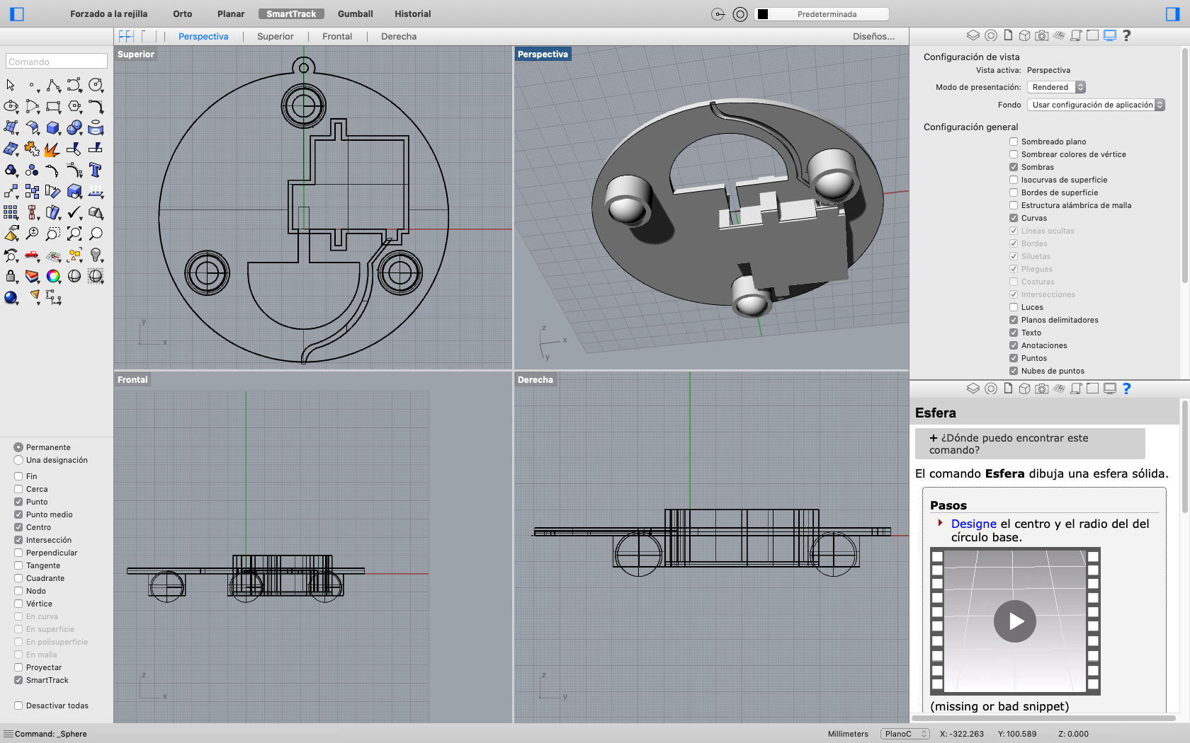
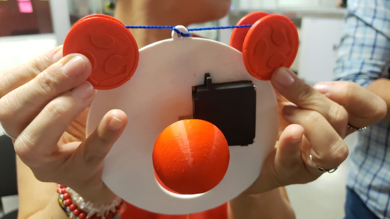
Three 3D pieces were deseigned and printed: 1. The center piece to move around the board, a ball to go up and down to move the fabric and the piece that will be controlled by the motors and that moves the center piece.
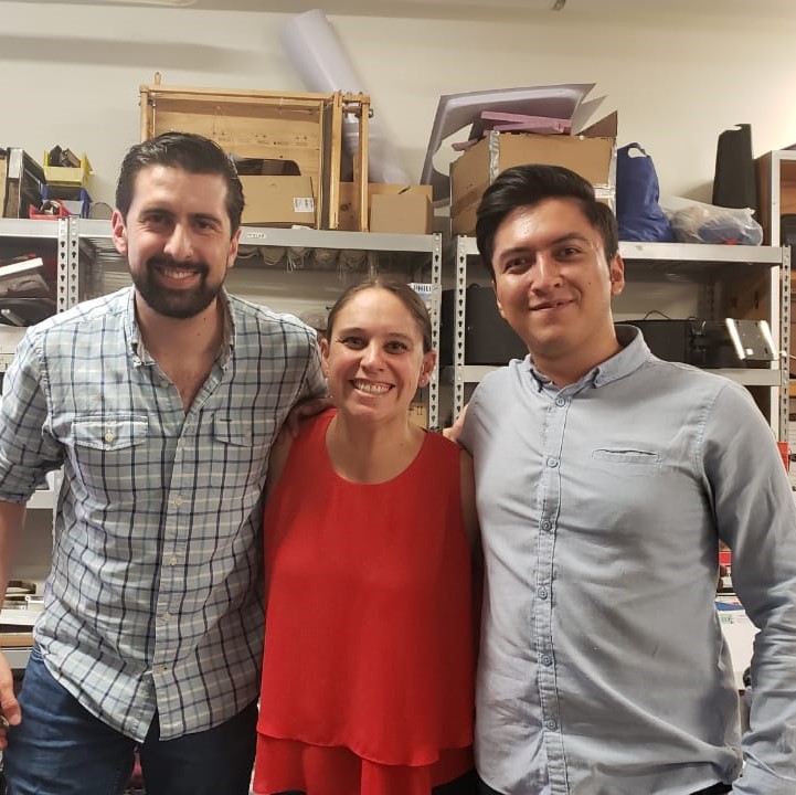
Group Activity
Machine Design
Group Assignment
Instructions: Design a machine that includes mechanism+actuation+automation, build the mechanical parts and operate it manually and document the group project and your individual contribution.
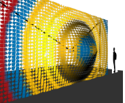
Concept: Design and build a machine for conceptual art. It has a center piece that moves around following the closest person's face through image recognition. In a second phase it will communicate with a program that projects an image onto a white surface to create patterns that interact with people passsing by.
Integer eu ante ornare amet commetus vestibulum blandit integer in curae ac faucibus integer non. Adipiscing cubilia elementum integer lorem ipsum dolor sit amet.
Integrate, in a team effort, some of the concepts learned so far in the Fab Acadaemy to create a Machine. In our case we are developing a conceptual art machine incorporating image recognition to implement movement.
Three 3D pieces were deseigned and printed: 1. The center piece to move around the board, a ball to go up and down to move the fabric and the piece that will be controlled by the motors and that moves the center piece.
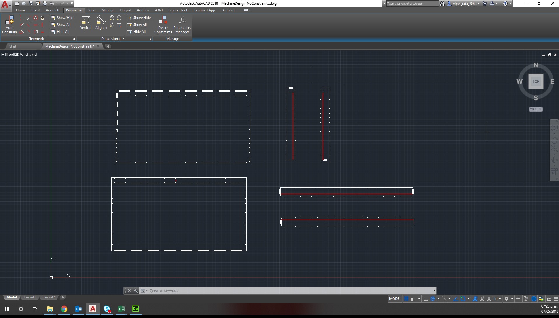
A box using press fit concepts was designed. It will be to be cutted using a CNC Router. It is to hold every single component, cover the electronics and to serve as a functional frame for the whole thing.
Validate the mechanism through a manual test, to ratify that our theory was correct. We included two tests, one without the fabric and another one with the fabric.
Validate the mechanism through a manual test, to ratify that our theory was correct. We included two tests, one without the fabric and another one with the fabric.
We designed an arduino and the step motor drivers, engraved, cut, and soldered the final PCBs to use them in the CNC.
We created software to program the arduino and drivers, we are using the GRBL software to control the motors from a laptop.
Original costs in mexican pesos converted to USD at an average rate of 20 MXP per USD.
Total costs for materials: $ 181.95 USD
| Material | Quantity | Total Cost |
|---|---|---|
| MDF 15 mm | 4 | $ 129.00 |
| Fabric | 2.5 sqm | $ 7.50 |
| Velcro | 4.5 m | $ 9.95 |
| Nema 17 motor | 2 | $ 30.80 |
| Servo motor MG995 | 1 | $ 4.70 |
Axis X and axis Y are provided by the motors (in the mechanical test by our hands moving the thread). The Z axis will be provided by the ball tip going up and down according to people getting near and going far away from the conceptual art piece.
To cover all of the mechanism a box and a frame were needed, we started with a basic idea on paper as a very low fidelity prototype to define where all of the components would be. After reviewing that concept we reached the conclusion that if anything went wrong with the electronic components qe would not be able to reach it. The first approach to solving te problem was creating a door on the back, but that resulted in a difficult setting since its a large frame that is designed to be hanged high, the final soluction was to leave the components on top hidden by the frame within the space between the motors.
Mechanical operation concept consists of a central piece composed by a central panel, mechanical actuator and a ball tip. This central piece is held by two ropes that are rolled up on two reels at the top. For the mechanical test, we held the ropes and then we rolled it up manually to get our desired position. The reels will be attached to stepper motor located in the upper corners of the frame.
We designed an arduino and the two step motor drivers (x & y) to be connected to a power supply of 12V, after several tests we discovered that the serbo that controls Z needs a differente power supply, specifically a 5V, we solved it (for this presentation) with an arudino connected by usb to a computer to guarantee the power supply.
After several tests including a mechanical, a concept and an electronic test we generated a functional test with all components integrated.