Week 6
Feb 20. 3D Scanning and Printing
Group Assignment
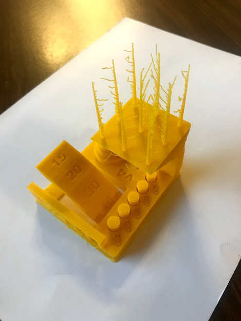
Test design rules for the 3D printer to be used. We tested three an ultimaker, a rostock and a syndoh to define which one to used in each assignment.
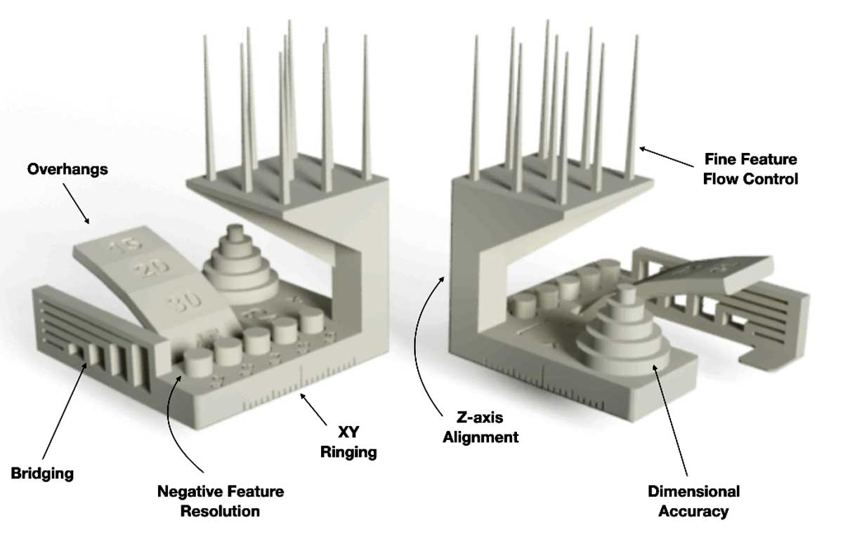
3D Test model
Choose a 3D Test Model to print.
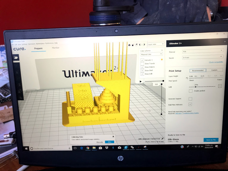
SW Ultimaker Test
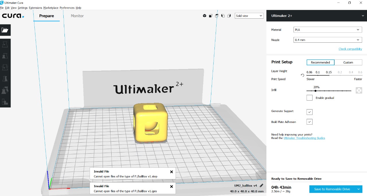
We reviewed the piece to be printed in the software prior to printing.
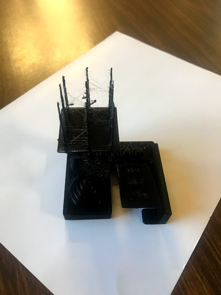
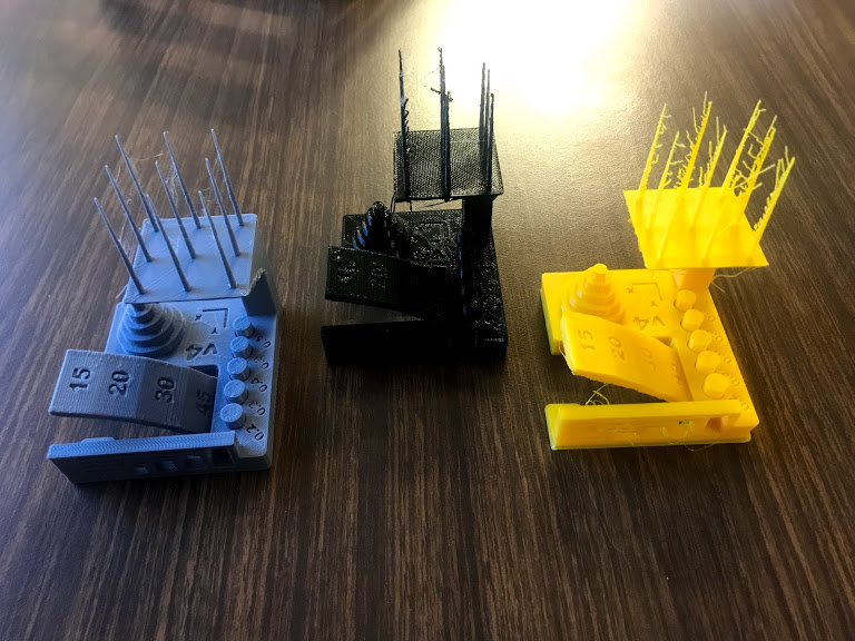
Rostock/h4>
Great for angles.
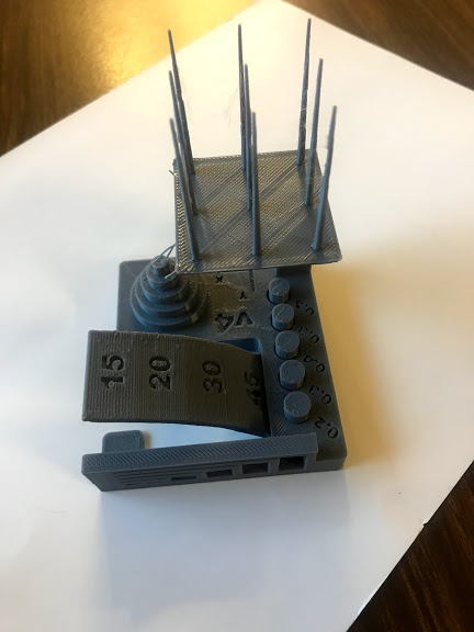
Syndoh
Great for long defined vertical lines.
Ultimaker
Best definition, not great at angles or vertical lines.
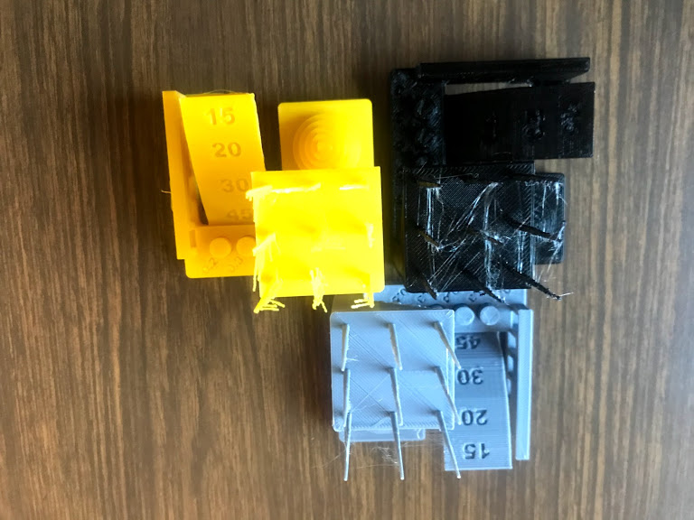
Top View
Syndoh appears the best from the top with definition of vertical lines.
Bottom View
The best quality inside was the Rostock, angles are great with this printer.
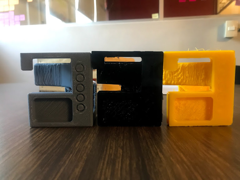
Side View
The best overall is the syndoh.
Instructions
- Look for a test model and download from Internet
- Guarantee is a small enough piece that it will print within a small am ouont of time (took 4 hours each)
- Open in the program for 3D printing
- The parameters used for all printers were. layer height 0.15 and Fill 25%
- Open in 3D printer
- Press start
- Wait until ready
- Eliminate any excess material from the piece
- Repeat with Rostock and Syndoh
- Compare pieces
- I decided to print all of my pieces in the ultimaker despite Syndoh being the best quality overall becauase I did not need to print any angles or vertical lines.
Individual Assignment
3D scan an object with different techniques and optionally print it. I used three different techniques, laser arm scan (Romer), white lighting scanning (Shining 3D) and photometrics (Qlone for iPhone).
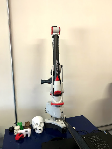
Romer
Scanner used to test the scan by points technique.
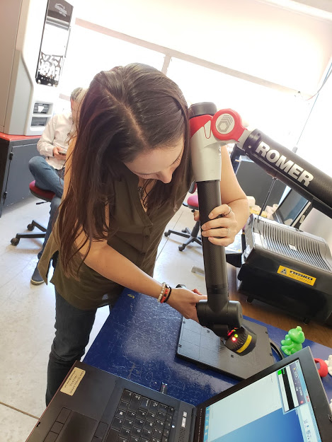
Scanning
Scanning with this technique is by far the most difficult one, you need to cover all surfaces several times.
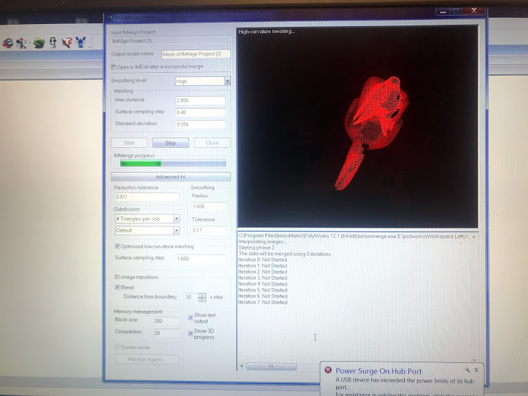
Scan Points
Point map created by the scanner software.
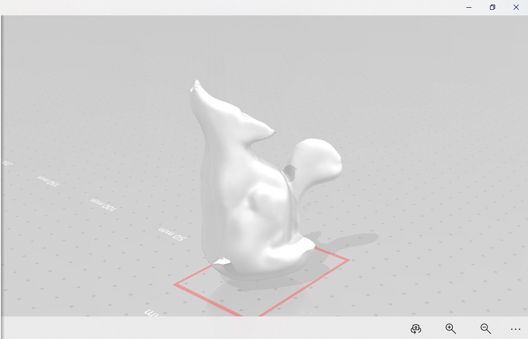
Final Result (arm)
The final result from the romer was imported into GeoMagic and this was my end result (not proud).
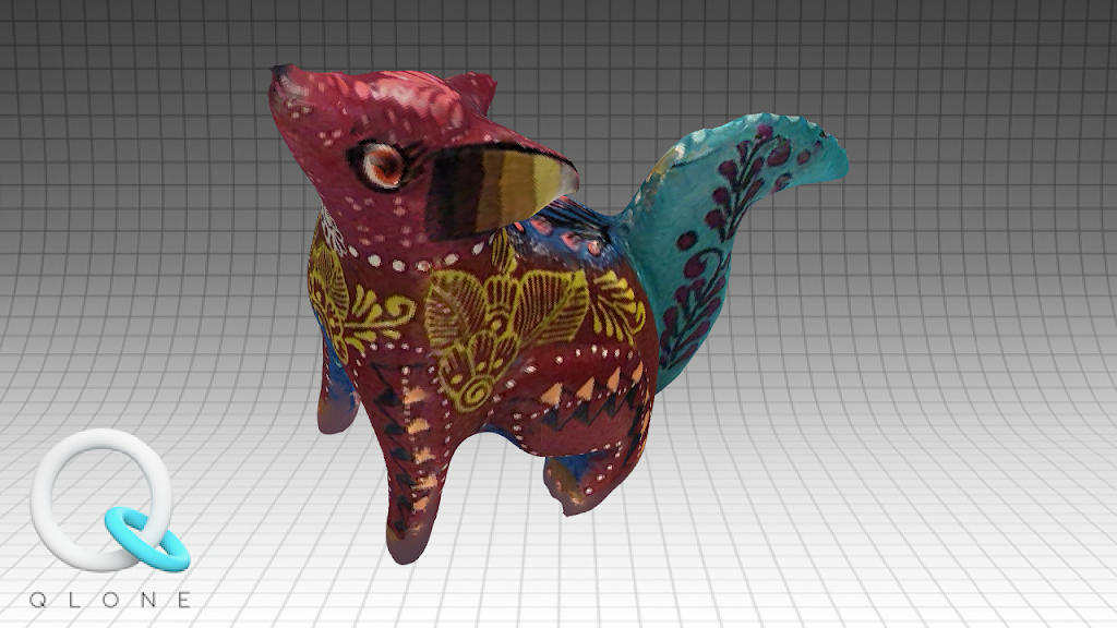
Qlone Scan
Software for iPhone that uses telemetrics.
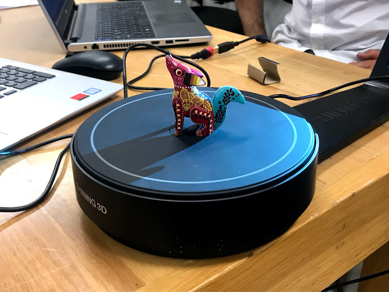
Scanner
Piece to be scanned on scanning table
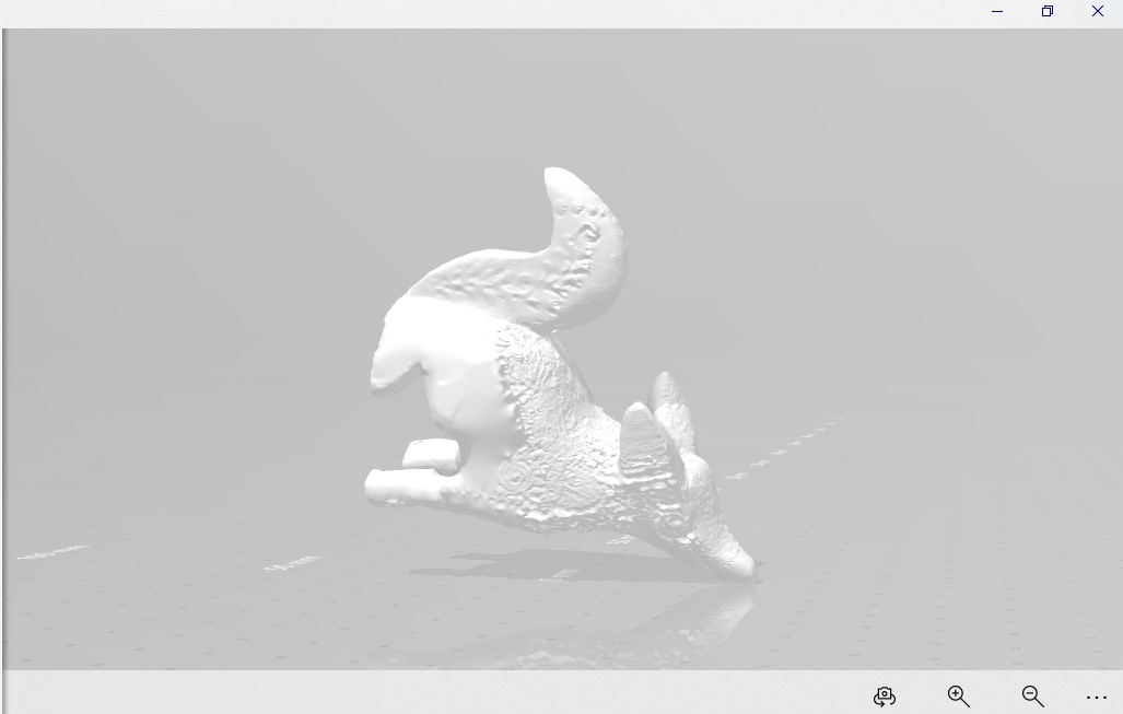
Final Mesh
The mesh is created effortlessly and just touched up in Mesh Mixer
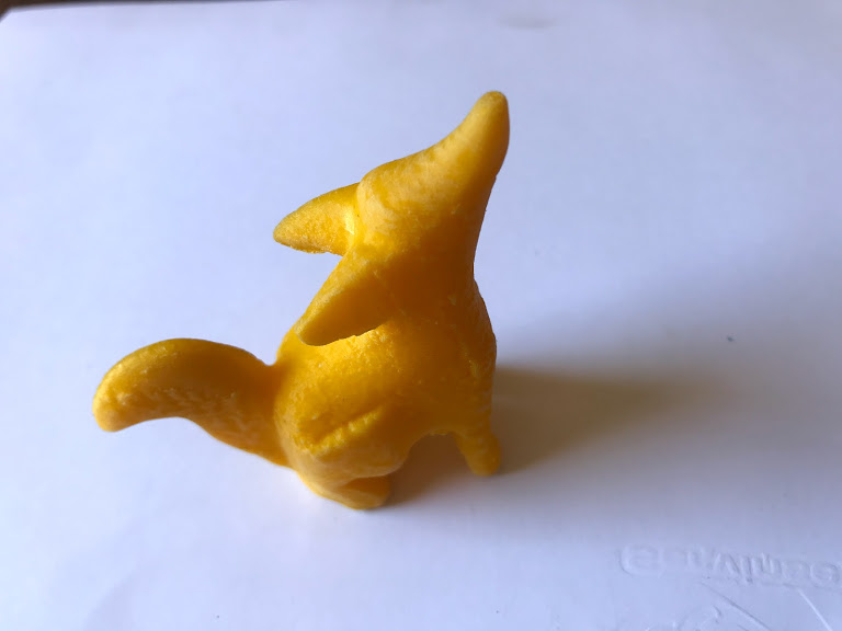
Printed piece
The lightining scanner piece was printed.
Side by Side
Side by side comparison is pretty good, the texture was recognized from the painting in the original piece.

Mirror
Mirror images, the original piece and the new printed one.
Instructions Romer
- Start arm and connect to the computer
- Start software and open scanning mode
- Start moving the laser scan all around the piece
- Continuosly check that the piece is being formed in the computer software
- Continue scanning until th efigure is recognizable
- Save the final result as a txt with coordenates
- Open txt fil in GeoMagic
- Close mesh as good as possible
- Define if you are going to priint the file, if yes export to .stl (I did not print this one)
Instructions Qlone
- Install Qlone onyour phone or tablet
- Print mat to define scanning region
- Put your piece in the center of mat
- Start app
- Follow your phone trying to get rid of the dome that the app creates over your piece
- Once the dome is transparent your piece is finished
- The end result is gorgeous, exactly like the original
- Export to as many formats as you want (and/or want to pay for)
- You can even play with your model with Augmented Reality
- I decided not print this model although it was the best by far, because creating an stl file came with a price
Instructions Lighting Scanner
- Install the scanner and connect to your computer
- Open the scanning software
- Callibrate, if the scanner is not callibrated it won't work (believe me we tried)
- Set your piece in the middle of the rotating plate
- Set the scanner to identify your piece, this means selecting the kind of color it will receive (light or dark pieces need differente parameters)
- Select the number of loops it will make, 25 loops in this case
- Press play and start scanning
- Don't move your piece while scanning, be patient
- After the scanning is finished put your piece on the side and start scanning again
- Don't move your piece
- After both scans are finished merge both mesh
- Save your project
- Open in Mesh mixer to clean up a bit
- Export to stl to be printed
- This was the easiest way to scan
Instructions Printing
- Open in the program for 3D printing
- The parameters used for all printers were. layer height 0.15 and Fill 25%
- Open in 3D printer
- Press start
- Wait until ready
- Eliminate any excess material from the piece
- Compare to original piece
Individual Assignment
Design and 3D print an object (small, few sqaure centimeters, limited by printer time), that could not be made substractively.
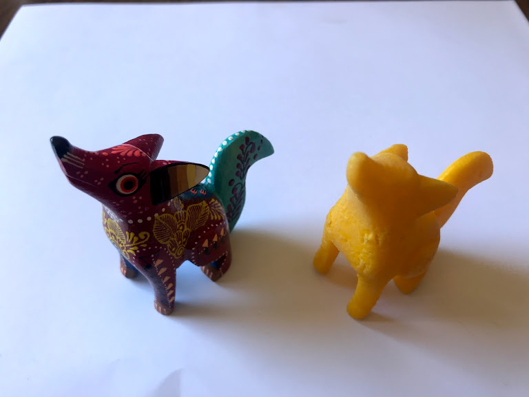
First Attempt
Model without extruding the square.
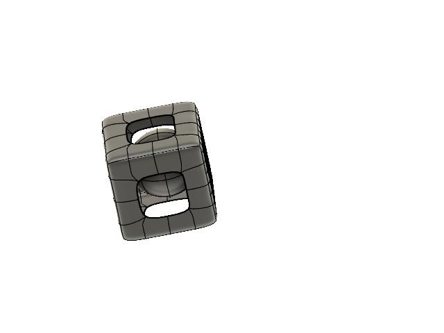
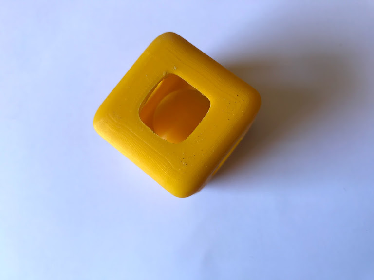
Final Model
Model with square's faces extruded.
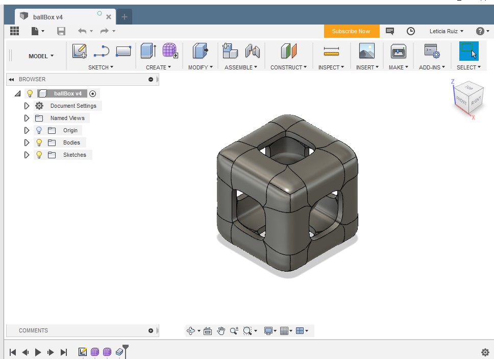
Original model in printer
Model ready to print, it was to big for comfort.
Instructions
- Open Fusion 360
- Go to the sculpting tools
- Create a square and start subdividng each face
- Eliminate excess faces to create a whole in each side
- Create a sphere and insert within the square
- Extrude the square to 5 mm so it will have depth and can be printed (my first attemp was not extruded and couldn't be printed)
- Export to stl for 3D printing
- Open in 3d printer software, set parameteres, fill 25%, minimum support
- Print and wait for final result
- Eliminate support and excess material from piece
- Play with it, it rattles!