The architectures //
>
Von Neumann architecture model>
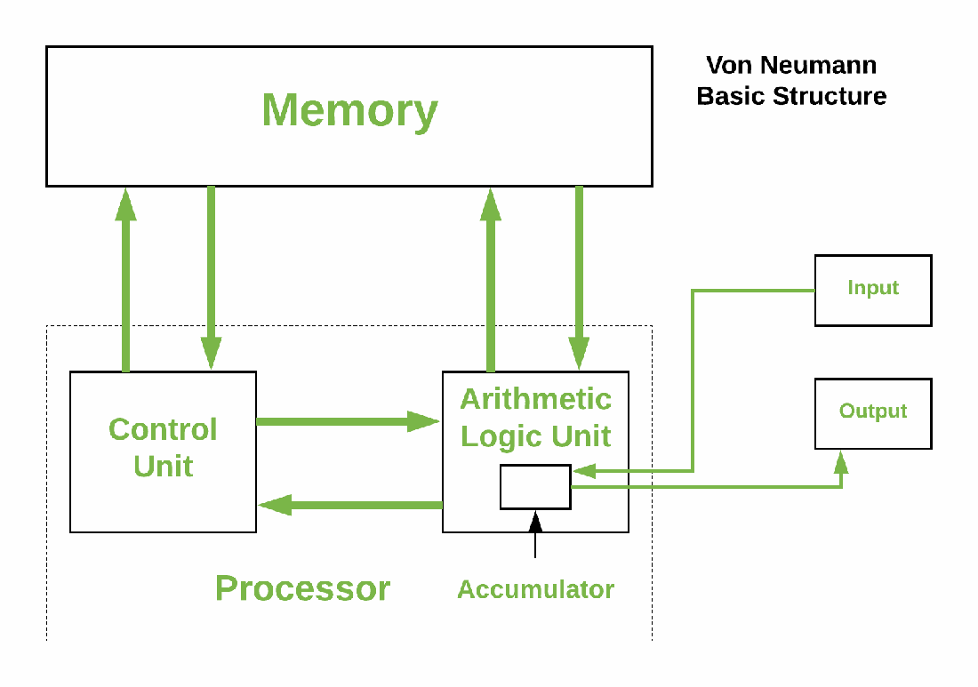
Von Neumann architecture modelThe architecture of John Von Neumann is mainly characterized by processors that have the same storage device for both instructions and data. These, when stored in the same format in memory, uses a single data bus to maintain contact with the CPU. This creates an efficiency in the use of memory, but at the same time requires an ambiguity to be able to recognize and distinguish the data. The computers that use this model are composed by the logical arithmetic unit or "ALU"
This architecture is a family of computer architectures that use the same device to store as for instructions.
Computers with the von Neumann architecture consist of five parts: the Logical Arithmetic Unit (ALU), the control unit, the memory, an input / output device and the data bus that provides a means to transport the data between different parts.
A computer that has this architecture emulates the following procedures:
Nowadays, most computers are built with this architecture because the dynamic design capabilities, such as the implementation and operation of a program instead of two, although it can be slower for certain tasks, is more flexible and allows more concepts such as free programming.
>
Harvard architecture modelUnlike the von Neumann model, the Harvard architecture model, which comes from the Harvard Mark I, is mainly differentiated by the division of the instructions of the data that communicate with the central processing unit in two separate memories. This also generates that different information buses are used. Although a single address bus is common, with a control that can differentiate between both memories. Contrary to John Von Neumann's architecture model, the Harvard model does not require the ambiguity to recognize the data, but it is not as efficient in the use of memory. These computers are always composed of the same elements as those used by the von Neumann model, except that it has two memories, one used for instructions and the other for data, and not a single memory like the other model.
In this model, instructions and data are stored in different caches to improve performance. But for its counterpart, has the disadvantage of having to divide the amount of cache between the two, so it works best only in particular cases when the frequency of reading instructions and data is approximately the same.
In summary, the architecture of Harvard is based on:

A datasheet, data sheet, or spec sheet is a document that summarizes the performance and other technical characteristics of a product, machine, component, material in sufficient detail that allows design engineer to understand the role of the component in the overall system. Typically, a datasheet is created by the manufacturer and begins with an introductory page describing the rest of the document, followed by listings of specific characteristics, with further information on the connectivity of the devices. In cases where there is relevant source code to include, it is usually attached near the end of the document or separated into another file.
Depending on the specific purpose, a datasheet may offer an average value, a typical value, a typical range, engineering tolerances, or a nominal value. The type and source of data are usually stated on the datasheet.
In this case we analyze the data sheet of the Attiny85 microcontroller, which you can find below:
For this practice, use two different IDE's, Arduino and Atmel Studio.
>
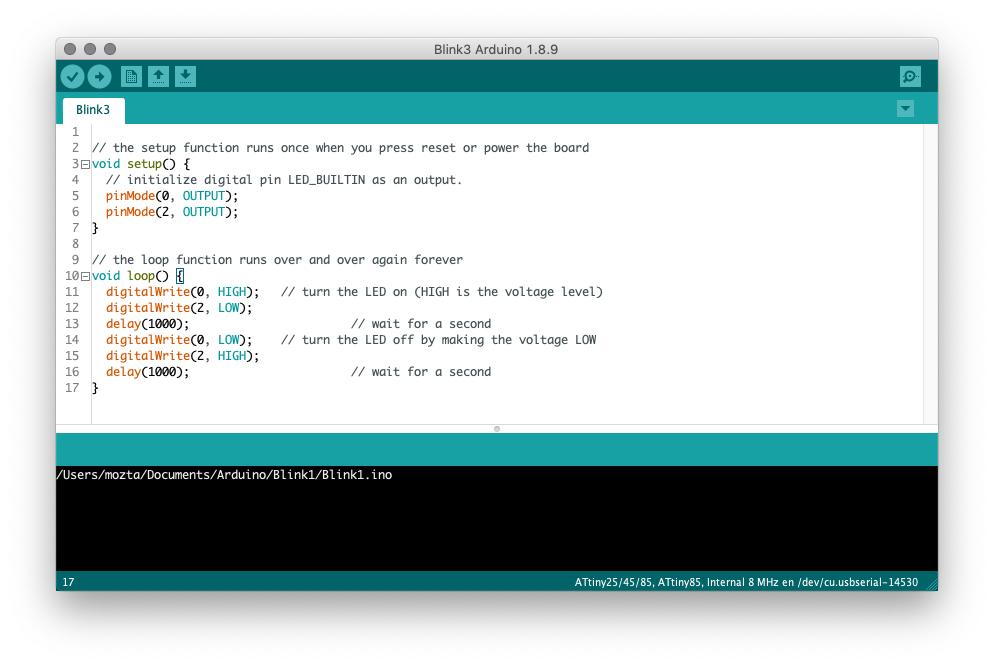
Arduino
The Arduino integrated development environment (IDE) is a cross-platform application (for Windows, macOS, Linux) that is written in the programming language Java. It is used to write and upload programs to Arduino compatible boards, but also, with the help of 3rd party cores, other vendor development boards.
The source code for the IDE is released under the GNU General Public License, version 2. The Arduino IDE supports the languages C and C++ using special rules of code structuring.
>
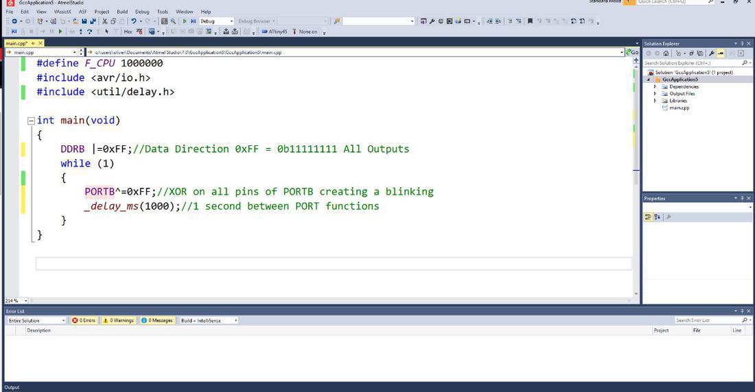
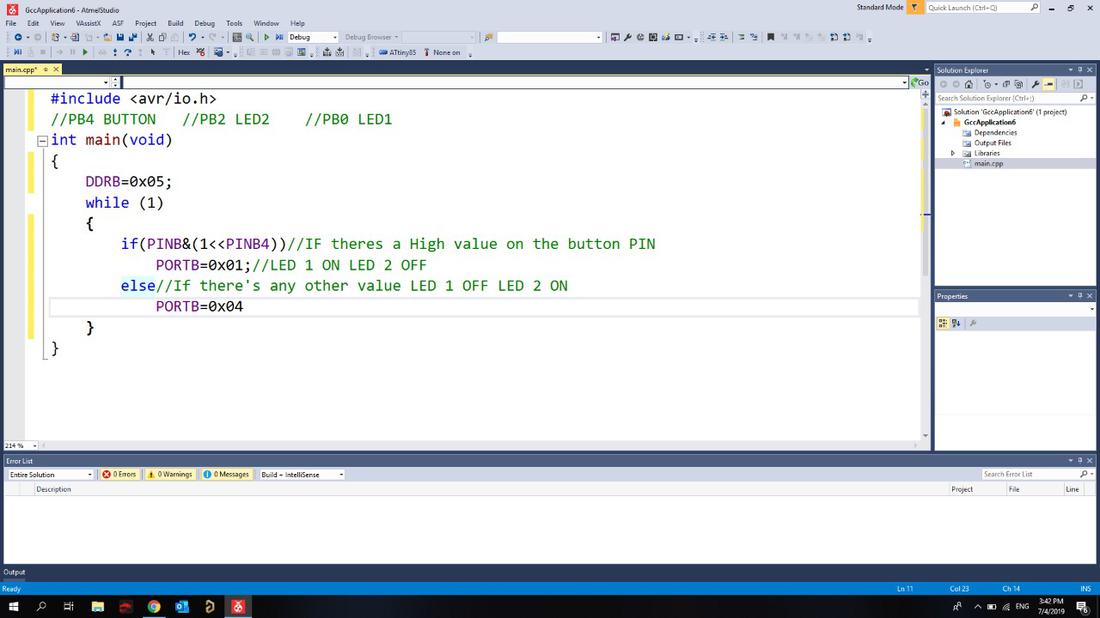
Atmel StudioStudio 7 is the integrated development platform (IDP) for developing and debugging all AVR® and SAM microcontroller applications. The Atmel Studio 7 IDP gives you a seamless and easy-to-use environment to write, build and debug your applications written in C/C++ or assembly code. It also connects seamlessly to the debuggers, programmers and development kits that support AVR® and SAM devices.
Additionally, Studio includes Atmel Gallery, an online app store that allows you to extend your development environment with plug-ins developed by Microchip as well as third-party tool and embedded software vendors. Studio 7 can also seamlessly import your Arduino sketches as C++ projects, providing a simple transition path from Makerspace to Marketplace.

To compare these IDE's I made a small code for each one. The main difference is that with Atmel Studio you can be exact, that is, it gives you the possibility to only alter the necessary bit, since with Arduino it has to be the whole series of bits. In general, with Atmel Studio you have control.
Arduino programming language can be divided in three main parts: functions, values (variables and constants), and structure.
Below I will describe some basic functions to control the Arduino board and performing computations.
Reads the value from a specified digital pin, either HIGH or LOW.
Write a HIGH or a LOW value to a digital pin.
If the pin has been configured as an OUTPUT with pinMode(), its voltage will be set to the corresponding value: 5V (or 3.3V on 3.3V boards) for HIGH, 0V (ground) for LOW.
If the pin is configured as an INPUT, digitalWrite() will enable (HIGH) or disable (LOW) the internal pullup on the input pin. It is recommended to set the pinMode() to INPUT_PULLUP to enable the internal pull-up resistor. See the Digital Pins tutorial for more information.
Configures the specified pin to behave either as an input or an output. See the Digital Pins page for details on the functionality of the pins.
As of Arduino 1.0.1, it is possible to enable the internal pullup resistors with the mode INPUT_PULLUP. Additionally, the INPUT mode explicitly disables the internal pullups.
Reads the value from the specified analog pin. Arduino boards contain a multichannel, 10-bit analog to digital converter. This means that it will map input voltages between 0 and the operating voltage(5V or 3.3V) into integer values between 0 and 1023. On an Arduino UNO, for example, this yields a resolution between readings of: 5 volts / 1024 units or, 0.0049 volts (4.9 mV) per unit. See the table below for the usable pins, operating voltage and maximum resolution for some Arduino boards.
Writes an analog value (PWM wave) to a pin. Can be used to light a LED at varying brightnesses or drive a motor at various speeds. After a call to analogWrite(), the pin will generate a steady rectangular wave of the specified duty cycle until the next call to analogWrite() (or a call to digitalRead() or digitalWrite()) on the same pin.
Below you can find the download links of the original files created for this week.