ASSIGNMENT
Group
- Review the safety data sheets for each of your molding and casting materials, then make and compare test casts with each of them
Individual
- Mill it (rough cut + (at least) three-axis finish cut),and use it to cast parts
TOOLS and SOFTWARE
Solidworks
Roland Milling Machine
This week was intersting for me because I have heard of moulding and casting before but I never fully understood it because I haven't had the chance to go through the process. So, I was really excited to do this week's assigment.
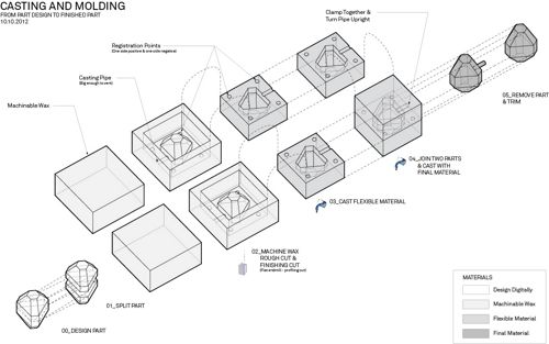
The process is quite easy but it can be a bit tricky to understand. However, after looking at a couple of illustrations, I understood the whole process. I have summarized the process into few step :
- 1- Create the design you want digitally using any modeling software you prefer.
- 2- Mill the design into a wax block to create the first mold.
- 3- Use the mould to create a silicon mould.
- 4- Use the silicon mould to cast your object.
The illustration below can help in understanding the process.
Desiging Using Solidworks
1- I got Iron Man's helmet design file for the helmet from GrabCAD as a solidowrks file. I imported the file to SolidWorks and cut it into half with the help of one of the Fab Engineers at QBIC Fablab.
2- To design the mold, I started by drawing a rectangle parallel to the helmet with dimensions a little bigger than the helmet.
.png)
3- Next, I extruded the rectangle usin the extrude feature and in the extrude options on the left, I changed the "From" to sketch plane.
.png)
4- To make sure the my design is in the middle of the rectangle, I changed the direction of the extrusion from blind to mid-plane and then I set the depth to 71 mm
.png)
5- I drew a square on the surface of the extruded block and extruded it but this time I made the direction of the extrusion 'Blind'. Then, I used the shell feature to make the extruded square hollow from the inside and keep the walls with a thickness of 5mm which was recommended by my collegue. Also, I used the draft feature to make it a bit open at the top and to avoid a 90 deg angle since the milling machine will not be able to mill it properly.
6- Now, since my design is a full head, I will need to create two mold that will be locked together when casting and the molds have to be accurately aligned when locked to make sure the cast is perfect. Therefore, I had to design pins at the corners to help with alignment later on.
To create the pins, I first drew a square around the head as a reference for the location of the pins. Then I drew four circles with diameter of 5mm at the corners of the square.
7- I used the revolve feature and chose the the side of the square (which is passing through the center of the circle) as the axis/centerline for the revolve to be created around it.
.png)
.png)
8- Now, I needed to create two openings at the top of my design. One will be used to pour/inject the casting material through and the other one will help in letting the air out while pouring the casting material. To do that, I first created a plane on the surface of one side of the mould and used the line drawing tools to draw a rectangle and the arc tool to draw a semi-circle as shown in the image below. The rectangle is for the pouring and the semi-circle is for letting the air out.
.png)
9- I extruded the two designs I did and changed the direction of the extrude from the extrude options box on the left to be to the surface of the helmet design.
.png)
10- At this step, the design is almost completed. All is needed is the other half of the mould which is basically the same as this one but mirrored. Hence, I created a plane first to use it as a referrence.
.png)
11- I used the mirror feature to create the second half of the mould and set the plane I created in the previous step as the "Mirror Face/Plane".
.png)
.png)
12- One last step I did was to modify the circular pins for the the aligment that I did in step 6 and change them into slots where the pins can fit into. To do that, I used the cut extrude feature and selected the four pins.
.png)
13- Finally, I exported and saved my design as STL file.
Here's the final design !
.png)
Milling the Mould
Now that I'm done with desiging the mould, it was time to fabricate it. To do that, I used a wax block and milled it using Roland MDX-50 milling machine.
Before milling, I prepared my file using SRP Player which is a CAM software that comes with the machine. This process isn't hard because the software is quiet simple and has all options related to the milling process, quality, tools and other options divided into tabs.
Note: I forgot to take screenshots of this process :(, but I will be adding them soon.
1- I imported my design into the software. First, I started by modifying the size of my model to make sure it will fit within the size of the wax block that was provided by the instructor. I did this through the "Model Size and Orientation" tab.
2- Next, I moved to the "Type of Milling" tab. It is important to edit the options in this tab carefully because it will have an effect on the duration of the milling process. I chose "Faster cutting time" as my type of milling to save time, "Model with many flat planes" and for the last option the type my workpiece as "Block workpiece" and the "Cut top only" because my design will be on the top of the wax block.
3- I went to the "Create Tool Path" tab. I chose the material of my workpiece (Modeling Wax in my case) and input the dimensions of the wax block. I also kept the model placement as "Align Top".
4- Before clicking on the "Create Tool Path" button, I clicked on the edit button next to it to edit the options related to the tools I'm using. This will open a window that has two processes displayed Roughing and Finishing.
5- I selected "Roughing" fisrt and expanded its options. In the options, the bit was set to "Flat" and I needed to change that because the bit I'm using is ball type. To change that I selected that option and some options appeared at the bottom. I changed the option in the dropdown menu "Tool to use for this process" from 2mm sqaure to Milling which automatically changed bit type to ball. Then, I clicked Apply and a warning message appeared and I clicked "Ok"
6- Next, I moved to the Finishing process and expanded its options. I chose 1/16" Ball from the "Tool to use for this process" dropdown menu and clicked Apply.
7- I went back to the main tab and clicked on "Create Tool Path" which will allow the software to calculate and generate the paths for the roughing and finishing and display how much time will the milling process take. The process can previewed using the last two tabs.
8-
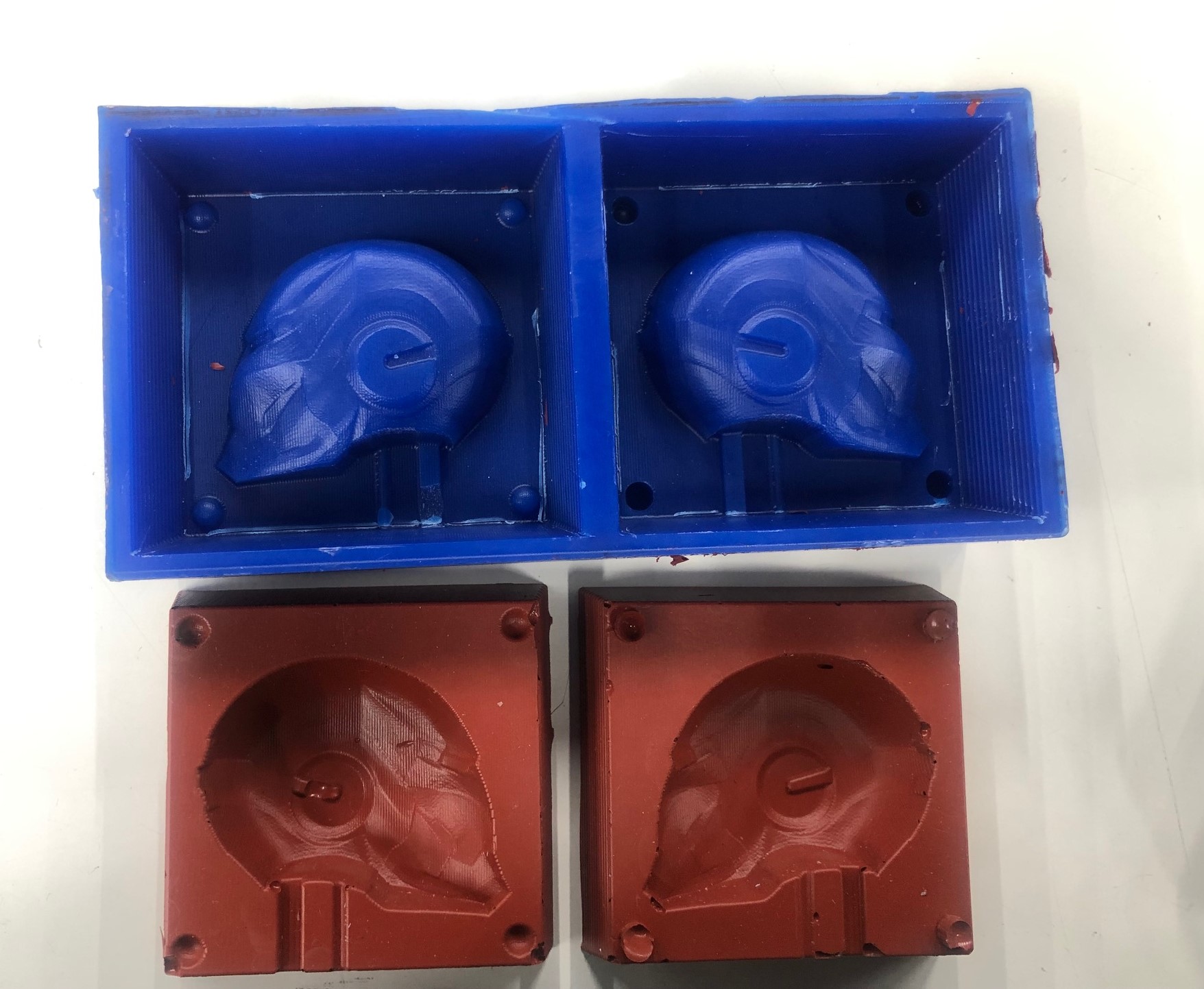
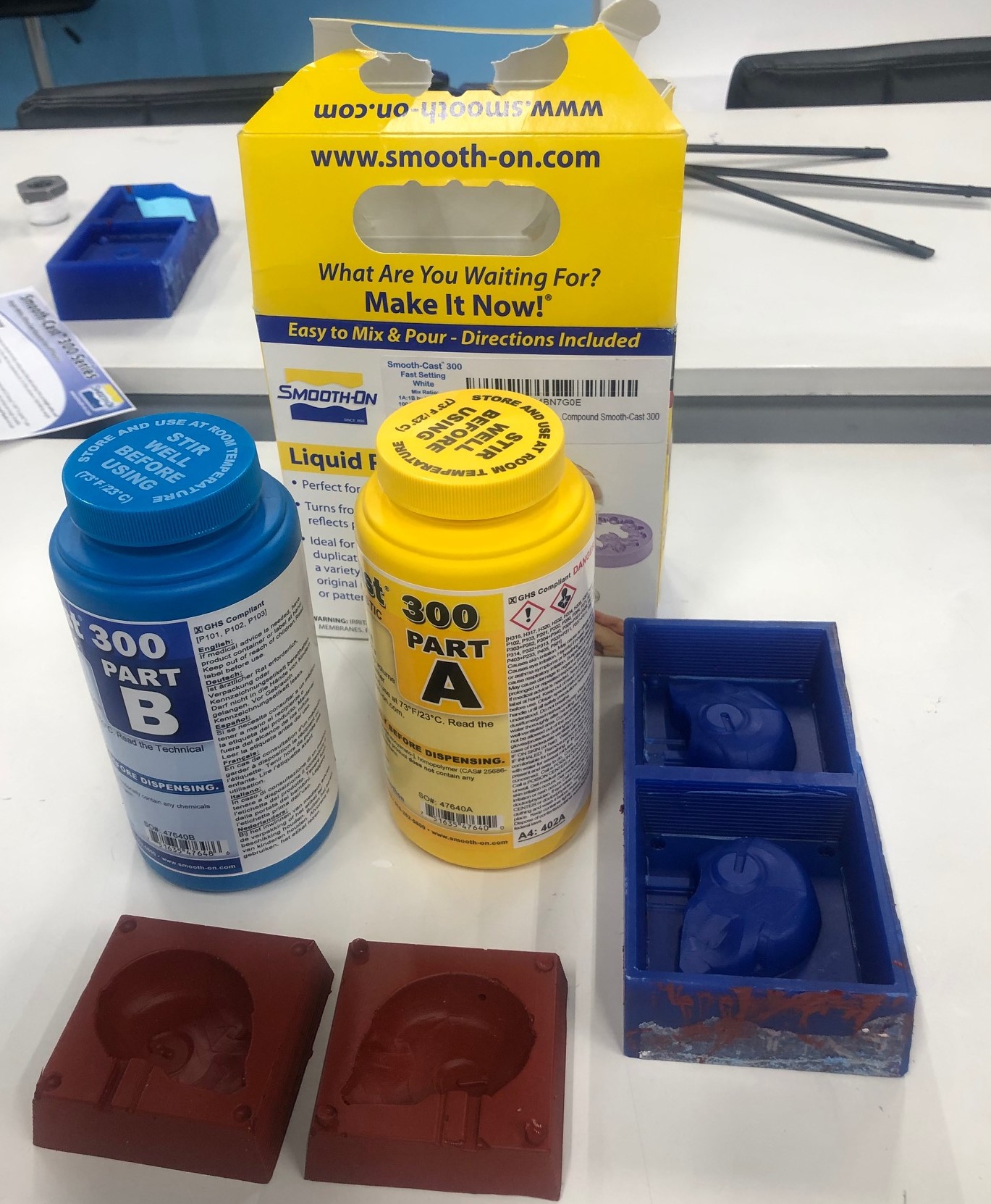
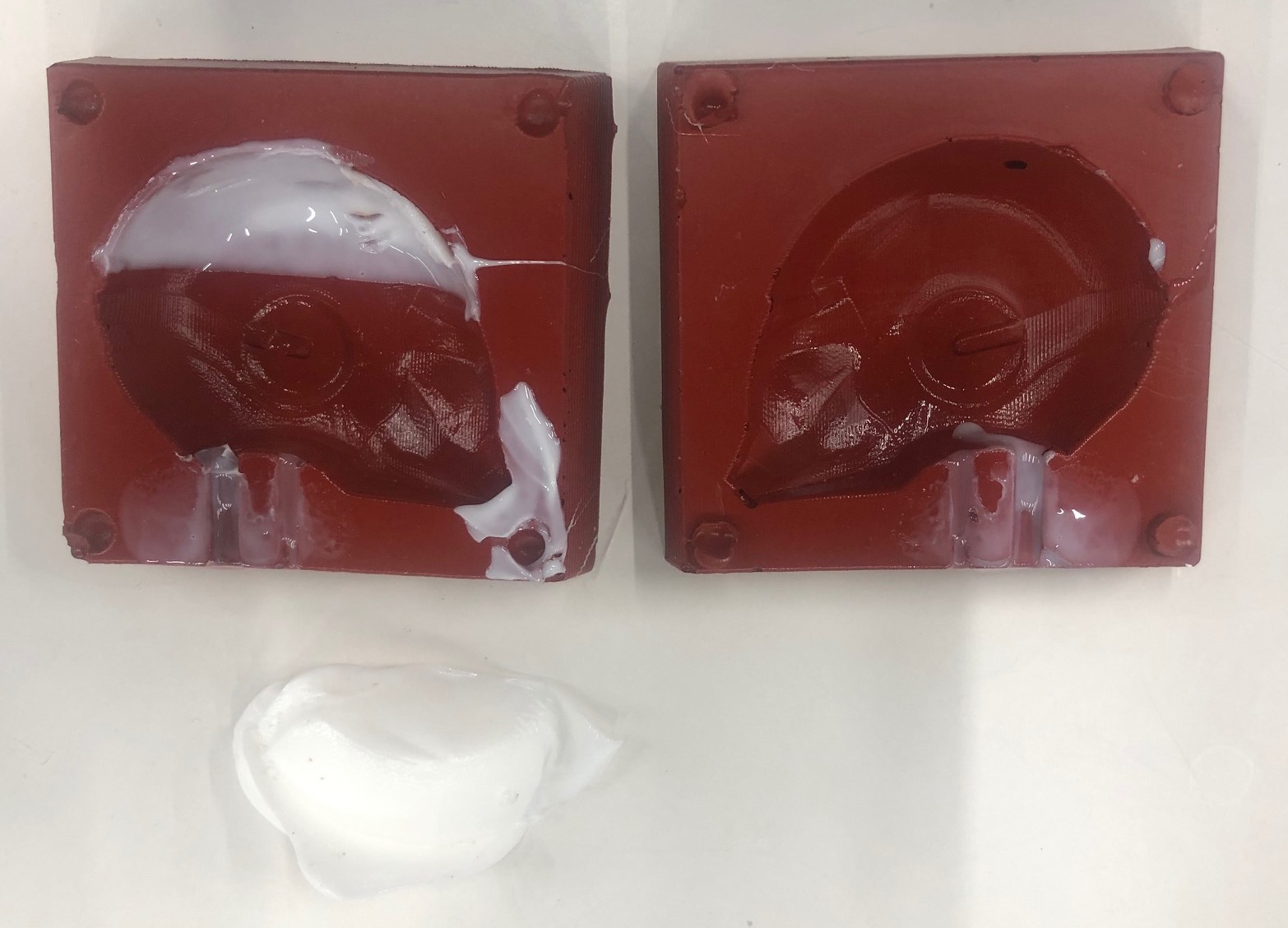
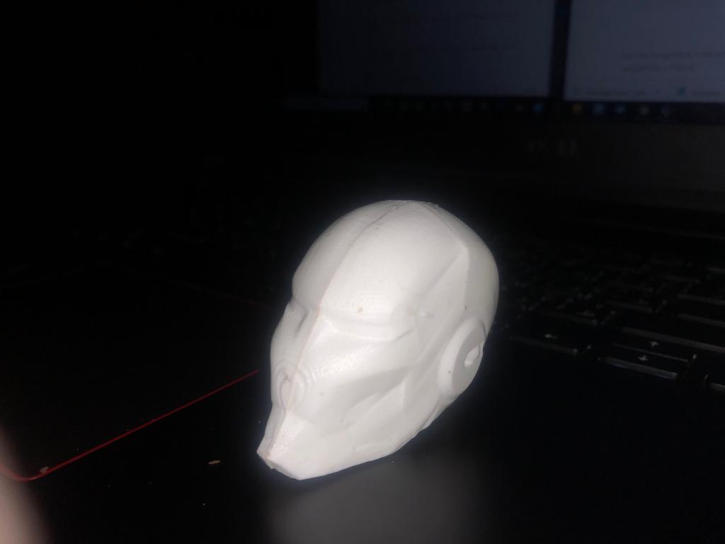
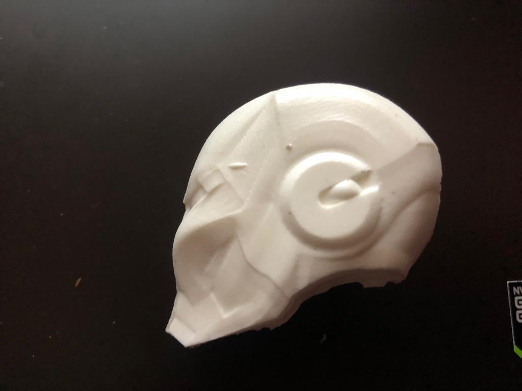
Casting