ASSIGNMENTS
- - model (raster, vector, 2D, 3D, render, animate, simulate, ...) a possible final project
TOOLS and SOFTWARE
Inkscape
FreeCAD
Rhino
For this week, I wanted to get the chance to try designing using different softwares. I'm very good in using Onshape and I know the basics of using Solidworks.Therefore, I decided to stay away from these two this week.
2D Designing Using Inkscape
I started with 2D desiging and wanted to design a simple logo that I can potentially use to represent my final project later. To do that, I used Inkscape which is a free desiging tool/software that can be used to create vector designs or images.
I had no idea how to use inkscape so I watched tutorials on Youtube to be able to use the basic features and I also like learning a software by just exploring the diiferent tools and features while I design.
1- I started by creating a new image and set its dimensions. I wanted to design something that refers to smart and farming/plating at the same time so I started looking for inspirations on the internet and I decided the simplest two things to use are a light bulb to represent "smart" and leaves to represent "plants" and combine them in way.
.png)
2- Now, instead of drawing the lighbulb and leaf images from scratch, I looked for a transparent black and white drawing of both elements and imported those into the software.
.png)
3- The image of the leaf I liked was not completely transparent and it was in pixles and I wanted to be able to edit it so I used the trace tool in inkscape which helps converting a bitmap/raster to a vector. I got the trace tool by going to Path > Trace Bitmap. I tried the different settings in the trace tool dialog box until I was satisfied with the output and saved the trace.
.png)
4- I imported the trace of the leaf that I saved and dragged it in the middle of lightbulb drawing.
.png)
5- I made another copy of the leaf trace and flipped it and made a bit smaller so it looks nicer this way. Then, I tried to trace the lightbulb image again because I wanted it to be an outline only with no color inside and the result was okay.
.png)
6- Finally I used the different coloring tools to change the color of the logo.
Here's the final result !
.png)
2D Designing Using GIMP
Since this assigment is all about genrally trying the different platforms/softwares available to model, I wanted to try another software so I went for GIMP which is a free image editor that can be used for image editing, garphic designing, creating artwork and many more.and designed a very simple random logo just to be able to test the different features.
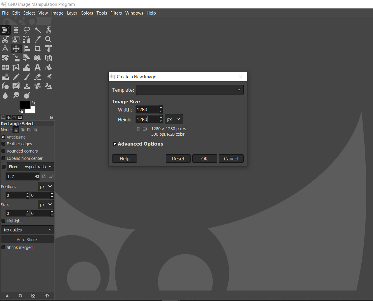
1- I started by creating a new image through File > New which will open up the "Create a new image" dialogue box and then I set the dimension to 1280x1280 pixles.
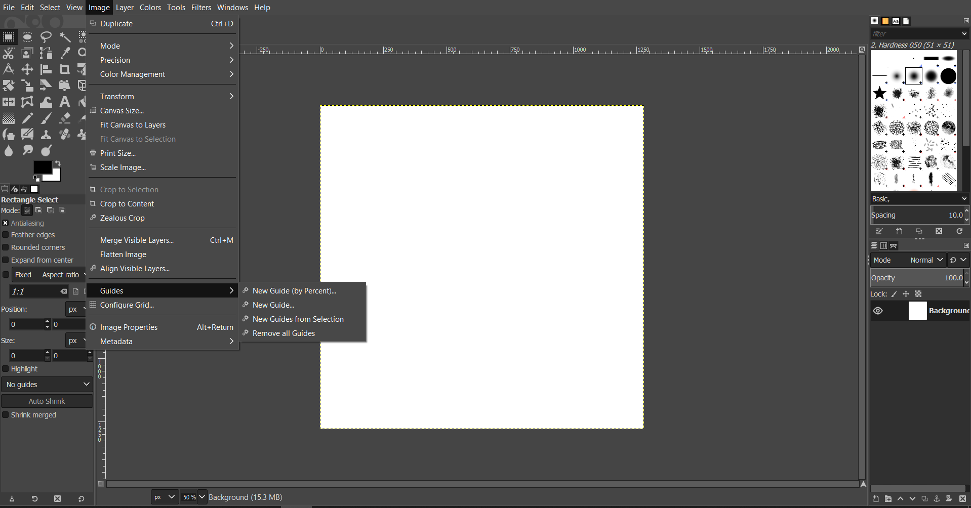
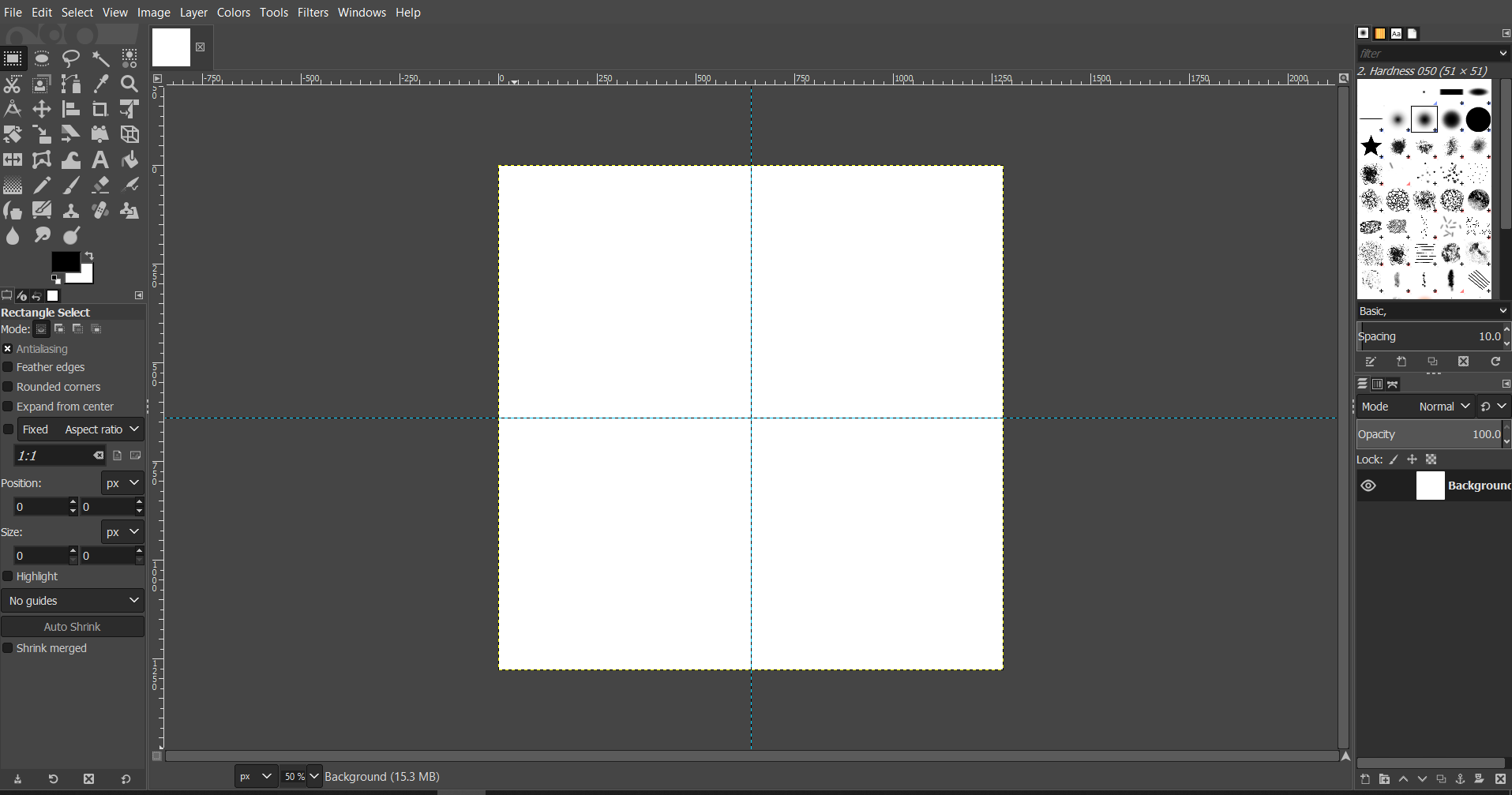
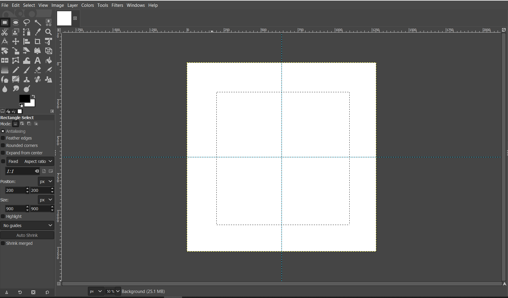
2- I added vertical and horizontal guides that are placed in the center of the canvas to help me while drawing my design. I did this by going to Image > Guides >New Guide(by Percent) and entered 50% to make sure the guides are in the center.
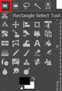
3- I created a square by using the "Rectangle Select Tool" from the toolbox on the left. I dragged the tool while pressing the Shift key on the keyboard to draw a square. Then, I changed its dimensions to 900 from the size box on the bottom left.
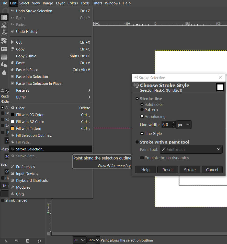
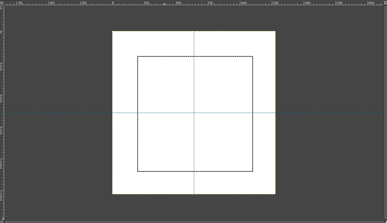
4- Now, to turn the selection into an actual shape, I went to Edit > Stroke Selection. Which will open the "Stroke Selection" dialoge box where I can specify the width of the line and other options. After I was done, I clicked on "stroke" which turned my selection into an actual square.
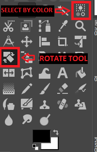
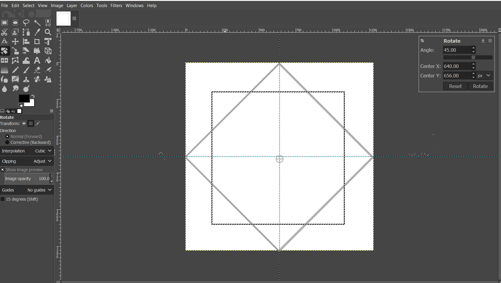
5- I rotated the square so that it looks like a diamond. I did this by using the "Select color tool" from the toolbox on the left to select the square shape. Then, I selected the "Rotate Tool" which opens up a dialouge box on the top right where I entered 45 degrees as my rotation angle.
6- I then created another square that intersects with the the rotated square using the same steps I followed previously.
7- Now, I wanted to add some colors to the simple "design" I did. Therefore, I selected the rotated square first and then used the toolbar on the right side to select the type of fill I want to use for the square. I decided to go with patters so I selected the "Patterns" tab form the top.
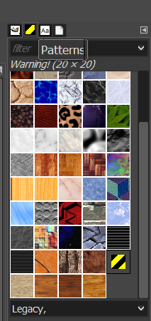
Finally, I selected a pattern and then used by going to Edit > Fill with Pattern" and I did the same thing with the outline of the other square.
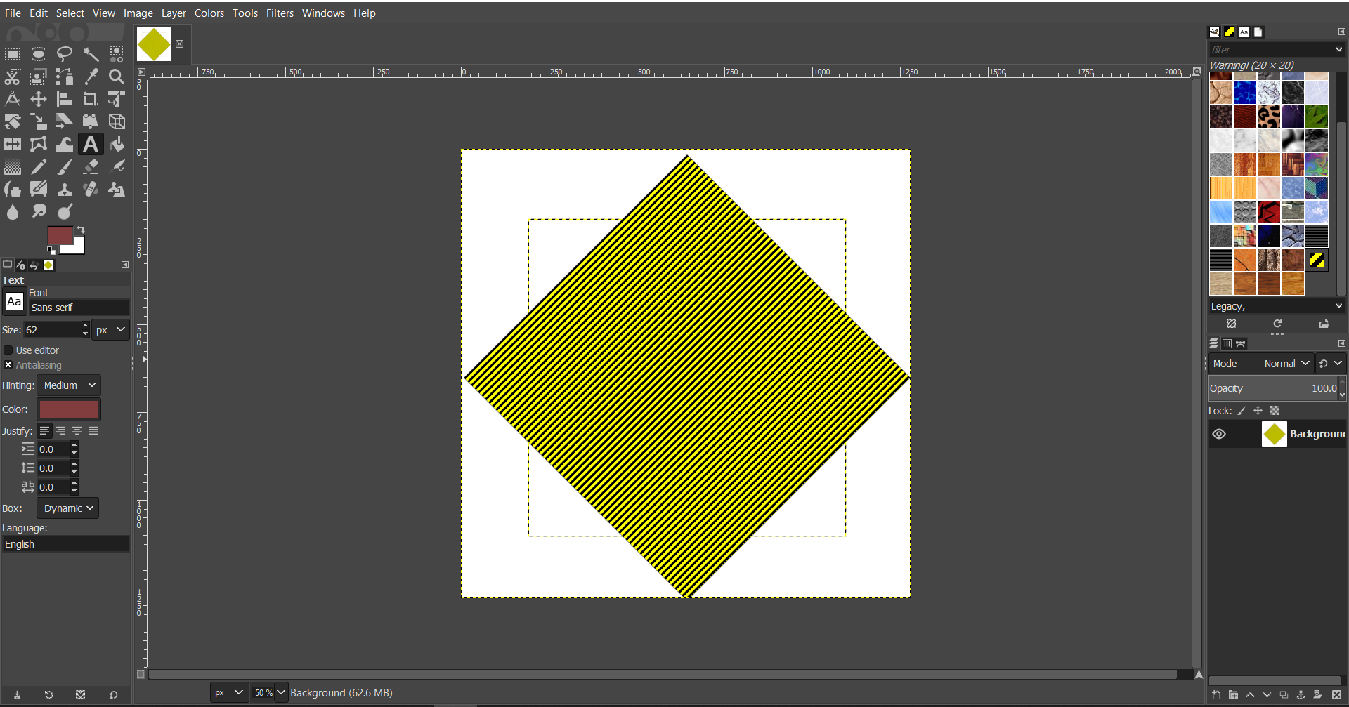
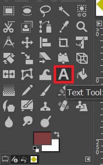
9- I added text (my name) in the middle of the rotated square by selecting the text tool from the toolbox on the left.
I chose the font I desired and specified the size of the text using the text options below the toolbox on the left.
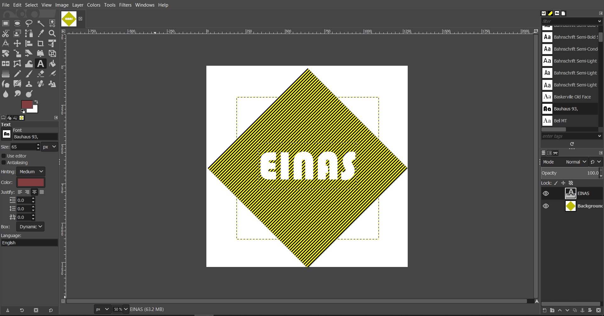
10- Finally, I exported the design as an image by going to File > Export.
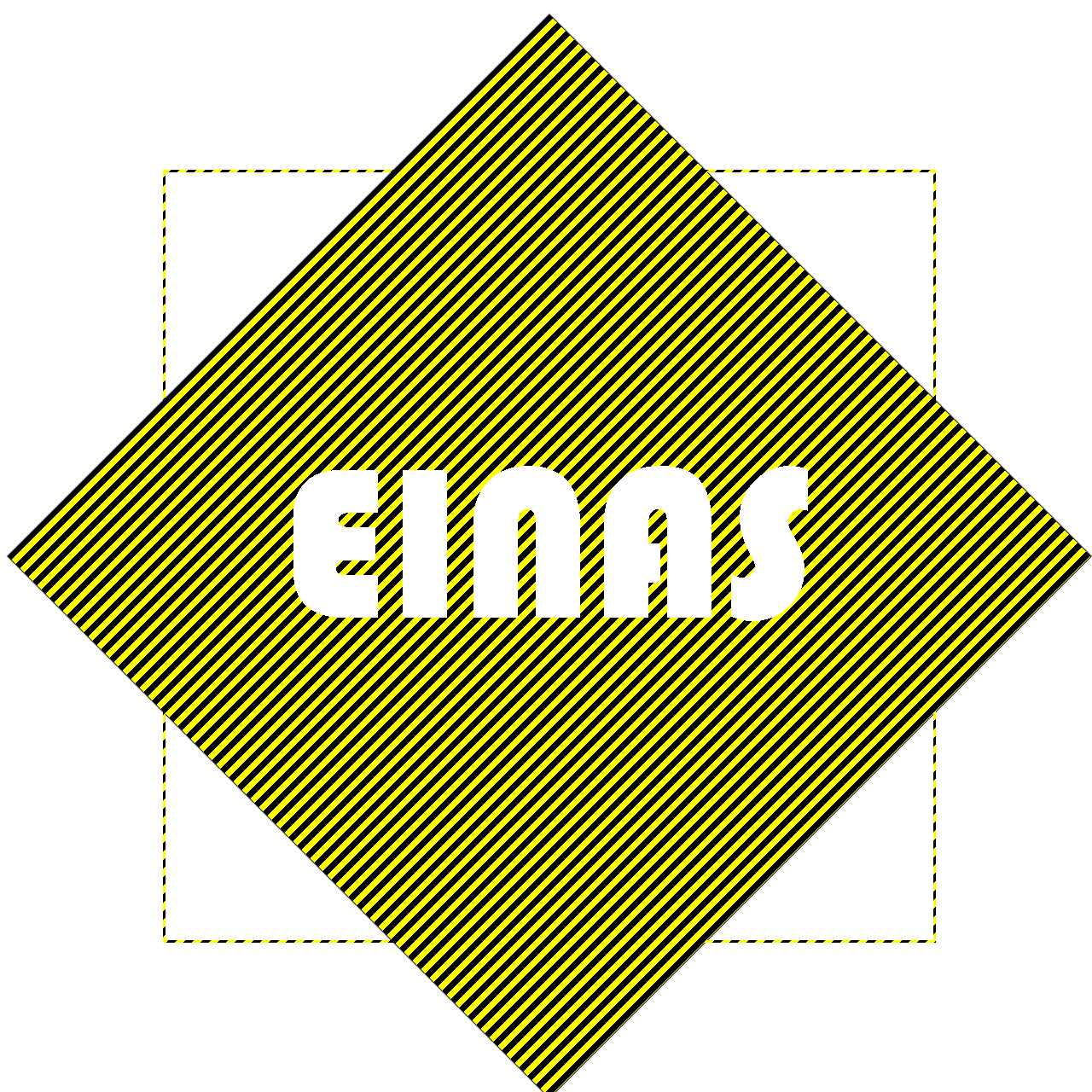
Here's the final design
3D Designing Using FreeCAD
In 3D desiging, Dr.Neil discussed different types during the class and he emphasized on the importance of learning how to do a parametric desig. Therefore, I started reading more about parametric design and a collegue recommended FreeCAD for parametric modelling.
I started watching tutorials to understand how to do parametric design and found a very helpful and detailed tutorial on youtube. So, here are the steps I followed to do this type of 3D desiging.
1- I started by creating a new file. Then, using the drop down menue from the top toolbar, I chose part design which will show new features on the toolbar.
.png)
2- From the top toolbar I clicked on Create a new part and make it active > Create a new body and make it active.
.png)
3- I clicked on the body icon from the left toolbar. Then from the top toolbar, I clicked Create a new sketch > Chose XY as my base plane.
.png)
4- From the dropdown menu on the top toolbar, I changed from part design to spreadsheet and then clicked on 'Create a new spreadsheet'. Then in the spreadsheet, I entered the parameters (Shown in the picture below" of the press-fit square I'm planning to design.
For each parameter I right-clicked on the parameter cell and opened properties and added an alias and the unit of the value.
.png)
5- I moved back to the sketch window and started drawing my square and for each entity, I added a constraint. Instead of entering a number in the value cell, I write an equation using the parameters I previously defined in the spreadsheet which would relate the parameters together
.png)
.png)
.png)
An example would be the width of the slot for joint which depends on the thickness of the material used. Hence, during sketching, I will enter an equation relating it to the thickness and kerf of the machine instead of the value and the software will calculate it based on these values.
.png)
6- I completed the whole sketch the same way until its finished.
.png)
The images below show how the square dimensions changed when I changed the thickness of the material used.
.png)
.png)
.png)
.png)
3D Designing Using Rhino
I decided to try Rhino for the 3D design. Therefore, I designed a planting pot that may be potentially used for my final project.
1- I changed my view to top plane only so its easier for me to focus since I'm not used to seeing the multiple views at the same time.
.png)
.png)
2- I started by drawing a circle using the circle tool from the toolbox on the left and entered 50mm as the radius in the command box on the top.
.png)
3- I created another circle by using the offset feature by typing it in the command window on the top and then specified the value of the offset to 20mm.
.png)
4- I changed my view back to the multiple views screen and I started working in the "Prespective" view because I wanted to move the bigger circle up.
.png)
5- I moved the bigger circle by simply selecting the circle and using th movemoent arrow that is pointing up to move the circle up. This way the small circle represents the bottom of the planting pot and the bigger one represent the top.
.png)
6- I changed my view to prespective only because this is the only view I need for now.
7- Now, I wanted to create the body of the pot so I decided to use the loft tool by typing it into the command window on the top. This tool (In my own humble words) creates a surface between selected planes.
.png)
8- Next, I clicked on the prespective to see the different view I can see my design in and I tried them all and chose the "Ghosted" so that I can see my design filled instead of just lines.
.png)
9- The shape I created is open from both top and bottom and to be able to create an actual planting pot, the bottom needs to be closed. Therefore, I clicked on "Boolean Operations" from the toolbox on the left then I chose the feature "Cap planar holes" which covered both the top and the bottom of the pot shape.
.png)
10- As I mentioned previously, I only needed to cover the bottom of the pot. So, I used another feature called "Extract Surfaces" and removed the top cover of the pot.
.png)
And that's it. Here's the final design.
.png)
.png)
My Feedback
In the end, I want to share my final thoughts regarding the softwares I used during this assignment.
For 2D desiging, Inkscape was a pretty good software, its user-friendly and easy to navigate, and it has so many features that are quite easy to use. On the other hand, GIMP is considered a powerful software and I don't I'll be able to give a full detailed feedback about it since I have used to design something extremely simple and didn't use a lot of the tools available. However, one thing I noticed about GIMP is that it might be challenging for beginners like me because I couldnt find the tools easily but I strongly believe that its going to be easy for users who are used to designing and editing images or users who are familiar with Photoshop.
For 3D designing, I know my way around Solidworks which is extremely powerful but quite expensive. I also usually use Onshape which is cloud-based and I consider it a version of Solidworks that is suitable for students and beginners. As for the ones I used in this assignment (FreeCAD & Rhino), I enjoyed using both of them and learned alot. FreeCAD is easy for beginners ad really useful especially when it comes to parametric design. I was surprised when I used Rihno because I always had the idea that its a bit hard but it was even easier the FreeCAD and all the tools where clear.